Transcription
NEC Code Calculations for SolarInstallationsfor Inspectors and Building Officials
About Cari Williamette Cari Williamette works with EcoVision Electric inMinneapolis, MN performing 3rd party testingand installation of solar PV systems. She is alicensed master electrician, and an ICC certifiedelectrical inspector and building official. Whennot in the field, she teaches classes in codecalculations, code update, and Article 690 (solarPV).
Solar Photovoltaic What is it? How does it work? Basic terms
Solar Photovoltaic System (PV) The total components and subsystems that, incombination, convert solar energy into electric energysuitable for connection to a utilization load. (NEC690.2)
Solar Cell The basic photovoltaic device that generateselectricity when exposed to light. (NEC 690.2)
Solar Cell
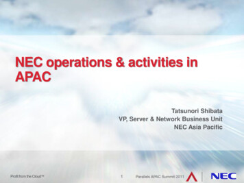
PV Cell ComparisonThere are four main different types of solar PV cells. The tablebelow gives an indication of how they compare to each other.*HybridPV combines monocrystalline and thin-film silicon to produce cells with the bestfeatures of both technologies**Standard Test Conditions (STC) are: 25 C, light intensity of 1000W/m2, air mass 1.5
Module A complete, environmentally protected unitconsisting of solar cells, optics, and othercomponents, exclusive of tracker, designed togenerate dc power when exposed to sunlight.(NEC 690.2)
Module 240 Watt
AC Module A complete, environmentallyprotected unit consisting ofsolar cells, optics, inverter,and other components,exclusive of tracker,designed to generate acpower when exposed tosunlight. (NEC 690.2)
AC Module Addition of a micro-inverter on site DOES NOTqualify as an AC module.
Array A mechanically integrated assembly of modules orpanels with a support structure and foundation,tracker, and other components, as required, to form adirect-current power-producing unit. (NEC 690.2)
Building Integrated Photovoltaics Photovoltaic cells, devices, modules, or modularmaterials that are integrated into the outer surfaceor structure of a building and serve as the outerprotective surface of that building. (NEC 690.2)
Photovoltaic Modules/Shingles A roof covering composed of flat-platephotovoltaic modules fabricated in sheetsthat resemble three-tab compositeshingles. (2012 IBC, 202)
Balance of System (BOS) All of the system components except thePV modules. (Sandia Labs)
DC Combiner A device used in the PVSource and PV Outputcircuits to combine two ormore dc circuit inputs andprovide one dc circuitoutput. (NEC 690.2,proposed 2014)
PV Wire or USE-2 Also called RHH or RHW wire, AWC cross-linkinsulation, type XLPE, can be used in aerial, racewayor direct burial allocations. Conductor is copper.
DC Disconnect Note wiring requirementsfor increased arcingcapability of DC circuits
AC/DC sine waves
Inverter Equipment that isused to changevoltage level orwaveform, or both,of electrical energy.(NEC 690.2)
AC Disconnect
Meters Production Meter Bi-directionalUtility Meter
Weather Stations Wind and temperature Pyranometer or Irradiance Sensor
Monitoring
Hybrid System A system comprised of multiple power sources.(NEC 690.2)
Stand-Alone System A solar PV system that supplies powerindependently of an electrical production anddistribution network. (NEC 690.2)
Interactive System A solar PV systemthat operates inparallel with, andmay deliver power to,an electricalproduction anddistribution network.(NEC 690.2)
Multimode inverter (system) Equipment having capabilities of both the utilityinteractive inverter and the stand-alone inverter(NEC 690.2 proposed 2014)
Monopole Subarray A PV subarray that has two conductors in theoutput circuit, one positive ( ) and onenegative (-). (NEC 690.2)
Bipolar Photovoltaic Array A PV array that has two outputs, each havingopposite polarity to a common referencepoint. (NEC 690.2)
Trackers – Not defined in Code Single Axis Dual Axis
Ground Mount Systems
Roof Mount Systems
Pole or Canopy Mount Systems
Others
Codes NEC NESC IBC IRC IFC
NEC (National Electrical Code) 2011 Edition unless otherwise noted
Art. 705 Interconnected ElectricPower Production Sources Covers installation of one or moreelectric power production sourcesoperating in parallel with a primarysource of electricity.
Art. 690.4(A)Installation PV Systems A PV system shall bepermitted to supply abuilding in addition toany other electricitysupply systems.
Art. 690.4(B)Identification & Grouping PV circuits shall not be contained in thesame raceway as conductors of non-PVsystems unless separated by a partition. PV conductors shall be identified andgrouped as required in (B)(1) – (4)
Art. 690.4(B)(1) – (4)(new) (1) PV source circuits (2) PV output & inverter circuits (3) Multiple systems (4) Grouping
Art. 690.4(C)Module Connection Removal of amodule shallnot interrupta groundedconductor
Art. 690.4(D) Equipment Identified and listed for the application
Art. 690.4(E)Wiring & Connections (new) Shall be installed only by qualified persons See Art. 100 for definition NABCEP certification? (North American Boardof Certified Energy Practitioners)
Art. 690.4(F)Circuit Routing (new) PV source & output conductors In or out of conduit Inside of a building Routed along structural members Where imbedded in roofing (or concealedby roofing material), location shall beclearly marked
Art. 690.4(G)Bipolar PV Systems (new) Disconnecting means and OCPD for eachmonopole shall be in separate enclosures,unless listed for bipolar.
Art. 690.4(H)Multiple Inverters (new) Directory required(705.10) showinglocation of all ACand DCdisconnectingmeans, unlessgrouped together
Art. 690.31(B)Single-conductor Cable USE-2 PV wire In raceway onlywhen 30 voltsand readilyaccessible,690.31(A)
Art. 690.31(E)DC circuits inside a building DC PV source or output circuits where run inside abuilding, shall be contained in metal raceways or MCcable.
Art. 690.31(E)(1-4)DC Inside Buildings Beneath roofs requiresmin. 10 inch clearance FMC 1” requires guardstrips, follow buildingsurface, or be protectedfrom damage Raceways, enclosures,conduit bodies shall bemarked. (ANSI Z 535.4)
Art. 690.33(E)Connectors Connectors shall be rated for interrupting current OR Require the use of a tool to open and be marked.
Art. 690.35Ungrounded PV Systems Ground fault detection system required Warning label Listed for purpose
Art. 690.7Maximum Voltage Sum of Voc (Open Circuit Voltage) of modulesin series Multiply by correction factor in Table 690.7 Or use manufacturer’s correction factors St. Paul average mean low temperature isapproximately 4 deg. F 1.18 (-16 deg. C)
Using 13 modules per string(in series)Using Table 690.736.9 volts X 1.18 43.54 volts43.54 X 13 566.02 voltsUsing Manufacturer’s Info25 – (-16) 41 deg. C41 X .36% 14.76 %(increase by 14.76%)36.9 volts X 1.1476 42.35 voltsNote Max. System Voltage42.35 X 13 550.55 voltsNEC prefers to use manufacturer’s info when possibleSee 690.7(A), second paragraph
Watch DC voltagerange on inverter Inverter only putsout at voltage onnameplate –matching utility
Art. 690.7(C)Voltage limitations In one and two family dwellings, PV source andoutput circuits (DC) are permitted to have a max.voltage up to 600 volts (1000 Vdc for 2014) Over 600 volts shall comply with Part IX and Art. 490
Art. 690.8(A)Circuit Sizing & Current Edge-of-Cloud Effect
Art. 690.8(A)Maximum Current (1) PV Source Circuit Currents (2) PV Output Circuit Currents Isc (derated) X 125% foredge-of-cloud effectUsing Manufacturer’s Info33 C (avg. high MN) - 25 8 C8 X .053% 0.424 %(increase by 0.424 %)8.45 X 1.00424 8.49 A8.49 X 1.25 10.61 Amps
Art. 690.8(A)Maximum Current (3) Inverter Output Currents Inverter Rating (AC)NoEdge-of-Cloudeffect13 Amps
Art. 690.8(B)(1)OCPD (revised) PV system currents considered continuous Max. current from (A) X 125% Permitted to “round up” from 240.4(B), (C), (D)DC circuitsFrom 690.8(A)(1)8.45 X 1.25 10.61 AmpsFrom 690.8(B)(1)10.61 X 1.25 13.26 Amps15 Amp fuseAC circuitsFrom 690.8(A)(3)13 AmpsFrom 690.8(B)(1)13 X 1.25 16.25 Amps20 Amp fuse
Art. 690.8(B)(2)Conductor Amp. (revised) Sized to carry the larger of (a) or (b) and (c) (a) Max current from (A) X 125% for continuous (b) Max current from (A) after conditions of usehave been applied (c) Conductor selected must be protected by OCPDafter conditions of use have been applied
DC conductor sizing690.8(B)(2)(a)From 690.8(A)(1) 8.45 X 1.25 10.56 AmpsFrom 690.8(B)(1) 10.61 X 1.25 13.26 Amps690.8(B)(2)(b)Table 310.15(B)(3)Conduit 3” off roof, add 40 FTable 310.15(B)(2)(a) 90 40 130 F .76 correctionTable 310.15(B)(3)(a) 8 conductors in conduit 70%10.56/(.76 X .7) 19.84 Amps690.8(B)(2) Use larger number 19.84 Amps#12 Cu [verify fuse sizing 690.8(B)(2)(c)]
AC conductor sizingFrom 690.8(A)(3)From 690.8(B)(1)690.8(B)(2)(a)13 Amps13 X 1.25 16.25 Amps690.8(B)(2)(b)Table 310.15(B)(3)Conduit 3” off roof, add 40 FTable 310.15(B)(2)(a) 90 40 130 F .76 correctionTable 310.15(B)(3)(a) 8 conductors in conduit 70%13/(.76 X .7) 24.44 Amps690.8(B)(2) Use larger number 24.44 Amps#12 Cu [verify fuse sizing 690.(B)(2)(c)]
Art. 690.9Overcurrent Protection (A) Circuits and EquipmentArt. 240 PV source circuitPV output circuitInverter output circuitStorage battery conductorsEquipment
Art. 690.9(A)Circuits & Equipment Exceptions: No external sourcesOR Short-circuit currents from all sources do notexceed the ampacity of the conductors
Available Fault Currents Available fault currents in DC system limitedto Isc, limited supply system For ballpark sizing, industry rule of thumb is 2X Isc. Possibility of 6 X I(max) on AC side of inverter,depending on characteristics, for 3 sine wavesor fewer Currently being researched
Short Circuit Test Results - NREL
Art. 690.9(C)PV Source Circuits Accessible, not Readily Accessible
Art. 690.9(D) Direct-Current Rating OCPD shall be listed for usein dc circuits and have theappropriate voltage,current, and interruptratings 600 Vdc, 1000 Vdc,1200Vdc, 1500 Vdc
UL 2579 PV Standard for fuses
UL 2579 PV Standard for fuses Ability to mitigate low magnitude faults Performance in extreme temps Proven in solar environments
Art. 690.9(E)Series Overcurrent Protection In PV source circuits, a single overcurrentprotection device shall be permitted to protect thePV modules and the interconnecting conductors.
Art. 690.10(E)Back-fed Breakers (new) Plug-in type back-fed breakers connected to astand-alone inverter output shall be secured,408.36(D)
Backfed Breaker w/retainer clip
Art. 690.13Disconnecting Means Means shall be provided todisconnect all current-carrying dcconductors of a PV system from allother conductors in a building A switch shall not disconnect thegrounded conductor (exceptions)
Art. 690.13Exceptions (revised) Part of ground-fault detection system Part of an arc-fault detection system- or- or Only for PV array maintenance Accessible only by qualified persons Rated for max. dc voltage and current- and- and
Art. 690.14 Additional Provisions (A) not required to beSUSE rated (C)(1) readily accessible (2) Permanently marked(3) Suitable for use – location(4) Maximum of 6(5) Grouped (not requiredat array) Art. 690 does not specifyline-load orientation
Art. 690.14(D)Disconnecting Means (D) Utility-Interactive Inverters inNot-Readily-Accessible locations Permitted to be mounted in areas that are notreadily accessible (1) DC disconnect within site of inverter (2) AC disconnect within site of inverter (3) Additional AC disconnecting means in readilyaccessible location, 690.14(C)(1) (4) Plaque shall be installed, 705.10
AC disconnectDC disconnect
Art. 705.10
Art. 690.15Disconnect of PV Equipment Means shall be provided to disconnectequipment InvertersBatteriesCharge controllersEtc. If energized from more than 1 source, alldisconnects shall be grouped and identified
Art. 690.16 Fuses(new & revised) (A) Disconnecting means shall be provided todisconnect a fuse from all sources of supply if thefuse is energized from both directions (B) Fuse Servicing Disconnecting means shall be installed on PV outputcircuits where fuses must be serviced that cannot beisolated from energized circuits Shall be within sight of, and accessible to, the locationof the fuse If more than 6 ft away, directory is required Non-load-break-rated shall be marked
Art. 690.17Switch or Breaker Disconnecting means shall consist of a manuallyoperable switch(es) or circuit breaker(s) Readily accessibleExternally operablePlainly indicatingInterrupting rating sufficient for nominal voltage andcurrent Where all terminals may be energized in the openposition, a warning sign shall be required
Art. 705.12Point of Connection (A) Supply Side Power production source is permitted to beconnected to the supply side of the servicedisconnecting means Sum of the ratings of all overcurrent devicesconnected to power production sources shallnot exceed the rating of the service (new)
Art. 705.12Point of Connection (D) Utility-Interactive Inverters Permitted to be connected to the load side of the servicedisconnecting means (1) Dedicated OCPD and disconnect (2) The sum of the amp ratings of OCPD in circuitssupplying power to a busbar shall not exceed 120% ofbusbar/conductor rating (3) Shall be on the line side of all ground-fault protection (4) Equipment shall be marked (5) Suitable for backfeed (no line-load marking) (6) Utility-interactive backfeed can omit tie-down
Art. 705.12Point of Connection (D)(2) The sum of the ampratings of OCPD in circuitssupplying power to a busbarshall not exceed 120% ofbusbar/conductor rating
Art. 705.12Point of Connection 8 X 30 Amp OCPD’s 240 Amps225 Amp main 240 465 Amps400 Amp bussbar X 120% 480 AmpsPanel is acceptable
Art. 705.12(D)(7)Inverter Output Connection Unless the panelboard is rated not lessthan the sum of the ampere ratings of allovercurrent devices supplying it, aconnection in a panelboard shall bepositioned at the opposite (load) end fromthe input feeder location or main circuitlocation. A permanent warning label shall beapplied
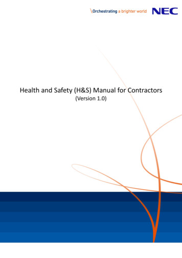
3121The markings shall be of sufficientdurability to withstand theenvironment involved. NEC 110.2154NEC2011765Materials used for marking shall bereflective, weather resistant andsuitable for the environment.IFC 605.11.1.1.123Net MeterAC Disconnect / Breaker / Pointsof ConnectionPer NEC 690.14(C)(2) & 690.156InverterBuilding/StructurePer NEC 690.547DC Disconnect/BreakerPer NEC 690.5(C)1Per NEC 690.56(B)MAIN SERVICE DISCONNECTAt the location of the ground-fault protection, normally at theinverter, warning of a shock hazard (NEC 690.5[C]).4Per NEC 690.17 (4)Main ServiceDisconnect4Per NEC 690.52Breaker Panel/Pull BoxesNEC690.4(F) Where circuits areembedded under roofing and notcovered by PV modules, they shallbe clearly marked.Per NEC 690.53Per NEC690.14(2)Per NEC 110.27(C)Per NEC 690.35(F)DC conduit, raceways,enclosures, cable assembliesand junction boxes. Use every10’, at every turn, above andbelow penetrations, and allDC combiner junction boxesper IFC 605.11.1.4 & NEC690.31 (E)(3)Per NEC 705.12(D)(4) &NEC 690.64Per NEC690.33(E)(2)Conductors at switch or circuit breakers (pull boxes) per NEC 690.4 Maincircuit breaker panel and meter per NEC 690.17, Dual power source NEC705.12(D)(4) and Back-Fed Breakers per NEC705.22.4 and NEC690.64Per NEC 690.17(4)
Solar PV Fires
Art. 690.5Ground-Fault Protection Grounded dc arrays shall be providedwith dc ground-fault protection (C) Warning label shall be applied oninverter or near the ground-faultindicator at a visible location When the system has batteries, thesame warning shall also be applied atthe batteries
Art. 690.5Ground-fault Protection
Art. 690.11Arc-Fault Circuit Protection (new) PV systems with dc circuits On or penetrating a building Operating at 80 volts or greater Shall be protected by a listed dc arc-faultcircuit interrupter or other systemcomponents listed to provide equivalentprotection
Art. 690.11 AFCI (dc) Protection (1) Shall detect and interrupt arcing faults in dcsystem (2) Shall disable inverters or charge controllers orsystem components (3) Shall require equipment be manually restarted (4) Shall have an annunciator that provides a visualindication. Indication shall not reset automatically
UL Online Certifications Directory QIDC.E210376 Photovoltaic DC Arc-fault Circuit Protection See General Information for Photovoltaic DC Arc-fault Circuit Protection SMA SOLAR TECHNOLOGY AG E210376 BLDG 1, 4/4A SONNENALLEE 1 34266 NIESTETAL, GERMANY Inverter with integral Type 1 Photovoltaic DC Arc-Fault Circuit Protection (transformer),Model(s) SB5000-US-12, SB6000-US-12, SB7000-US-12, SB8000-US-12 Inverter with integral Type 1 Photovoltaic DC Arc-Fault Circuit Protection (transformer-less),Model(s) SB10000TLUS-12, SB8000TLUS-12, SB9000TLUS-12 Last Updated on 2012-02-21 QIDC.E210376 E210376 QIDC 133377001 Listing Active 20120221 20120221
Surge Protection Not specifically mentioned in Art. 690 But a good idea
Surge Protection UL 1449TVSSUL OWHXNOT UL 1449See Art. 285
Art. 690.41System Grounding PV systems with avoltage over 50 voltsshall be solidlygrounded Exception, 690.35
Art. 690.42Point of System Grounding Grounding connectionshall beat any single point onthe PV output circuit Note: Location as closeas practicableto the PV sourcebetter protects fromlightning
Art. 690.43Equipment Grounding (A) Exposed non-current-carrying metal partsshall be grounded, 250.134 Module frames Electrical equipment Conductor enclosures (B) Equipment Grounding Conductor betweenPV array and other equipment shall berequired, 250.110
How NOT To Ground
Art. 690.43Equipment Grounding (C) Structure as Equipment Grounding Conductor Devices listed and identified for grounding Other equipment Metallic mounting structures shall be identified asequipment grounding conductors Or have identified bonding jumpers or devices connected betweenthe metallic sections Shall be bonded to grounding system
Art. 690.43Equipment Grounding (D) PV mounting systems that areused to provide grounding shallbe identified for the purpose (E) Devices identified and listedfor bonding the frames shall bepermitted to bond the frames toadjacent frames (F) EGC’s must be run with thePV circuit conductors
WEEB
Art. 690.45Size of EGC (A) Table 250.122 Overcurrent protection device if presentAssumed OCPD size based on IscVoltage drop increases not requiredNo smaller than 14 AWG
Art. 690.45Size of EGC (B) Ground fault protection not provided Minimum of 2 X temp. and conduit fillcorrected circuit conductor ampacityBack to 690.8(B)(2) for DC19.84 Amps X 2 39.68 Amps#8 CU
Art. 690.46Array EGC Smaller than #6shall comply with250.120(C)
Art. 690.47 GroundingElectrode System (revised) (A) AC systems: see 250.50 – 250.60 (B) DC systems: see 250.166 & 250.169 Common GEC permitted to serve multiple inverters Sizing according to 250.166 Common GEC without splice or joint
Art. 690.47 GroundingElectrode System (revised) (C) AC & DC systems: (1) Separate dc grounding electrode systembonded to ac grounding electrode system (2) Common dc and ac grounding electrode (3) Combined dc grounding electrodeconductor and ac equipment groundingconductor
DCAC
NESC (National Electrical Safety Code) 2012 Edition No specific reference to solar Basis for utility requirements Blue Book Green Book General Orders 95 Metering requirements Anti-Islanding requirements For “behind-the-fence” installations
Utility/Grid Intertie Anti-Islanding Test Required to energize the systemand install bidirectional meter Witnessed by utility (Xcel Energy) Performed by electrician/installer Includes “final” sign-off byelectrical inspector UL 1741
IBC (International Building Code) 2012 Edition
Section 1505.8 Rooftop installed PVsystems that areadhered or attached tothe roof covering or PVmodules/shinglesinstalled as roofcoverings shall belabeled to identify theirfire classification.
Section 1507.17 The installation of photovoltaic modules/shinglesshall comply with the provisions of this section .1 Material Standards (UL 17030) .2 Attachment (manufacturer’s instructions) .3 Wind resistance (ASTM D 3161)
Section 1511 Shall comply with IFC Structural frame and roof construction supporting theload imposed shall comply with Table 601
Section 3111 Solar photovoltaic panels/modules shall complywith the requirements of this code and theInternational Fire Code
IRC (International Residential Code 2012 Edition
Section M2302 This section provides for the design, construction,installation, and repair of PV equipment andsystems. Shall comply with the manufacturer’s instructions andNEC Roof-mounted panels: The roof shall be constructed to support the loads imposed. Panels that serve as roof covering shall conform to Chap. 9. Where mounted on or above the roof, shall be constructed ofnoncombustible materials or fire-retardant-treated wood.
IFC (International Fire Code) 2012 Edition
Section 105.7.13 A construction permitis required to install ormodify solarphotovoltaic powersystems.
Section 605.11 Solar photovoltaic power systemsshall be installed in accordance withSections 605-11-1 through 605.11.4,the IBC, and NFPA 70 (NEC). Exception: Detached, nonhabitableGroup U structures including, but notlimited to, parking shade structures,carports, solar trellises and similarstructures shall not be subject to therequirements of this section.
Section 605.11.1 Marking is required on interior and exterior DCconduit, enclosures, raceways, cable assemblies,junction boxes, combiner boxes and disconnects. Reflective, weather resistant and suitable for theenvironment. All letters capitalized, min height of 3/8”,white on red background. “WARNING: PHOTOVOLTAIC POWER SOURCE” At main service disconnect On raceways, enclosures, cable assemblies every 10 ft.,within 1 ft. of turns, within 1 ft. of penetrations.
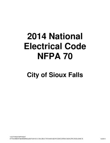
Materials used for marking shall bereflective, weather resistant andsuitable for the environment.IFC 605.11.1.1.131A21The label shall be suitable for theenvironment where it is installed.NEC 110.2154NEC20147AC Disconnect / Breaker / Pointsof ConnectionPer NEC 690.54Per NEC 690.13(B) & 690.156623Net MeterInverterBuilding/StructurePer NEC 690.544Per NEC 690.56(B)45Main Disconnect ConduitPer NEC 690.5(C)Per NEC 690.56(A)1APer NEC 690.5(C)At the location of the ground-fault protection, normally at theinverter, warning of a shock hazard (NEC 690.5[C]).5ACDisconnectPer NEC 690.17(E)NEC690.4(F) Where circuits areembedded under roofing and notcovered by PV modules, they shallbe clearly marked.47Per NEC 690.4(G)DC Disconnect/BreakerPanel Breakers/Pull BoxesPer NEC 690.53Per NEC690.13(B)Per NEC705.12(D)(4)1Per NEC 690.15Per NEC 110.27(C)Per NEC 690.35(F)DC conduit, raceways,enclosures, cable assembliesand junction boxes. Use every10’, at every turn, above andbelow penetrations, and allDC combiner junction boxesper IFC 605.11.1.4 & NEC690.31 (E)(3)Per NEC 705.12(D)(4) &NEC 690.64Per NEC690.33(E)(2)Per NEC 690.52Per NEC 690.17(E)
Section 605.11.2 Locations of DC conductors As close as possible to the ridge or hip orvalley, then as directly as possible to anoutside wall Reduce trip hazardsMaximize ventilation opportunitiesMinimize total amount of conduit on roofInstalled in metallic conduit/raceway wheninside building Conduit run along the bottom of load bearingmembers
Section 605.11.3 Roof access, pathways, and spacing requirements shallbe provided in accordance with 3.1 – 3.3 Exception: Residential structures shall be designed so that each PV arrayis no greater than 150 ft. by 150 ft. in either axis Panels shall be permitted to be located up to the roof ridgewhere an alternative ventilation method approved by the firechief has been provided
Section 605.11.3.1 Access and pathways Roof access points shall belocated in areas that do notrequire the placement of laddersover openings such as windows ordoor, and located at strong pointsof building construction inlocations where the access pointdoes not conflict with overheadobstructions such as tree limbs,wires, or signs.
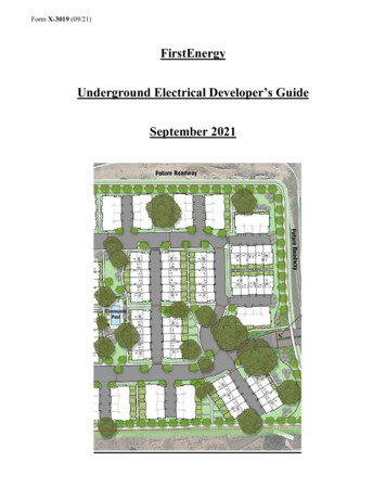
Section 605.11.3.2.1 Residential systems for 1 and 2 family dwellings With hip roof: panels shall be located in a manner thatprovides a 3 ft. wide clear access pathway from the eave tothe ridge on each roof slope where panels are located Exception: Does not apply to roofs with slopes of 2:12 or less.3 ft. pathway
Section 605.11.3.2.2 Residential systems for 1 and 2 family dwellings With single ridge: panels shall be located in a manner thatprovides two, 3 ft. wide clear access pathways from the eaveto the ridge on each roof slope where panels are located Exception: Does not apply to roofs with slopes of 2:12 or less.3 ft. pathway
Section 605.11.3.2.3 Residential systems for 1 and 2family dwellings With roof hips and valleys: panelsshall be located no closer than 18” toa hip or valley where panels are to beplaces on both sides of a hip or valley.Where panels are located on only oneside of a hip or valley that is of equallength, the panels shall be permittedto be placed directly adjacent to thehip or valley. Exception: Does not apply to roofs withslopes of 2:12 or less.
Section 605.11.3.2.4 Residential building smoke ventilation Panels installed on residential buildings shall be located nohigher than 3 feet below the ridge in order to allow forsmoke ventilation operations.3 ft
Section 605.11.3.3 Other than residential buildings. Access shall beprovided in accordance with 3.1 – 3.3 Exception: Where it is determined by the fire code officialthat the roof configuration is similar to that of a one- ortwo-family dwelling, the residential access requirements in605.11.3.2.1 – 605.11.3.2.4 shall be permitted.
Section 605.11.3.3.1 Access: There shall be aminimum 6 ft. wideclear perimeter aroundthe edges of the roof. Exception: Whereeither axis of thebuilding is 250 ft. orless, there shall be aminimum 4 ft. wideclear perimeter aroundthe edges of the roof.
Section 605.11.3.3.2 Pathways: The solar installation shall be designed toprovide designated pathways. Shall be over areas capable of supporting the live load of firefighters Centerline axis pathways shall be provided in both axes of theroof. Shall be a straight line not less than 4 ft. clear to skylights orventilation hatches Shall be a straight line not less than 4 ft. clear to roofstandpipes Shall provide not less than 4 ft. clear around roof access hatchwith at least one clear pathway to parapet or roof edge
Section 605.11.3.3.3 Smoke ventilation Arrays shall be no greater than 150 ft. by 150 ft. in either axisto create opportunities for smoke ventilation operations. Smoke ventilation options between array sections shall beone of the following: A pathway 8 ft. or greater in width A 4 ft. or greater pathway and bordering roof skylights or smoke/heatvents A 4 ft. or greater pathway and bordering 4 ft. X 8 ft. “venting cutouts”every 20 ft. on alternating sides of the pathway.
Section 605.11.4 Ground-mounted photovoltaic arrays Shall comply with 605.11 through 605.11.2 and this section. Setback requirements shall not apply to free-standing PVarrays. A clear, brush-free area of 10 ft. shall be required.
Shading Issues
Shading Design for full sun from 10 AM to 2 PM (solar time)at winter solstice Account for growth of vegetation Dirt accumulation
Incentives TIF’s REC’s Net Metering FIT’s Etc.
TIF’s Tax Increment Financing for solar PV projects Residential solar projects frequently exempt fromproperty tax Some states allow price of solar system install tooffset taxes
REC’s Renewable Energy Certificates 1 REC 1 Megawatt-hour of renewableenergy production Electrons are difficult to track Provides tracking source for who getscredit for the power produced.
Net Metering
FIT’s Feed In Tariffs (Performance Based Incentives) A payment above the market rate paid to a smallscale producer of renewable energy by a largeenergy provide Based on state requirements and individual utilitypolicyFrom solar From utility
Incentive Resources www.dsireusa.org www.energy.mn.gov
Questions ?Cari WilliametteEcoVision ElectricCari@EcoVisionElectric.com
Feb 21, 2012 · NEC (National Electrical Code) 2011 Edition unless otherwise noted. Art. 705 Interconnected Electric Power Production Sources Covers installation of one or more electric power production sources operating in par