Transcription
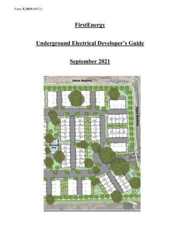
Form X-3019 (09/21)FirstEnergyUnderground Electrical Developer’s GuideSeptember 2021
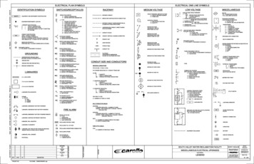
Table of ContentsUNDERGROUND ELECTRICAL DEVELOPER’S GUIDE . 4I. INTRODUCTION . 4II. DEFINITIONS. 5III. APPLICATION REQUIREMENTS . 9A. Contacting the Company. 9B. Required Information for the Company . 10C. Timeline . 10D. Location of Company Facilities . 11E. Easements . 11F. Permits . 12IV. COMPANY ELECTRICAL SYSTEM DESIGN . 12A. Electric System Design Drawing . 12B. Drawing Symbols. 12C. Responsibilities . 12D. Communications with the Company . 12E. Inspections by the Company . 13F. Design Changes . 13V. CONSTRUCTION REQUIREMENTS . 13A. One-Call Notification. 13B. Site Preparation . 14C. Excavating & Trenching . 14D. Conduit Installation . 15E. Trench Backfill . 15F. Equipment Foundations, Manholes, & Other Submersible Structure Installations . 16VI. EXHIBITS . 17A.B.C.D.E.F.G.H.I.J.K.L.M.N.O.Underground Electric Material Responsibility GuidelinesElectrical Equipment Drawing SymbolsTypical Residential Subdivision LayoutNo Exhibit – Left Open for Future UseTrenching, Conduit, & Backfill RequirementsTrenching, Conduit, & Backfill Requirements (Notes)Typical Single-Phase Box Pad Foundation Installation (1 𝛷𝛷 Transformer or 1𝛷𝛷 Junction)Secondary Pedestal Installation DetailsSecondary Handhole Installation Details – Lawn; Streetlight Handhole InstallationDetails – LawnThree-Phase Transformer Pre-Cast Concrete Foundation DetailsConcrete Flat-Pad Foundation Pad-mounted Transformer 75 to 500 kVA, ThreePhase, 34.5 kV & Below High-SideConcrete Flat-Pad Foundation Pad-Mounted Transformer 750 to 2500 kVA, ThreePhase, 34.5 kV & Below High-SideConcrete Flat-Pad Foundation Pad-Mounted Transformer General NotesManhole & Equipment Foundation Excavation Requirements SummaryNo Exhibit – Left Open for Future UsePage 2
P.Q.R.S.T.U.Manhole Installation NotesManhole Top OptionsThree-Phase Sectionalizing Enclosure Installation DetailsPad-Mounted Switchgear Foundation Installation DetailsMinimum Clearances from Structures for Oil-Filled Pad-Mounted EquipmentClearances of Pad-Mounted Equipment, Pedestals, Handholes or Manholes FromShrubs, Plants, Fences, Wall Screenings & Other ObstructionsV. Vehicular Barrier for Pad-Mounted Equipment & PolesVII. AppendixA. Customer Information FormB. Specifications Acknowledgement FormC. Final Grade Agreement FormPage 3
UNDERGROUND ELECTRICAL DEVELOPER’S GUIDEI. INTRODUCTIONThis document is published to provide specifications, information, and guidance to assistdevelopers in planning for and obtaining proper and prompt electric facilities to serveunderground developments in the FirstEnergy Service territory. The requirements detailedin this document address conduit and other mechanical structures required for theinstallation of the underground primary and secondary cables, transformers, and otherequipment necessary to serve the development. This document should be used inconjunction with the Company’s “Customer Guide to Electric Service” for the state wherethe project will be constructed. That guide details the Company’s requirements for serviceto individual locations including information on service laterals, meter installations, andcustomer equipment.The information and exhibits contained herein convey general knowledge and do notprovide every detail or every requirement. Furthermore, the information is supplementaryto, and does not intentionally conflict with the National Electrical Code, the NationalElectrical Safety Code, the Company’s current applicable tariffs, or such state andmunicipal laws, and ordinances as may be in force within the cities, towns, or communitiesin which the Company furnishes electric service. It is always necessary to comply withstate statutes, local ordinances, and the Company's standard rules and regulations on filewith the state agency that regulates public utilities. To the extent that any includedinformation contradicts any terms in the Company’s current applicable tariff, the tariffprovision shall govern.The Company reserves the right to make the final interpretation of this document and itsspecifications. The Company’s interpretation shall be binding on the customer/developer.The guidelines in this document pertain primarily to residential developments. However,the equipment, installation methods, and general system design philosophy shall also applyto commercial and industrial developments. Specific design requirements may vary forcommercial and industrial developments based on the parameters of the development, stateand local regulatory requirements, and the current applicable state tariff requirements. TheCompany engineering staff will provide specific details for these types of developments.Mandatory rules of this document are those that identify actions that are specificallyrequired or prohibited and are characterized by the terms shall and shall not.Underground Residential Development Requirements by State: Maryland - Underground Residential Developments (URD) are mandatory forresidential subdivisions of two or more building lots.New Jersey - Underground Residential Developments (URD) are mandatory forresidential subdivisions consisting of three or more building lots.Pennsylvania - Underground Residential Developments (URD) are mandatory forresidential subdivisions of five or more building lots.Page 4
New York, Ohio, and West Virginia currently have no mandates for residentialsubdivisions that require the distribution lines, secondary mains, or service lines tobe placed underground based on the number of building lots.Refer to the tariff for each Operating Company for specific details and requirements forelectric service required by the agency that regulates public utilities in the state where theproject will be constructed.II. DEFINITIONSTerms frequently used in this Guide are as defined below (for additional definitions, referto the latest edition of the National Electrical Code and the National Electrical SafetyCode): American National Standards Institute (ANSI): ANSI is an independentadministrator and coordinator of voluntary industry standards (www.ansi.org). Ampacity: Ampacity is the maximum current, in amperes (amps), that a conductoror equipment can carry continuously under the conditions of use without exceedingits temperature rating. Application for Service: Application for service is a formal request submitted bythe customer or their agent to the Company stating their desire to obtain a specificelectric service at a certain time and location. Applications may be processed by email, telephone, or fax through the Company’s Customer Service Center. Approved: Work or equipment that is acceptable to the FirstEnergy OperatingCompany or to the Authority Having Jurisdiction (e.g., electrical inspector). Authority Having Jurisdiction (AHJ): An organization, office, or individualresponsible for enforcing the requirements of a code or standard, or for approvingequipment, materials, an installation, or a procedure (e.g., electrical inspector). Backfill: Clean soil, free of large rocks (i.e., greater than two (2) inch diameter),sharp rocks, perishable material, or other debris. Clearance: Clearance is a specified minimum distance between two objects(measured surface-to-surface) to assure adequate space for safety, security, oraccess. Code: The National Electrical Code (NEC), National Electrical Safety Code(NESC), or other electrical codes or regulations in effect and that are applicable inthe area served. Company: Refers to the ten FirstEnergy Operating Companies (FEOC) operatingin: Maryland – Potomac Edison; New Jersey – Jersey Central Power & Light(JCP&L); Ohio – Ohio Edison, The Illuminating Company, or Toledo Edison;Pennsylvania and New York – Met-Ed, Penelec, Penn Power, or West Penn Power;West Virginia – Mon Power or Potomac Edison.Page 5
CReWS Work Request Number: A unique number assigned by the Company’swork management system (CReWS) for the design of a specific job. This numberwill be supplied to the developer by the Company representative from the local lineshop/service center assigned to provide the electric system design for theirdevelopment. This number should be used in any communication with yourassigned Company representative or the local line shop/service center. Note: TheCompany Contact Center (See Section III. A) does not use this number or haveaccess to it (it uses the Notification Number). Customer: Any person, partnership, association, corporation, or agency ofmunicipal, county, state, or federal government receiving any service rendered bythe Company at a contract location. This includes the party using the Company'sservice, or in applicable cases, the property owner, developer, or any party workingon behalf of the customer such as an engineer, builder, contractor, or developer. Customer's Installation (Electrical): All wiring, conduit, meter socket, servicedisconnecting devices, appliances, lighting, and other equipment installed and/orowned by the customer on the customer’s premises for the customer’s use. Theinstallation of the customer’s electrical equipment is typically governed by the NECas well as any local rules. Customer Guide for Electric Service (CGES): FirstEnergy document detailingthe Company’s requirements by state for service to individual locations includinginformation on service laterals, meter installations ( 600 V), and customerequipment. Developer: The individual, company, or organization responsible for theconstruction of the planned project of residential, commercial, and/or industrialservices set out in a recorded plot plan requiring electric service from the Company. Development (Residential): A planned project, which is developed by adeveloper/applicant, for electric service set out in a recorded plot plan for theconstruction of multiple single-family residences, detached or otherwise, mobilehomes, or apartment houses, all of which are intended for year-round occupancy, ifelectric service to the lots necessitates extending the utility’s existing distributionlines. Distribution Lines: Company lines (medium voltage and below) typically locatedin the public rights-of-way in/or along streets, alleys, highways, or on privateproperty within the subdivision for general distribution of electric service tocustomers. The electrical distribution system collectively includes the primary,secondary, and services. Environmental Protection Agency (EPA): The EPA is an agency of the U.S.federal government that protects human health and the environment by writing andenforcing regulations based on laws passed by Congress (www.epa.gov). Federal Aviation Administration (FAA): The Federal Aviation Administration isthe national aviation authority of the United States. An agency of the United StatesDepartment of Transportation, it has authority to regulate and oversee all aspectsPage 6
of American civil aviation (www.faa.gov). FAA requires notification whenworking near aviation facilities and may impose pole placement or pole heightrestrictions to maintain aviation safety. . Final Grade: Final grade shall refer to the eventual permanent ground level afterall finished grading, paving, and landscaping is completed. Final grade shall beused when determining minimum clearances for overhead and undergroundfacilities. Line Extension: The extension of the Company’s facilities (including but notlimited to poles, fixtures, transformers, wires, cables, vaults, foundations, andappurtenances) necessary for delivering electrical energy from the point where aline extension connects with and receives energy from an existing transmission ordistribution source, which is the nearest and suitable source, to the new service line,which will provide electric service to the customer. Line extension rules and costsare further defined in each Operating Company’s Tariff with the state. Listed: Equipment, materials, or services included in a list published by anorganization (e.g., UL Listed) that is acceptable to the Authority HavingJurisdiction and concerned with evaluation of products or services, that maintainsperiodic inspection of production of listed equipment or materials or periodicevaluation of services, and whose listing states that the equipment, material, orservices either meets appropriate designated standards or has been tested and foundsuitable for a specified purpose. National Electrical Code [NFPA 70] (NEC): The NEC is a set of nationalregulations that govern the installation of electrical equipment located on thecustomer’s side of the point of service. All NEC references refer to the latest stateadopted version of the NEC. National Electrical Safety Code [IEEE C2] (NESC): The NESC is a set ofnational regulations that govern the installation, operation, and maintenance of theelectric supply and communication lines. NESC applies to equipment located onthe electric utility’s side of the point of service. All NESC references refer to thelatest version of the NESC. Notification or Design Request (DR) Number: A unique number assigned by theCompany used for designing, tracking, constructing, and billing of a specific jobby the Company Contact Center. This number should be used in anycommunication with the Company Contact Center. (See Section III. A.) Occupational Safety & Health Administration (OSHA): is a federal governmentagency in the Department of Labor to maintain a safe and healthy workenvironment (www.osha.gov). Point of Service: Point of service is that point where the Company's equipment orconductors connect to the customer’s conductors or equipment of the facility. The“point of delivery” is commonly known as the “point of service.” Primary: Company conductors (cables) connected to low-side of a distributionsubstations that provide medium voltage power to high-side of a distributionPage 7
transformers located near the customers premises. Typically defined by theCompany as voltage ranging between 2.4 kV to 34.5 kV. Secondary/Secondary Main: conductors (cables) connected to the secondaries ofdistribution transformers from which customers services are supplied ( 600 V). Select Backfill: Select backfill is graded sand, stone dust, limestone dust, earth ortopsoil that is free from large or sharp objects, rocks, scrap building material, orcorrosive material. Materials that “set up” such as fly ash, culm and foundry wasteare not acceptable. It is used to backfill a trench for buried conduit and is used toensure the future integrity of the conduit or direct buried electrical cables. Service: Delivering electric energy from the Company’s distribution system to asingle point of connection at a customer's premises. Service Lateral: A set of underground service conductors extending from theCompany’s electric distribution facilities, including any risers at a pole or otherstructure or from transformers, handholes, or pedestals to the first point ofconnection to the service entrance conductors in a terminal box, meter, or otherenclosure with adequate space, inside or outside the building wall. Service Territory (electric): Service territory is a defined area in which a givenelectric utility can legally provide service. The area is governed by a set ofagreements and maps on file with the state agency that regulates public utilities. Tariff: Tariffs are a set of rate schedules and riders, rules, and regulations forproviding electric service throughout each Operating Company’s service territory.The applicable Company Tariffs are filed with and approved by the state agencythat regulates public utilities. Temporary Electrical Service: A service line, meter, and/or other work suppliedby the Company to the customer for electric service for construction purposes orfor a limited duration, typically no longer than one year, and delivered to a singlepoint through one meter. Underground Equipmento Transformer Box Pad 15-inch: 37" X 43" X 15" fiberglass box pad with 26"X 30" opening for single-phase pad-mounted transformers, transformer deferralcabinets, and single-phase sectionalizing enclosures. Note: The front of boxpad is indicated on the top of the box pad and area for placement of conduit isindicated with a line on each side of the opening. (See Exhibit G.)o Transformer Box Pad 32-inch: 37" X 43" X 32" fiberglass box pad with 26"X 30" opening for single-phase pad-mounted transformers, transformer deferralcabinets, and single-phase sectionalizing enclosures. Note: The front of boxpad is indicated on the top of the box pad and area for placement of conduit isindicated with a line on each side of the opening. (See Exhibit G.)o Three-Phase Transformer Pads: Precast concrete foundations as specified inExhibit J or concrete flat pads as specified in Exhibits K, L, and M.Page 8
o Handhole Small Lawn (600 V): Handhole, lawn type, Tier 5, HDPE, 12" X20" opening X 15" depth, includes flat cover, also available with a 15” domedcover. Mounted at grade. (See Exhibit I.)o Handhole Medium Lawn (600 V): Handhole, lawn type, Tier 5, HDPE, 17"X 30" opening X 17" depth, includes flat cover. Mounted at grade. (See ExhibitI.) Handhole Streetlight Lawn (600 V): Handhole, lawn type, HDPE, 9” roundopening, 9” depth, includes flat cover. Mounted at grade. (See Exhibit I.) Pedestal: Fiberglass secondary junction enclosure, stake-less pedestal, with 3”flanged base, overall dimensions 18" X 22" X 30", above ground dimensions9" X 14" X 18". (See Exhibit H.) Three-phase Junction/Sectionalizing Enclosure: pad-mounted enclosurecontaining multi-position primary (15 kV, 25 kV, or 35 kV) junctionmodules/bus for all three-phases, typically fiberglass with 19.5” integral base,88” W x 50” D X 49.5”H, flip up lid. (See Exhibit R.) Single-phase Junction/Sectionalizing Enclosure or Transformer DeferralCabinet: pad-mounted enclosure containing multi-port primary junctionmodule/bus (15 kV, 25 kV, or 35 kV) for one phase, typically fiberglass cabinetmounted on single-phase transformer box pad, 35.5” W X 28” D X 28”H, flipup lid. (See Exhibit G.) Manhole Small: Precast concrete manhole, 2-piece, base with internaldimensions 6’ X 8’ X 7’, variable cover designs based on use, H20 with impact.(See Exhibits N, P, and Q.) Manhole Large: Precast concrete manhole, 2-piece, base with internaldimensions 6’ X 12’ X 7’, variable cover designs based on use, H20 withimpact. (See Exhibits N, P, and Q.)III. APPLICATION REQUIREMENTSA. Contacting the CompanyThe developer shall contact the Company Contact Center concerning the project by callingthe local operating company 800 number listed below. A Company representative will beassigned to your project from the local line shop/service center.Operating Company Contact Center Numbers: Jersey Central Power & Light:Met-Ed:Mon Power:Ohio Edison:Penelec:Penn Power:Potomac Edison:The Illuminating Company:Toledo Edison:West Penn Power:Page -447-3333800-686-0021
B. Required Information for the CompanyThe developer shall provide the Company with a local building authorityapproved/recorded copy of the customer plot plan drawn to scale including all easementsfor other utilities/facilities, crossroads, proposed structures, wells, septic, decks,drives/parking areas, pools, ponds, planned major landscape changes and futuredevelopment areas, and any other known or proposed obstructions that may interfere withthe Company supplying electric service.Electrical loading information shall also be required for the design. For residentialstructures, this would include typical square footage, load characteristics, and fuel options(i.e., natural gas, electric, or other) for heating and hot water. Also include informationregarding voltage and load requirements for any non-residential subdivision facilities, suchas pumping stations, swimming pools, community buildings, etc. The companyrepresentative may require more detailed information for commercial and industrial loadsor commercial or industrial developments to establish accurate electric load profiles.If the project will be developed in phases, the developer shall provide a master plan drawingwhich details the total area to be developed, including all future streets, and a proposedtimeline for the construction of the various phases.The subdivision plot plan drawings shall be provided in both hard-copy full-size print formfor design purposes and electronically in .dwg format so they can be readily added into theCompany GIS land base.For street lighting applications in conjunction with the development, the developer shallcontact the Company Representative for details. (Note that street lighting requirements arefrequently under the control of the local jurisdiction and the specific requirements may notbe known at the time the electric system design is being established by the Company. Inthese situations, the Company may require the installation of conduit stubs out of manholes,handholes, or transformers to allow for the establishment of a future electric systemsupplying the street lighting system required by the local jurisdiction. This will typicallyrequire a conduit stub from one or more Company equipment locations. The Companymay also require the stub to be extended and terminated in a handhole or pedestal.)C. TimelineAll required information shall be provided at least sixteen (16) weeks prior to the dateservice is required for residential subdivisions of 20 lots or less. For residentialsubdivisions between 20 and 200 lots, this information shall be provided at least twentyfour (24) weeks prior to the date service is required.Larger subdivisions or those with multiple phases of construction, commercial, municipal,or other large loads may require additional time. Additionally, more complex subdivisionsdesigns (varying lot sizes, non-rectangular lots, multiple elevation changes, multiplecommercial/municipal loads, etc.) may require a timeframe much longer than those quotedabove. Contacting the Company during the initial planning stages of these largersubdivisions will help to ensure the design and installation of the electric system occurs ina timely manner.Page 10
D. Location of Company FacilitiesThe required location of Company underground facilities in residential developments is thefront lot line with each dwelling served by a separate service. The specific location of theunderground electric facilities shall be chosen to avoid open drainage ditches, creeks,marsh areas, areas that are prone to flooding, areas of steep terrain, or other areas that areenvironmentally sensitive or may hinder construction or operation of the electric system.Additionally, the location of Company underground facilities, including conduit,manholes/handholes, and foundations, shall be chosen so that the area is accessible and hasadequate working space for the equipment and personnel needed to install and maintain thefacilities.Any changes to the location of the Company facilities shall be approved by the Company’sEngineering Section prior to the installation of those facilities. Future access to thesefacilities shall not be impaired by landscaping, fencing, guard rails, grading, buildings, orother structures or barriers. (See Exhibits T and U.)For commercial and industrial developments, the Company will develop a constructionplan which incorporates the most practical layout, taking into consideration safety,reliability, maintenance requirements, future access, economics, customer loadrequirements, and the design of the development including the design requirements of theindividual commercial or industrial services. The location of the underground facilities,the location of the service equipment, the right-of-way requirements, and other designaspects may vary significantly from the requirements for residential developments.Although there may be significant design differences for these types of developments, theconduit, manholes, and equipment foundations utilized will be the same as those found inthe Exhibits and will be installed in the same manner.E. EasementsAll Company-owned equipment within the subdivision shall be located within the boundsof a recorded easement on private property. One blanket utility easement for the entiredevelopment shall be obtained from the developer (i.e., property owner) and be recordedon the plat for the subdivision by the developer. The individual FirstEnergy OperatingCompany shall be specifically named in the easement. The right-of-way agreementcovering the use of the easement is obtained from the property owner and is legallyrecorded against the development as a permanent record by the Company. Right-of-wayagreements shall be properly executed and recorded prior to selling any individual lots.Easements required for Company underground facilities are ten feet in width unlessotherwise specified by the Company. Along front lot lines, the easement extends intoprivate property from the street right-of-way. Along the side lot lines, the easement istypically split evenly between the adjacent lots. (See Exhibit C for a typical residentialsubdivision layout with easements.)Easements shall be free and clear of any structure that impedes access. This includesstructures independent and separate from the main structure or portions of the mainstructure that protrude beyond the foundation such as porches, stoops, bay windows, orother such structure extensions that project into or over the easement.Page 11
F. PermitsThe developer shall also arrange for expediting the acquisition of any local (e.g., municipalor township), county, or environmental permits, including but not limited to the following:1.2.3.4.5.6.7.8.9.Freshwater & Tidal Wetlands,CAFRA/Waterfront Development,Soil Erosion & Sediment Control,Stream Encroachment,Department of Transportation (DOT) Road Crossings,Turnpike Road Crossings,Army Corps of Engineers Navigable Water Crossings,Railroad Crossings or Occupation,Federal Aviation Agency & State DOTs Permits for work near aviation facilities.The developer shall be required to produce evidence of such permits that is deemedsatisfactory by the Company.IV. COMPANY ELECTRICAL SYSTEM DESIGNA. Electric System Design DrawingThe developer shall receive the Company electrical layout design drawing(s) prior tobeginning trenching or equipment foundation, junction, handhole, manhole, and pedestalsite preparation.B. Drawing SymbolsThe location of the conduit, transformers, manholes, handhole/pedestal, and otherequipment and structures necessary for the installation of the electric system serving thedevelopment shall be shown on the drawing supplied by the Company. The facilities willbe represented by the symbols shown on Exhibit B.C. Responsibilities1.Details on the responsibilities of the developer and the Company for the variousfacilities needed for the installation of the electric system are included in Exhibit A.2.The installation of these facilities shall comply with all Company standards andrequirements as detailed in the attached Exhibits.D. Communications with the Company1. The developer shall reference the CReWS Work Request number in all correspondencewith their Company representative or the local service center/line shop. The Companyrepresentative shall supply the developer with this number.2. The developer shall c
National Electrical Code [NFPA 70] (NEC): The NEC is a set of national regulations that govern the installation of electrical equipment located on the customer’s side of the point of service. All NEC references refer to the latest state adopted version of the NEC. National Electrical
