Transcription
Proceedings of the ASME 2019International Design Engineering Technical Conferencesand Computers and Information in Engineering ConferenceIDETC/CIE2019August 18-21, 2019, Anaheim, CA, USAIDETC2019-97640COMPUTATIONAL DESIGN OF SCHEDULING STRATEGIES FOR MULTI-ROBOTCOOPERATIVE 3D PRINTINGLaxmi PoudelDepartment of MechanicalEngineeringUniversity of ArkansasFayetteville, ARWenchao ZhouDepartment of MechanicalEngineeringUniversity of ArkansasFayetteville, ARABSTRACTCooperative 3D printing (C3DP) is a novel approach toadditive manufacturing, where multiple printhead-carryingmobile robots work together cooperatively to print a desiredpart. The core of C3DP is the chunk-based printing strategy inwhich the desired part is first split into smaller chunks, and thenthe chunks are assigned to individual printing robots. Theserobots will work on the chunks simultaneously and in ascheduled sequence until the entire part is complete. Thoughpromising, C3DP lacks proper framework that enablesautomatic chunking and scheduling given the available numberof robots. In this study, we develop a computational frameworkthat can automatically generate print schedule for specifiednumber of chunks. The framework contains 1) a randomgenerator that creates random print schedule using adjacencymatrix which represents directed dependency tree (DDT)structure of chunks; 2) a set of geometric constraints againstwhich the randomly generated schedules will be checked forvalidation; and 3) a printing time evaluation metric forcomparing the performance of all valid schedules. With thedeveloped framework, we present a case study by printing alarge rectangular plate which has dimensions beyond whattraditional desktop printers can print. The study showcases thatour computation framework can successfully generate a varietyof scheduling strategies for collision-free C3DP without anyhuman interventions.Keywords: Cooperative 3D printing, Task scheduling,Multirobot systemNOMENCLATURE𝐴𝑆#,% (𝑡)𝑆𝑉#,% (𝑡)ASc (t)1Accessible space of robot, i, at time, tSwept volume of robot, i, at time, tOccupied space by printed chunk at time, tZhenghui Sha1Department of MechanicalEngineeringUniversity of ArkansasFayetteville, AR1. INTRODUCTIONAs additive manufacturing (AM) transitions from rapidprototyping to digital manufacturing over the past years, thecurrent cost structure of the technologies is too expensive to beviable for mainstream manufacturing adoption. One criticalfactor of the cost structure for adoption is the scalability issue, interms of both print size and printing speed. Extensive researchhas been performed on increasing the size of the printer forprinting larger parts, e.g., BAAM (big area additivemanufacturing) system developed by Oak Ridge National Lab[1] and Sciacky EBAM 300 machine. Also, there are otherresearches on improving printing speed with multiple extruders.For example, Project Escher makes the use of multiple 3D printheads for massive jobs, where each print head acts like a separateprinter but works in parallel on different areas of the same part[2]. It was demonstrated that the printing time can besignificantly shortened with five extruders. Although the buildvolume is large, it is still limited to the size of the printer.Similarly, Jin et al. presented a concept of concurrent fusedfilament deposition, where multiple printing extruders areutilized simultaneously to print individual layer of a desired part[3]. They have developed an optimization model to minimize theprinting makespan and developed a toolpath allocation andscheduling methodology for multiple extruders, where theyallocate portion of each layer to individual extruders. They wereable to reduce each layer printing time by as much as 60% usingthree extruders. While promising, the issue of scalability is notproperly addressed as the demonstration has only been doneusing few extruders. Since the printing takes place in an enclosedbox, this approach faces similar limitation of print size as ProjectEscher. Therefore, there is a limit on the maximum number ofextruders that can be used in this system as well as the limit onthe size of a part that can fit in the build volume.Corresponding author: zsha@uark.edu1 2019 by ASME
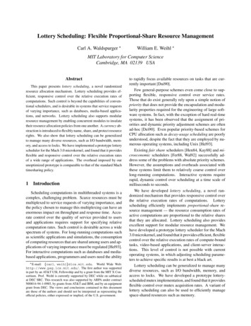
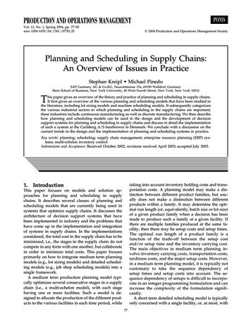
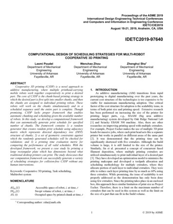
While some of the aforementioned approaches made goodprogress on tackling the problem of print time and print size, theprint quality might be impacted. A larger printer with largeextruders can shorten the print time and accommodate larger partbut the print quality will lower as a result of coarser resolution.In order to achieve a balance for this “impossible triangle” ofprint quality, print time, and print size, we have developed theSwarm 3D Printing and Assembly (SPA) platform, where aswarm of printhead-carrying mobile robots work simultaneouslyto print and assemble large objects [4]. One of the most importantfeatures of SPA, that distinguishes itself from traditional layerbased 3D printing system is the chunk-based printing strategy –a 3D model of a desired part is divided into smaller chunks firstand each of these chunks are assigned to individual printingrobots. Each individual robot prints one chunk at a time, butmany printing robots work in parallel, and layer by layer for eachchunk as illustrated in the Figure 1. Therefore, a large numberof printing robots can be employed to print a large part. Since theprinting can be parallelized, i.e., multiple chunks can be printedsimultaneously, the total print time can be significantly reduced.chunks on the opposite side of central row as shown in theFigure 2. Similar to the central row, robots print alternate chunksfirst and once complete, move over to print the remaining chunksfilling the gaps between previously printed chunks. This processalternates and continues until the entire part is finished.Figure 2: SPAR3 strategy illustrationFigure 1: Chunk-based Cooperative 3D printingIn our preliminary work, we have developed a chunk-basedslicer in order to slice STL objects so that two 3D printing robotscan work on printing the part simultaneously to reduce the totalprint time [5]. To achieve cooperative 3D printing (C3DP), thepart is split into chunks with a sloped interface between them andthe mechanical properties of the chunk-based parts studied in ourprior work [6] shows that the chunk-based 3D printed part hascomparable tensile strength to traditional layer-based 3D printedpart. To scale C3DP to multiple robots in [7], we developed aheuristic-based scaling strategy, Scalable Parallel Array ofRobots for 3DP (SPAR3), which enables a large number ofmobile 3D printers to work cooperatively to finish a printing jobwithout colliding with each other, as illustrated in Figure 2. First,two robots start working on the alternate chunks in the centerrow as shown in Figure 2. These robots then move over to printthe remaining chunks in the same row in order to fill the gapsbetween the initially printed chunks. Once complete, activerobots retreat to work on the next row of chunks. Meanwhile, thetwo additional robots, waiting for the completion of the centralrow of chunks, become active and start printing second row ofWhile a print schedule based on this simple heuristic for asimple geometry with finite number of robots might give us goodresults, as the number of chunks increases, the heuristics mightnot provide the best solution as the large part of design spaceremain unexplored. For example, if we increase the number ofchunks from 20 to 100, ignoring the constraints, the possiblenumber of print schedule increases exponentially. This wouldresult in 100! possible plans just for sequential printing. Addingparallel printing (multiple chunks being printed simultaneously),increases the number of potential plans even more. So, we needto ensure that these larger design space unexplored by theheuristic approach is traversed thoroughly. In order to do so, anew approach needs to be developed so that, we can search forprint schedules for complex geometries, which often cannot behandled by human heuristics, that can maximize the use of theresources in hand. A computational framework that can betransformed in algorithms so as to automatically generate manydifferent valid scheduling strategies is essential to thedevelopment of scalable C3DP. Therefore, the researchobjective of this paper is to establish a computational frameworkthat can explore larger design space that would otherwise remainunexplored and generate valid scheduling strategies from thatspace. In order to do just that, in this paper, we develop a newalgorithm to automatically generate printing schedules for agiven number of robots and evaluate the validity of the generatedschedules based on the geometric constraints produced by bothprinting robots and chunks. Once validated, we can makecomparison between the printing schedules heuristicallygenerated with the ones computationally generated, using theprinting time evaluation metrics.2 2019 by ASME
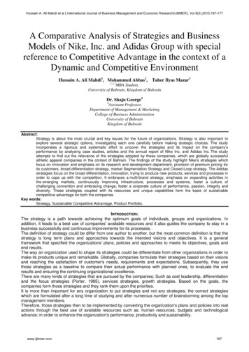
The remaining of the paper is organized as follows. Section2 presents the related work and the research gap that this paperaims to fill. Section 3 explains the general research approach andthe computational framework, which includes the model forC3DP, geometric constraints and the time evaluation metrics. Acase study is presented in Section 4 that demonstrate the utilityand performance of the proposed framework. Finally, result ofthe case study and the discussion are presented in Section 5,followed by conclusion in Section 6.2. RELATED WORK AND RESEARCH GAPAlthough the SPA platform presents many benefits, as a newapproach to digital manufacturing, it brings additionalchallenges in task scheduling (i.e., to optimally generate aprinting sequence that minimizes the total time of printing, in ourcase) and task allocation (i.e., to assign chunks to individualrobots). This makes it an integrated planning and scheduling(IPPS) problem. The addition of 3D printing as a manufacturingprocess compounds the difficulty of IPPS problem further,making it a NP-hard problem to solve [8, 9]. IPPS has widelybeen researched ever since Chryssoulouris et al. first presentedthe concept of integrating the process planning and schedulingproblems [10, 11]. Though many optimization methods(simultaneously optimize both planning and schedulingfunctions) have been presented over the years using differentapproaches such as meta heuristics approach (e.g., GeneticAlgorithm [11-14]) and agent based approaches (e.g., ParticleSwarm Optimization [9] and Ant Colony Optimization [15]), theproblem definition is limited around the job shop schedulingproblems, where multiple jobs needs to be scheduled in multipleworkstations. Scheduling plans for robotic applications is notstudied in most of the related research. Robotic application addsmore complexity to the problem as it necessitates the generationof motion trajectories for multiple mobile robots. Petrovic et al.performed a pioneering study to optimize schedule plans usingchaos theory with particle swarm optimization (cPSO) algorithmand used it to generate motion trajectories followed by mobilerobots in IPPS problem[9]. Though the work presents anddemonstrates the motion trajectories of mobile robots, scope ofwork does not include collision detection between the mobilerobots, where spatiotemporal constraints needs to be developedand applied.Similarly, multi-robot systems (MRS) is another active fieldthat deals with task assignment and collision-free scheduling ofmultiple robots. Koes et al. presented a novel framework and acentralized anytime algorithm with error bounds to addressmulti-robot scheduling and task allocation problem as mixedinteger linear programming (MILP) problem, which couldoutperform greedy heuristics, and market-based approacheswhich separates scheduling and task allocation [16]. In a relatedstudy, a connectivity graph along with Liaison method was usedto generate sequence for multi-robot assembly by Mishra et al.[17]. Parallel execution of assembly sequences for multi-robotwork cell was studied by Park et al. [18]. While they developedconstraints to avoid infeasible assembly sequence, no constraintswere developed in order to avoid robot-to-robot collision as onlysingle gripping robot was used for demonstration. A novelalgorithm, Terico, was developed to generate schedule fulfillingtemporospatial constraints for multi-robot system by Gombolayet al. [19]. This algorithm could perform near-optimal taskassignments and schedule up to 10 robots and 500 tasks in lessthan 20 seconds on average but lacks clarity on how thealgorithm behave as the number of robots is greater than 10. Wanet al. proposed a newly developed planner for finding optimalassembly sequence to assemble objects and demonstrated theresults by optimally scheduling Soma cube [20]. While thescheduling approach of this work could be applicable, the workis only applicable to single robots, which eliminates complexityassociated with the collision between working robots.All of the literature discussed above, both in the field ofIPPS and MRS, and other extant literatures provide differentelegant solutions to multi-robot planning and schedulingproblem and though at first glance it might seem like theproblems addressed are similar to the problems facing the SPAplatform, it is not the case. The literature in MRS are mostlyfocused on solving discrete problems, i.e., problems that can besolved by taking discrete number of steps, e.g., pick and placeassembly, patterns formations, search and rescue, etc. While theliterature in IPPS are mostly focused on job shop type ofproblems, where multiple machines (usually fixed) orworkstations are available and multiple tasks needs to becompleted. The problem of C3DP, on the other hand, is a uniqueblend of these two types of aforementioned problems. Thiscomplicates the problem, as not only do we have to worry aboutthe planning and scheduling of chunks but also collisionsbetween the mobile robots and their motion planning while doingso. In addition to this, the integration of 3D printing makes themanufacturing process continuous, where material iscontinuously deposited temporospatially until a desired part ismanufactured. There is no existing method that could take adesign of a desired part computationally and implement 3Dprinting using multiple printing robots. Thus, there is a clear gapfor generating viable and valid scheduling strategies for C3DP.Moreover, different chunking methods of C3DP will result indifferent temporospatial constraints that could be even morecomplicated than our previously proposed slope angle-basedchunking. Thus, a general framework is needed to handle paralleltask scheduling for continuous 3D printing process with complextemporospatial constraints.3. RESEARCH APPROACH3.1 The Computational Framework for C3DPSchedulingPrior to jumping at explaining the computationalframework, it is paramount that we explain the entire printingprocess of C3DP. We approach the continuous problem of C3DPby first discretizing the entire process using a chunk-basedapproach. Doing so converts the continuous C3DP into multistage discrete process as illustrated in Error! Reference sourcenot found. such that there are inter-dependencies betweenmultiple stages.3 2019 by ASME
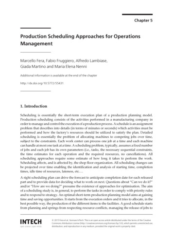
Figure 3: Flowchart depicting the different stages of C3DP after discretizingIn order to achieve C3DP, first, a part is divided into smallchunks. Once the chunk division is complete, a print schedule isgenerated for a given number of printing mobile robots. Thescheduling is represented using a Directed Dependency Tree(DDT) where the nodes represent the chunks and the edgesrepresent dependency between the nodes as shown in Figure 4[7]. A DDT can define both print schedule and the dependencyrelationships between the chunks at the same time. The order oflayers from top to bottom represents the print order, and thenumber of chunks at each layer represents the number of printtasks that can be done in parallel.In the proposed computational framework, a random DDTis first generated, which contains the scheduling informationsuch as chunk dependencies and number of sequence (i.e., thedepth of a tree). Then, the path planning is done for the generatedDDT. Prior to printing, geometric constraints validation will beperformed. The geometric constraints validation will ensure thatno collision takes place between the printing robots (R2Rcollision) and between the printing robots and printed parts (R2Pcollision). This entire process of C3DP and the computationalframework of automatically scheduling are depicted in Error!Reference source not found.3.2 Random Generation of Print SequenceFor random generation of C3DP schedules, a part is firstdivided into n chunks by a chunker. Once the chunking iscomplete, a sparse adjacency matrix of dimension 𝑛 𝑛 isgenerated with binary values of either 1 or 0 at random indices.Value of 1 represents a dependent relationship between twochunks and 0 represents absence of dependency between thechunks. For example, if a part is divided into 12 chunks(numbered 0-11), one of the generated dependency matrices (andthe corresponding dependency tree) might look like the oneshown in Figure 4. Both the adjacency matrix and the DDTpresent the same information but only represented differently.The chunks with no dependency in the matrix will be placed atthe root node at the top of the dependency tree (chunk 0 andchunk 1). The chunks that depend on either one of those chunks(or both) will be placed below the root nodes (chunk 2 andchunk3). This method of adding chunks as nodes is continueduntil the end of rows in the adjacency matrix. In order tominimize the number invalid trees and impossible printingscenarios, following rules are created and will be implementedwhile generating the matrix:1) It is important that the generated matrix results in printschedule that has a structure that is layered and not cyclic. Acyclic dependency could result in a scenario where twochunks could have direct or indirect dependencies on eachother. For example, in the dependency tree shown in Figure4, currently Node-2 has two dependencies, Chunk-0 andChunk-1. Allowing cyclic dependency results in thescenario, where Chunk-1 could have dependency on Chunk2. This can result in stalemate situation where Chunk-2cannot be printed prior to Chunk-1 and Chunk-1 cannot beprinted prior to Chunk-2. In order to check whether thecreated matrix has cyclic dependency, we take transpose ofthe generated matrix and calculate Hadamard product (alsoknown as entry wise product) of the two matrices. If theresult of the Hadamard product is not a zero matrix, the4 2019 by ASME
generated matrix is ignored as it contains cyclicdependencies between the chunks. Otherwise, the generatedmatrix is passed on to the next stage.2) Transitive reduction is used to eliminate double dependencybetween two chunks. For example, if Chunk-8 hasdependent relation with Chunk-1 via Chunk-2, there is noneed of edge between Chunk-8 and Chunk-1.These specified criteria are ingrained into the algorithm thatgenerates random C3DP schedules and thus the generated treewill not violate the rules.Figure 4: Adjacency matrix representing the directed dependency tree3.3 Geometric ConstraintsThe generated DDT regulates both the printing sequence and thedependency relationships between the chunks. However, thegenerated DDT might not be valid due to potential physicalconstraints, i.e., the DDT might represent a printing sequencethat results in collision between either printing robots (R2Rcollision) or the printed parts and the printing robots (R2Pcollision). For example, the print sequence might have twochunks adjacent to each other, being printed simultaneously,which would result in collision between the printing robots. Suchscenarios need to be avoided prior to implementing the printschedule. Therefore, a set of constraints must be formulatedwhich a printing strategy can be evaluated against to reject theprint strategies that could result in collision, and only accept thecollision-free print strategies. These constraints can then serve asa sufficient condition for the validation of a printing strategy, i.e.,if a printing strategy doesn’t violate any of the constraints, theprinting strategy is valid and would result in collision-free C3DP.So, any valid printing strategy must satisfy the following:1) A robot, i, does not collide with already printed chunks. Thisconstraint can be mathematically represented using theconcept of accessible space of robot (ASR,i), which is 3Dspace occupied by the printing robot, i, and occupied spaceof printed chunks (ASc), which is 3D space that is occupiedby the chunks that are already printed. The mathematicalformulation of this constraints is presented in Equation (1).𝐴𝑆#,% (𝑡) 𝐴𝑆. (𝑡) , 𝑖 1,2,3 , 𝑛(1)2) A robot, i, does not collide with any other robot, j, at anytime during the entire printing process. This can bemathematically represented using the concept of sweptvolume, which is the entire 3D space covered by the printingrobot as it prints an assigned chunk. The differentiationbetween the accessible space and the swept volume of arobot is presented in Figure 5. The mathematicalformulation of this constraints is presented in equation (2).𝑆𝑉#,% (𝑡) 𝑆𝑉#,6 (𝑡) ,(2)𝑖 1,2,3 , 𝑛; 𝑗 1,2,3 , 𝑛; 𝑗 𝑖,The discretization of C3DP makes it possible to check thegeometric constraints at different time resolution. The check forpotential R2R collision is done in the following manner: The default check is done at chunk level, i.e., the collisionbetween the two printing robots is checked while they workon their respective chunks. Though this check rejects all theinvalid print schedule, it also could potentially reject somevalid schedules. This happens when the swept volumes ofrobots overlap with each other, but the robots might notoccupy same exact location at same time. For example, iftwo robots are working on adjacent chunks, their sweptvolume will overlap but they might not arrive at theoverlapping location at the same time. In order to reduce the possibility of false negativesmentioned above (overlapping of swept volume but nocollision), the check can be done at layer-level, i.e., thecollision between two printing robots is checked while theywork on individual level of their respective chunks. Similarto the check at chunk level, this rejects all the invalid, butsome valid schedules could be rejected as well. To further ensure that false negative has not taken place, wecan run check at line-level or G-code level, where a checkfor collision is done at each G-code line. Though accurate,this is computationally taxing as it requires more frequentchecks whereas, the chunk-level check requires leastfrequent checks.Thus, first chunk-level check is conducted, if the results arevalid, we move on to the next print sequence. Otherwise, layerlevel check can be conducted. Similarly, if valid, we can moveon to the next layer. Otherwise, line-level check can beconducted. If this produces invalid result, the schedule isdiscarded as an invalid print schedule. Thus, any generated printstrategies can be validated using the geometric constraintspresented in Equations (1) and (2) to ensure that the collisiondoes not take place between the printing robots as well asbetween the printed parts and printing robots.3.4 Time Evaluation using DDTIn our previous work [7], we presented the idea of usingDDT to calculate the total print time of a printing schedule. Thenumber of rows in the trees (i.e., the tree depth) represents thetotal number of print sequence, i.e., the number of printing stepswhereas, the column or the width of the tree represents the5 2019 by ASME
number of robots used for parallel printing. For instance, theDDT presented in Figure 4, depicts a print schedule with fourprinting sequence and utilizes maximum of four robots (but onlytwo are needed in two initial sequence). In order to calculate theprint time, a recursive function is presented in Equation (3).𝑇(𝐷, 𝑐% ) max{[𝑇(𝐷, 𝑐B ) 𝑐B 𝑐% . 𝑑𝑒𝑝𝑠], 0} 𝑡(𝑐% )𝑖 1,2,3 . 𝑛, and 𝑚 1,2,3, 𝑁%(3)where, 𝑁% is the number of dependency chunks of 𝑐% . In Equation(3), 𝑇(𝐷, 𝑐% ) is the time it takes to print chunk, 𝑐% , in a given DDT,𝐷, which is the sum of the time it takes to print the single chunk𝑐% , i.e., 𝑡(𝑐% ) and the time it takes to print all of its dependencies,𝑐B , i.e., 𝑇(𝐷, 𝑐B ). This equation can be generalized to calculatethe total print time of a DDT as shown in Equation (4), where,𝑇PQPRS is the total time needed to print the entire sequence of 𝐷,with 𝑛 chunks. This is equal to the sum of the time it takes toprint the last chunk, n, and time it takes to print all of itsdependencies, m.𝑇PQPRS max({𝑇(𝐷, 𝑐B ) 𝑚 [0, 𝑛 1]})2) Once a chunk is printed, printing robot moves to the locationof next chunk immediately. The travel time between thechunks is ignored in the calculation.The output of chunker (i.e., the chunking algorithm) consistsof eight coordinate points, four coordinates for four corners ofthe base and the other four coordinates for the top corners of thechunks. In addition to this, chunk number is also outputted. Theeight coordinates are used for checking constraints and the chunknumber is used for generating adjacency matrix as well as aDDT. The following steps were taken to implement thecomputational framework in this case study:(4)4. CASE STUDYTo demonstrate how the computational framework works,we present a simple illustrative case study. There are twoprimary reasons for using a simple model to demonstrate thecomputational framework: 1) the use of simple model allowsaudience to focus on the actual computational framework ratherthan getting distracted by the complexity of the model (and itschunking) and jargons associated with the additional complexity.2) The use of simple model allows audience to visualize thesloped-interface chunking strategy in an intuitive manner. Thechunking of simple geometry results in regular geometric shapeswhich makes it much easier to understand and visualize how thegeometric constraints translate into actual physical constraints.The part considered for this case study is a rectangular blockfor demonstration purpose. The dimensions of block are100cm 80cm 1.5cm and has a total volume of 12,000 𝑐𝑚X .The block is printed using PLA. The rectangular block and theresulting chunks (chunked using sloped-interface chunkingmethod) obtained after chunking is presented in Figure 5. Fourrobots are used for this case study. In addition, the followingassumptions are made:1) The chunks created have equal volume and can only haveone of the shapes shown in Figure 5. If different chunkingstrategy is chosen for chunking, the shape of the chunkscould be different. Since the volume is equal, and theprinting parameters are the same for all the printers, the timeto print each chunk is assumed to be equal for simplifyingthe evaluation of print time. Assuming the material isXdeposited at the rate of 16 𝑚𝑚 Y𝑠 using a 0.4 𝑚𝑚 nozzle,the estimated time to print a chunk is 10.42 hours.Figure 5: Rectangular block showing the chunks line, exploded viewof the chunks that combine to make a rectangular block and top viewof exploded chunks with chunk number marked1) Generation of print schedule for rectangular blockThe result of chunking is shown in Figure 5. The algorithmthen generates adjacency matrix that meets all the predefinedcriteria specified in Section 3.2. This generated matrixrepresents a print schedule. The next step is to check the validityof the print schedule using the geometric constraints presentedin Section 3.2.Figure 6:( a) Accessible Space of robot (reduced to z-stage) (b) SweptVolume of robot while print a chunk. Position of robot shown atdifferent chunk corner coordinate2) Validation check of generated schedules using geometricconstraintsIn order to check the geometric constraints, the sweptvolumes (SV) of the active robots are defined as shown in the6 2019 by ASME
Figure 6. The algorithm checks for overlap between the sweptvolumes of the printing robots (for R2R collision check). Thesecond type of check is conducted between the printing robot andthe already printed part (R2P collision check). First, theaccessible space (𝐴𝑆# ) of the robot is defined. In this case study,a reduced constraint was used to define 𝐴𝑆# . This constraint isgenerated by considering only the z-stage of the print robot,shown in Figure 6(a)2. After that, the occupied space (𝐴𝑆[ ) bythe chunk is defined using the eight coordinates outputted by thechunker. The 𝐴𝑆[ for each individual chunk is defined using alist of its individual corner coordinates.The algorithm goes through the sequence and does all theconstraint checks. For example, if there are multiple chunksbeing printed in a sequence, it checks for R2R collision usingswept volume of the involved robots. If there is no collision, thechunks coordinates are stored in a printed chunk list so that theycan be used for R2P collision check during subsequentsequences. If the print schedule does not violate either of thegeometric constraints, the DDT is considered valid, otherwisediscarded as invalid.The print sequence in Table 1 is presented in list format,where each element represents the sequence number and not thechunk number. The first element of the list represents thesequence for Chunk-0, second element represents the sequenceof Chunk-1 and third element represents the sequence number ofChunk 3 and so on, giving us total of 20 elements. For example,for print sequence labelled 1, first two elements are both 0, whichmeans Chunk-0 and Chunk-1 are printed together during the firstprint sequence (labelled 0). The third and fourth elements areboth 1, which means Chunk-2 and Chunk-3 are printed duringthe second print sequence (labelled 1). The fifth element is 2,which means Chunk-4 is printed during the third print sequence(labelled 2). This process goes on until the en
based 3D printing system is the chunk-based printing strategy – a 3D model of a desired part is divided into smaller chunks first and each of these chunks are assigned to individual printing robots. Each individual robot prints one chunk at a time, but many prin