Transcription
The International Archives of the Photogrammetry, Remote Sensing and Spatial Information Sciences, Volume XLII-3/W3, 2017Frontiers in Spectral imaging and 3D Technologies for Geospatial Solutions, 25–27 October 2017, Jyväskylä, FinlandWIRED AND WIRELESS CAMERA TRIGGERING WITH ARDUINOH. Kauhanen a, *, P. Rönnholm aaAalto University, School of Engineering, Department of Built Environment, P.O. Box 14100, 00076 AALTO, Finland(heikki.kauhanen, petri.ronnholm)@aalto.fiCommission Ι, WG I/5KEY WORDS: Camera, Triggering, Wired, Wireless, ArduinoABSTRACT:Synchronous triggering is an important task that allows simultaneous data capture from multiple cameras. Accurate synchronizationenables 3D measurements of moving objects or from a moving platform. In this paper, we describe one wired and four wirelessvariations of Arduino-based low-cost remote trigger systems designed to provide a synchronous trigger signal for industrial cameras.Our wireless systems utilize 315MHz or 434MHz frequencies with noise filtering capacitors. In order to validate the synchronizationaccuracy, we developed a prototype of a rotating trigger detection system (named RoTriDeS). This system is suitable to detect thetriggering accuracy of global shutter cameras. As a result, the wired system indicated an 8.91 μs mean triggering time differencebetween two cameras. Corresponding mean values for the four wireless triggering systems varied between 7.92 and 9.42 μs.Presented values include both camera-based and trigger-based desynchronization. Arduino-based triggering systems appeared to befeasible, and they have the potential to be extended to more complicated triggering systems.1. INTRODUCTIONTriggering cameras in multi-sensor systems enablessimultaneous data capture from several cameras. An accuratesynchronization of cameras allows for 3D measurements ofobjects from moving or shaking platforms. In addition, objectscan be moving in the area of interest. From the application pointof view, accurate synchronization enables many tasks that aredifficult to make with other measuring systems.Triggering alternatives include software-based (Litos et al.,2006) and hardware-based (Thiel et al., 2013) methods. Thehardware-based method is more accurate. Industrial camerasoften offer a precise hardware trigger port that can be utilized toobtain synchronous operation. However, devices to generate atriggering signal are often expensive. Our previous low-costwired triggering system was based on the LPT port of a desktopcomputer. An LPT port has eight data pins; each pin can controlan industrial camera or a group of cameras. Because the LPTport is usually not available in modern computers, we weremotivated to develop a system that is able to achieve the sameor better triggering capabilities without a desktop computer andLPT port. An Arduino Uno microcontroller was chosen for thistask.Arduino is a prototyping board designed to allow people, suchas artists and hobbyist, to implement their own electronicdevice prototypes without much knowledge about electronicengineering. Arduino uses a very simple and well-documentedprogramming interface and a wide variety of add-on packages,ranging from robotic automation to environmental monitoring.Most of these components are readily available and easy toimplement into an Arduino prototype project. Therefore,Arduino allows simple, effective and low-cost prototyping.With proper instructions, Arduino prototypes can beimplemented by anyone with simple soldering skills, whichmakes it an interesting development environment.The aim of this paper is to describe a couple of variations oflow-cost remote trigger systems designed to provide asynchronous trigger signal for industrial cameras. Ourtriggering device prototypes utilize readily available parts suchas Arduino microcontrollers and radio transmitter/receiver pairsoften found in car remote keys.2. METHODOLOGYOur wired Arduino prototype has 14 pins that can be utilized totrigger industrial cameras or camera groups. It is also possibleto trigger several cameras with each of the pins. Commercialcameras can be triggered as well by changing the firmware ofthe triggering device. This is needed because different cameramanufacturers use different kinds of signals to trigger theircameras. However, this was not experimented with in thispaper. Commercial cameras are usually triggered by shortingthe trigger pin to ground, while industrial cameras are designedto trigger when they sense a certain voltage across the triggerpin and ground. This means that most industrial cameras can betriggered directly from the Arduino data pins.The wired Arduino remote triggering system was also extendedto be able to wirelessly trigger cameras and other sensors. Awireless solution is especially interesting because it enableseasier and versatile placement of cameras in the space. In themost advanced solution, each camera or camera group isattached to a battery-powered nanocomputer handling datastorage, and the cameras are synchronized through a wirelesssystem. Such an installation saves a lot of time when a cameranetwork is assembled in a new environment. It also givesflexibility by allowing the optimal placement of cameras, evenin difficult cases where using wires would be difficult orimpossible. For example, if there are moving objects that cannotbe stopped between cameras, it can be difficult or evendangerous to spread wires around for triggering cameras. In* Corresponding authorThis contribution has been es-XLII-3-W3-101-2017 Authors 2017. CC BY 4.0 License.101
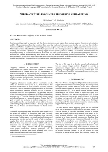
The International Archives of the Photogrammetry, Remote Sensing and Spatial Information Sciences, Volume XLII-3/W3, 2017Frontiers in Spectral imaging and 3D Technologies for Geospatial Solutions, 25–27 October 2017, Jyväskylä, Finlandaddition, only the range of the Arduino radio signal limits thedistance between cameras.The wireless system was implemented by applying a radiotransmitter/receiver pair for each camera or camera group that istriggered using one of the Arduino data pins. Our prototype hasan option to use either a 315MHz frequency or a 434MHzfrequency. In addition, a dual frequency operation is alsopossible. This alternative is useful if there are two cameraclusters that take images with different frequencies, but stillsynchronously. Our current wireless prototype version triggersthe camera almost directly from the signal pin of the receiverwith only minor analog filtering. However, some filtering isneeded to separate the signal from background noise, especiallyin noisy conditions, when there is other traffic in the 315MHzor 434MHz bands. Because of this, we use a simple capacitorthat which filters most of the noise from the radio signal.The principle of using a capacitor to filter the noise is that whenthe signal output pin of the RF receiver outputs a voltage, it ischarging a capacitor. The capacitor is connected between thesignal output pin and the ground pin of the RF receiver. Whenthe capacitor has been charged enough, it will trigger thecamera. If the signal includes only noise, it will take a relativelylong time to charge the capacitor. If the capacitor is sizedcorrectly, the cumulative noise between the image acquisitionsis not strong enough to charge the capacitor, and thus thecamera will not trigger inadvertently. Such a simple analogapproach introduces only very small latency to thesynchronization signal, which is important. There are no digitalprocessors in the signal path from an Arduino data pin to thecamera trigger port, which assumably leads to goodsynchronization accuracy.3. TRIGGERING SYSTEM SETUPSThe simplest form of our triggering prototype is the wiredArduino trigger unit as shown in Figure 1. The system consistsof only an Arduino Uno microcontroller board and two wires.One wire is the trigger ground and the other wire is the triggersignal. The signal cable can be attached to any of the ArduinoUno 14 data pins. The data pins can be configured to act asoutputs or inputs. In all our examples, we configure data pins asoutputs. Arduino Uno can be powered from a USB input or byan external power supply with a voltage range of 6V to 20V.The recommended voltage range is 7V to 12V.For wireless triggering, we use an Arduino data pin to operate aWRL-10535 Radio Frequency (RF) transmitter, which sendsthe trigger signal by an analog radio transmission to the WRL10533 RF receiver. The transmitter is powered from the 5Voutput of the Arduino Uno board, as shown in Figure 2 (the redwire). It is recommended to supply at least 7V to the Uno boardto make sure the 5V output from the board is stable. The yellowwire is the trigger signal and the white wire is the ground.Figure 2. The Arduino Uno wireless trigger setup. The red wireis a 5V voltage wire that powers the RF transmitter, the whitewire is for the ground, and the yellow wire gets the triggersignal from the Uno data output pin.Figure 3 shows two WRL-10533 RF receivers. They receive thesignal sent by the WRL-10535 transmitter, and the data pin canbe used to trigger the camera. We recommend using a film boxpolyester capacitor to filter the receiver data pin noise as shownin Figure 3. Figure 4 shows the simple capacitor filter weapplied to reduce noise of the RF receiver data output pin. Theuse of the filter capacitor is discussed in more detail in theDiscussion chapter.Figure 3. Two RF receivers with 0.068 μF filter capacitors.Receivers are powered by a 5V voltage source via red wires.White wires are for the ground and yellow wires are the cameratrigger wires.Figure 1. The Arduino Uno microcontroller setup for wiredcamera triggering. The black wire goes to the ground pin, andthe yellow wire gives the trigger signal from the Arduino Unodata output pin.Figure 4. The schematic of the RF receiver filter capacitor.A dual frequency operation using two different frequencytransmitter/receiver pairs was also tested. Figure 5 shows theThis contribution has been es-XLII-3-W3-101-2017 Authors 2017. CC BY 4.0 License.102
The International Archives of the Photogrammetry, Remote Sensing and Spatial Information Sciences, Volume XLII-3/W3, 2017Frontiers in Spectral imaging and 3D Technologies for Geospatial Solutions, 25–27 October 2017, Jyväskylä, Finlanddual frequency transmitter setup. Note that in this case, theyellow signal wire is split to both the transmitters, but two dataoutput pins can be used if two differently timed trigger signalsare desired.rotation plane were closely the same. The rotation speed isdependent on how much voltage is selected. We utilized anadjustable external power source that was set to 14.4 V. In ourcase, this corresponded to 104 rotations per second (6240RPM), which was measured with a Turnigy Tachometer. Inother words, the difference of one degree equals to a 26.71microseconds time difference.In this experiment, two identical industrial cameras wereutilized. Point Grey’s GigE global shutter cameras BFLY-PGE50S5C-C with Fujinon HF-818-12M lenses were set to capturefull 2448 x 2048 color images. To capture the moving pointerwith a minimum blur, the shortest 0.022 ms exposure time wasapplied. In Figure 7, an example of simultaneously capturedimages is presented.Figure 5. Dual frequency wireless setup using 315MHz and434MHz transmitters.4. TRIGGER DETECTIONIn order to measure triggering delay between cameras, aprototype of a rotating trigger detection system (namedRoTriDeS) was developed (Figure 6). The system utilizes amodified cooling fan. A clock pointer was attached to the fanmotor housing. To assist automatic measurements, three redtargets were placed in the system. One target is at the rotationcenter of the system, the second target is on the moving end ofthe pointer, and the third target is assembled onto the frame,which is not moving.Figure 6. The rotating trigger detection system for two cameras.Cameras were mounted in such a way that the image planeswere close to parallel to the rotation plane of the pointer. Inaddition, the perpendicular distance from both cameras to theFigure 7. An example of simultaneously captured images withtwo triggered cameras.The center points of the red targets were measuredautomatically. However, finding the seed points of the targetswas the first step. The rotation center and the static target on theframe needed manually pointed initial locations as seed points,but the moving target required a more advanced system. First ofall, a limited search space was manually selected. Then, thepurest red pixel was searched and considered as a seed point.In the next step, the center points of targets were computed. Forthis, a region growing algorithm was utilized starting from theseed points. Because the target plane and both image planeswere close to parallel, it was assumed that the effect of thetarget eccentricity due to the projective geometry (Luhmann,2014) can be neglected. Also, a possible effect of chromaticaberration of color bands (Cronk et al., 2006) was neglected. Inpractice, the region growing algorithm utilized only red andgreen bands. Because the lighting conditions were not changingduring the image acquisition, simple thresholds for regiongrowing were set empirically. These thresholds included theminimum acceptable value for red color and another thresholdfor the ratio of red and green bands. In order to prevent possibledivision by zero, both color values were increased by one. Asimple centroid was computed from the pixels belonging to atarget. This method has been reported to give a good sub-pixelaccuracy (Shortis et al., 1995).Two lines were computed for each image to reveal the angle ofthe pointer (Figure 8). The first line passes through the rotationcenter of the pointer and the moving point target of the pointer.The second line goes through the rotation center of the pointerand the static target on the frame. The angle between these twolines was computed and compared with the corresponding anglefrom another image. Such angular differences were convertedinto microseconds describing the triggering delay betweencameras.This contribution has been es-XLII-3-W3-101-2017 Authors 2017. CC BY 4.0 License.103
The International Archives of the Photogrammetry, Remote Sensing and Spatial Information Sciences, Volume XLII-3/W3, 2017Frontiers in Spectral imaging and 3D Technologies for Geospatial Solutions, 25–27 October 2017, Jyväskylä, FinlandFigure 8. The angles between found lines were measured andcompared between images from two different cameras. In thiscase, the angle difference was 0.287 degrees, which indicates a7.7 μs triggering difference.transmitter and receiver was 10 m, and there was a mineralwool insulated drywall between the RF transmitter and two RFreceivers. Figure 11 shows the trigger signals measured with adigital DS1M12 oscilloscope from the RF receiver data outputpins after the capacitor filter. The graph shows strong noisebefore the RF transmission starts, but as soon as the transmitterstarts to transmit, the signal becomes clear and shows very lownoise levels and good synchronization accuracy. Most industrialcameras can be set to trigger from a rising or falling edge. Oursignal uses an equal time for the “high” and “low” states, thusresulting in the same frequency for the image capture regardlessof whether the camera triggers on the rising or falling edge ofthe signal.5. RESULTSAs the reference, the results of the old LPT-based wiredtriggering system were included in the examination. Thetriggering time differences between cameras in the wiredsystem are illustrated in images 9 and 10. In all experiments,100 images with both cameras were taken with the samesettings.Figure 11. An oscilloscope measurement series of the two RFreceiver data output pins.Figures 12 to 15 illustrate the triggering time differences in thewireless triggering systems. The main results are collected inTable 1, which presents the mean, standard deviation,minimum, and maximum values of the triggering timedifferences. Again, each test case included 100 samples.Figure 9. Triggering differences for 100 samples (blue line) anda trend line (red line).Figure 12. Triggering differences for 100 samples (blue line)and a trend line (red line).Figure 10. Triggering differences for 100 samples (blue line)and a trend line (red line).The behavior of noise in the case of wireless triggering wasexamined separately in a normal household environment, whichincluded typical radio noise such as cell phones, radios, and WiFi base stations. During this test, the distance between wirelessFigure 13. Triggering differences for 100 samples (blue line)and a trend line (red line).This contribution has been es-XLII-3-W3-101-2017 Authors 2017. CC BY 4.0 License.104
The International Archives of the Photogrammetry, Remote Sensing and Spatial Information Sciences, Volume XLII-3/W3, 2017Frontiers in Spectral imaging and 3D Technologies for Geospatial Solutions, 25–27 October 2017, Jyväskylä, FinlandArduino to use more complex functions by using a so-calledhandshake trigger signal pattern that would then be received byanother Arduino microcontroller attached to the radio receiver.The receiving Arduino board would then use one of the datapins to trigger the camera via a wired signal. However, thisvision was not implemented in this research.Figure 14. Triggering differences for 100 samples (blue line)and a trend line (red line).Because of the analog nature of our prototype, we are limited tousing only certain intervals of camera triggering. If we pausefor too long between the trigger signals, the camera willeventually start to trigger by the noise when the capacitor isfully charged. Our current prototype uses only a capacitorfiltering of noise, but a low-pass filter, for example, can beconsidered to achieve better results. The so-called RC filter is agood example of such a low-pass filter, and it only needs anadditional resistor between the capacitor and the signal outputpin of the RF receiver. Our prototype uses a polyester film boxcapacitor, which is sized by empirical testing.The rotating trigger detection system is feasible only for globalshutter cameras. In the case of rolling shutter cameras, thepointer bends in the images because of different exposuresynchronization within an image frame (see Figure 16). The useof such cameras would require a rolling shutter correction (e.g.,Grundmann et al., 2012; Ito and Okatani, 2016). However, evenwith such a correction, it is expected that the accuracy is notequal to global shutter cameras. In our case, the main objectivewas to evaluate the triggering system, and therefore we did notfocus on implementing a rolling shutter correction but insteadused easier global shutter cameras.Figure 15. Triggering differences for 100 samples (blue line)and a trend line (red line).Table 1. Statistics for all experiments. The number of sampleswas 100 in each case.STDminmaxMean(μs)(μs)(μs)(μs)Wired, old system9.106.110.1526.42Wired, Arduino8.916.100,0129.31Wireless, 315 MHz, 0.10.077.925.5224.33μFWireless, 315 MHz,8.016.080.1625.410.068 μFWireless, 424 MHz,8.726.090.0227.080.068 μFWireless, dual, 315 and29.289.427.100.32424 MHz, 0.068 μF6. DISCUSSIONBecause of noise, our approach might lead to malfunctions ifthe filtering capacitor is saturated by the noise. The sources ofnoise include the noise of the RF transmitter, the noise of theRF receiver, and the RF noise of the operating environment.Especially the RF noise of the environment can be very high inmany situations since both 315MHz and 434MHz bands arewidely used by many communication devices, such as remotecar keys. The results in Figure 11, however, show that innormal cases no extra triggers occur in normal conditions. Ifdisturbing signals become an issue, it is possible to program theFigure 16. The behavior of a rolling shutter camera in the caseof a rotating target. Because the view is scanned vertically withthis camera, an almost horizontal moving pointer looksrelatively straight (left image), whereas a moving verticalpointer bends strongly (right image).The results include camera-based triggering errors, which canvary. Therefore, it is not obvious how much of the error istrigger-based and how much is camera-based. Minimum andmaximum trigger time differences (see Table 1) should beinterpreted cautiously. However, we believe it is safe to say thatusing a wireless triggering system with two differentfrequencies introduces additional trigger-based synchronizationvariation. This might be due to cross-talk between receivers ofdifferent frequencies. Interestingly, other wireless setups haveslightly smaller mean trigger differences than wired systems. Inaddition, systematic errors can be corrected from the cameraside by adding a short delay to the camera that triggers first,further improving the results.Our trigger system can be extended to cover other commercialcameras and other electronic devices because the ArduinoThis contribution has been es-XLII-3-W3-101-2017 Authors 2017. CC BY 4.0 License.105
The International Archives of the Photogrammetry, Remote Sensing and Spatial Information Sciences, Volume XLII-3/W3, 2017Frontiers in Spectral imaging and 3D Technologies for Geospatial Solutions, 25–27 October 2017, Jyväskylä, Finlandoffers a very flexible but straightforward way to implementvarious triggering scenarios and can be further extended toinclude other functions such as a serial data connection throughradio transmitter/receiver pairs used to trigger auxiliary devices.Even if industrial cameras can be triggered directly from anArduino data pin, for wired triggering of commercial camerasan additional transistor is needed, unfortunately. However, anArduino data pin can be utilized to saturate the transistor, whichin turn shorts the camera trigger pin to ground. Certain cameramanufacturers also offer functions such as focus and zoomcontrol, and some cameras need a certain type of wake-fromsleep signal in order to accept remote triggering at all. Arduinoplatforms can be programmed to cope with all such differentsituations. Our prototype uses a one-direction operation, but itcould be extended to cope with bi-directional communicationby adding an Arduino controller to the receiver side as well.One example of such operation would be to read the timestampof the camera trigger and send it back to the Arduino controllerto make sure the synchronization was correct in all cameras.7. CONCLUSIONSIto, E., Okatani, T., 2016. Self-calibration-based Approach toCritical Motion Sequences of Rolling-shutter Structure fromMotion. CoRR, abs/1611.05476, 9 pages.Litos, G., Zabulis, X., Triantafyllidis, G., 2006. SynchronousImage Acquisition based on Network Synchronization. In:Proceedings of the 2006 Conference on Computer Vision andPattern Recognition Workshop (CVPRW’06), 6 pages.Luhmann T., 2014. Eccentricity in Images of Circular andSpherical Targets and its Impact to 3D Object Reconstruction.International Archives of the Photogrammetry, Remote Sensingand Spatial Information Sciences, vol. xl-5, pp. 363-370.Shortis, M. R., Clarke, T. A., Robson, S., 1995. PracticalTesting of the Precision and Accuracy of Target ImageCentring Algorithms. Videometrics IV, SPIE Vol. 2598, pp. 6576.Thiel, D., Goulart, M. G., Botelho, S. S. C., Bem, R. A., 2013.Hardware and Software Infrastructure to Image Acquisitionusing Multiple Cameras. In: Proceedings of SIBGRAPI 2013(XXVI Conference on Graphics, Patterns, and Images), pp. 1-6.Arduino appeared to be a flexible and efficient environment toimplement camera-triggering systems, and it is readilyextendable by various add-on modules developed by peoplefrom all around the world. Our aim was to make Arduino-basedwired and wireless triggering systems and to evaluate theirsynchronization accuracy. For evaluation purposes, a prototypeof a rotating trigger detection system (named RoTriDeS) wasdeveloped.The evaluation of triggering systems revealed that wirelesstriggering systems performed as well or even better than wiredsystems when only one frequency was applied for signaltransmission. However, when two different frequencies wereapplied, a small trigger-based delay was detectable.Overall, the triggering time differences were relatively small inall cases. The mean triggering differences varied between 7.92and 9.42 μs, and the maximum difference of all systems was29.31 μs. The maximum mean difference between systems was1.417 μs when the mean time difference values of the differentcases were compared. This research indicated that Arduinobased triggering systems are feasible and can be implementedwire-based or wirelessly.8. ACKNOWLEDGEMENTSThis article was supported by the Academy of Finland, theCentre of Excellence in Laser Scanning Research, CoE-LaSR(No. 272195) and project “COMBAT” (293389). The FinnishFunding Agency for Innovation is acknowledged for support inproject “VARPU” (7031/31/2016).9. REFERENCESCronk, S., Fraser, C.S., Hanley, H.B., 2006. Automaticcalibration of colour digital cameras. Photogrammetric Record,21 (116), pp. 355-372.Grundmann, M., Kwatra, V., D. Castro, D., 2012. Calibrationfree rolling shutter removal. In: Proc. ICCP, 2012, 8 pages.This contribution has been es-XLII-3-W3-101-2017 Authors 2017. CC BY 4.0 License.106
WIRED AND WIRELESS CAMERA TRIGGERING WITH ARDUINO H. Kauhanen a, *, P. Rönnholm a a Aalto University, School of Engineering, Department of Built Environment, P.O. Box 14100, 00076 AALTO, Finland (heikki.kauhanen, petri.ronnholm)@aalto.fi Commission Ι, WG I/5 KEY WORDS: Camera, Triggering, Wired, W