Transcription
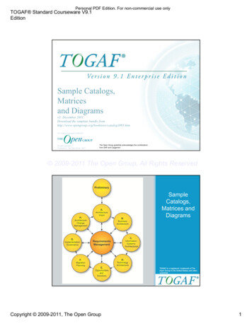
UML Tutorial for C - Windows PlatformGDPro 5.0Chapter 4: Use Case DiagramThe Use Case DiagramWhat is a Use Case Diagram Describes the behavior of a system from a user’s standpoint Functional description of a system and its major processes Provides a graphic description of who will use a system and what kinds of interactions to expectwithin that system Processes that occur within the application area are called use cases Entities outside the area that are going to use the application are called actorsWhen to use a Use Case DiagramWhen describing requirements for a system in the analysis, design, implementation and documentationstages.When Constructing Use Cases Think About What tasks the actor must perform What resources the actor requires in terms of data read/written Keeping the use cases simpleCreating the System's Use Case DiagramUsing the Use Case Diagram model, you show the relationship among actors and use cases within asystem. The Use Case diagram we will be creating tracks various functions and those who interact withthe functions within a banking system.Drawing Use Case symbolsUse Case symbols define instances. When representing an instance, you:Draw use case symbolsName the symbolsDraw the actor symbolsLabel the actor symbolsLink use case and actor symbols with communications and extendsAfter you have completed the step-by-step procedure outlined in the tutorial, your use case diagramshould look similar to the following example.-1 2000 Advanced Software Technologies, Inc.
UML Tutorial for C - Windows PlatformGDPro 5.0Note: The diagram shown above is for reference only. Use the instructions beginning on the nextpage to draw your Use Case diagram.The Use Case Diagram PaletteEach icon on this palette represents a notation used to create a use case diagram.IconNotationActorDefinitionAn actor represents a coherent set of rolesthat users of a system play when interactingwith the use cases of the system.Actors can be anything - humans, devices,other systemsOne physical object can play several roles andso can be modeled by several actors.-2 2000 Advanced Software Technologies, Inc.
UML Tutorial for C - Windows PlatformGDPro 5.0Use CaseUse cases describe what a system does, not how itdoes it. A use case contains multiple scenarios,each of which describes a specific flow of eventsthrough the use case. Use case behavior isspecified by describing the scenarios clearlyenough for outsiders to understand.PackageThe Package symbol is used in the Use Case,Class, and Component diagrams. A package is agrouping of model elements. Packages themselvesmay be nested within other packages. A packagemay contain both subordinate packages andordinary model elements. Some packages may beSubsystems of Models. The entire systemdescription can be thought of as a single high-levelsubsystem package with everything else in it.Design PatternPatterns describe small, recurring entities,reusable on a day to day basis in order toresolve specific problems. These patterns do notexpress the general form of an application.This symbol is available in the followingdiagrams: Use Case, Class, Collaboration,Deployment, and Component.GeneralizationLinkGeneralization is the taxonomic relationshipbetween a more general element and a morespecific element that is fully consistent with thefirst element and that adds additionalinformation. This link is also known as aspecialization or inheritance link.Note: In previous version there was a Use CaseLink and an Actor Link. The Generalization linktakes the place of both of this icons.DependencyLinkThe dependency link is a semantic relationbetween the source and target elements. Itindicates that when there is a change to thetarget element there may be a changenecessary to the source element. You can labelthe dependency link and set the stereotype.Comm LinkThe link is used to associate an actor to a usecase. It shows participation of an actor in a usecase and is the only relationship between actorsand use cases.PatternMember LinkUsed to show the member classes or objectsparticipating in a pattern.-3 2000 Advanced Software Technologies, Inc.
UML Tutorial for C - Windows PlatformBinaryConstraintGDPro 5.0The binary constraint notation is available on alldiagram palettes. A constraint is a semanticrelationship among model elements thatspecifies conditions and propositions that mustbe maintained as true. Otherwise the systemdescribed by the model is invalid. Certain kindsof constraints (such as association "or"constraint) are predefined in UML; others can beuser defined. A constraint represents semanticinformation attached to a model element, not justa view of it.A binary constraint allows a constraint to bedefined between any symbols on the diagram.The binary constraint allows the constraint to bedefined on the link rather than in a note symbol.If there is a need for a single constraint or threeor more way constraint, then a note symbol isused to explain the constraint and the notesymbol is linked to the constrained symbolsusing a note link.Note LinkThe note link notation is available on all diagrampalettes. The note pad can be used to recordinformation for a object or link in a diagram. Thisinformation is not included in generated code butis for information only. Each note pad cancontain unlimited text, can be numbered, astereotype defined, and a noted elemententered.Note PadThe note pad notation is available on all diagrampalettes. The note pad can be used to recordinformation for an symbol or link in a diagram.This information is not included in generatedcode but is for information only. Each note padcan contain unlimited text, and be numbered.You can also define a stereotype, and enter anoted element.Defining the Use CasesThe first step is to define the use cases within the system.1.Clickon the Use Case Diagram palette to select it.2.Place the cursor in the upper middle portion of the design area and click once. A Use Case symbolis placed in the design area.3.To change the name of a symbol or link, all you have to do is select the symbol or link and starttyping. A text box automatically opens. Enter the label "Withdraw Money" and click anywhereoutside the text box. The unnamed label is replaced with the new text.-4 2000 Advanced Software Technologies, Inc.
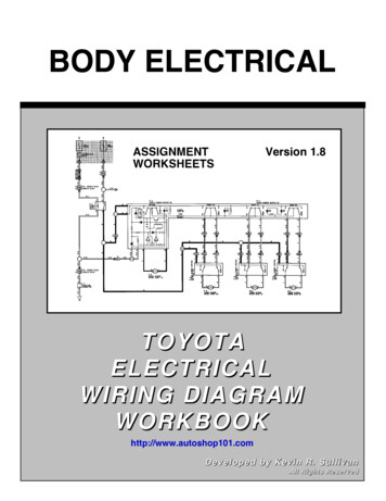
UML Tutorial for C - Windows Platform4.GDPro 5.0Double-click the Use Case icon in the Use Case Diagram Palette. The cursor changesindicating it is in the multiple placement mode. By double-clicking on the Use Case icon, you candraw multiple Use Case symbols in the design area.Note: You can also click the icon once and then while holding down the space bar, place multiplesymbols in the diagram. Release the space bar before placing the last symbol.5.Place six more use cases in the design area as illustrated.Note: As you place the symbols in the design area, notice that a representative symbol is placed inthe System Hierarchy Window under the system name. The list of symbols is organizedalphabetically according to the symbol label.6.Deselect the Use Case symbol icon by clicking the cursor iconDiagram palette or press the ESC key.located above the Use CaseLabeling the Use Case Symbol1.Click once to select the use case that is to become the Withdraw Cash from ATM. Handles appeararound the class symbol.2.Double-click the use case and the Properties Editor dialog box opens. The cursor is active in theName text box and the label unnamed is highlighted.-5 2000 Advanced Software Technologies, Inc.
UML Tutorial for C - Windows PlatformGDPro 5.03.Enter the text "Withdraw Cash" and press Enter. The cursor advances to the next line.4.Enter the text "from ATM" and click. The text "Withdraw Cash from ATM" is entered inthe use case symbol and the dialog box closes.Label Remaining Use CasesWe will use the direct entry method to label the remaining class symbols.1.Click once to select the symbol to be labeled "Deposit Money".2.Enter the text "Deposit Money" and click anywhere outside the text box. The symbol is labeled.3.Repeat steps 1 and 2 to label the remaining use case symbols.-6 2000 Advanced Software Technologies, Inc.
UML Tutorial for C - Windows PlatformGDPro 5.0Add ActorsThe next step in creating a Use Case diagram is to place and define the actors. An actor is a predefinedstereotype of type showing an entity outside the package that interacts with use case symbols.1.Select the Actor icon by clicking once on thein the Use Case palette.2.Put the actor in the diagram by placing the cursor to the left of the Use Case symbols and clickingonce. An unnamed actor is placed in the design area.-7 2000 Advanced Software Technologies, Inc.
UML Tutorial for C - Windows Platform3.GDPro 5.0Double-click the actor graphic and the Properties Editor for Actor dialog box opens.-8 2000 Advanced Software Technologies, Inc.
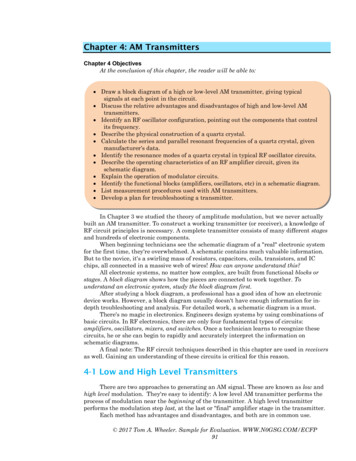
UML Tutorial for C - Windows Platform4.GDPro 5.0Enter the text "Customer" in the Name text box and clickthe actor is labeled. The dialog box closes andContinue Adding Actors1.Double-click the Actor icon in the Use Case Diagram Paletteicon is grayed out.to place multiple symbols. The2.Place four more actors in the design area as illustrated.3.Deselect the Actor icon by clicking the cursor iconpress the ESC key.4.Click once on the actor symbol that will be labeled Bank Teller. The actor is selected.5.Click the unnamed label under the selected actor and the Name pop-up editor opens.located by the Use Case Diagram palette or-9 2000 Advanced Software Technologies, Inc.
UML Tutorial for C - Windows PlatformGDPro 5.06.Enter the text "Bank Teller" in the text box and press Enter. The pop-up editor closes and the actorsymbol is labeled.7.Repeat steps 4 through 6 to label the remaining actors Bank Computer, Technician and Loan Officer.Linking Actors to ActorsThe actor link shows the communication or connection between an actor and another actor. BecauseORTHOGONAL LINKS is the default setting, all links drawn are automatically squared.1.Click the Generalization Link icon in the Use Case Diagram palette.2.Click inside the actor symbol labeled Bank Teller, drag the cursor down to the actor labeled BankComputer and click again. A valid link snaps in place between the two actors.Key: You can define the proximity snap sensitivity of establishing link relationships. When youdraw a link to a symbol, the link is automatically connected when it is dropped within a userdefined distance from the target symbol.3.Double-click the generalization link and the Properties Editor for Generalization Link dialog boxopens.4.Select "implementation" from the Stereotype drop down list and clickcloses and the link is labeled " implementation ". The dialog box-10 2000 Advanced Software Technologies, Inc.
UML Tutorial for C - Windows PlatformGDPro 5.0Linking Actors to Use CasesA link shows the communication or connection between an actor and a use case class.1.Click the CommLink icon in the Use Case Diagram palette.2.Click inside the actor symbol labeled Customer, drag the cursor inside the "Withdraw Cash FromATM" use case symbol and click again. A link snaps in place from the actor to the use case.Note: You can draw the link directly from the "Customer" actor to the "Withdraw Cash From ATM"use case. The link is automatically squared as shown in the following graphic.3.Label the link by double-clicking the commlink symbol between Customer and Withdraw Cash fromATM. The Properties Editor for Comm Link dialog box opens.4.Enter the text "uses" and click. The dialog box closes and the commlink is labeled.-11 2000 Advanced Software Technologies, Inc.
UML Tutorial for C - Windows PlatformGDPro 5.0Draw Remaining Links1.Click the CommLink icon in the Use Case palette2.While holding down the space bar, connect the following actors and use cases by clicking first in theactor symbol, dragging the cursor to the use case symbol and then clicking once again.3.ACTORUSE CASECustomerDeposit Cash at ATMCustomerApply for LoanBank TellerWithdraw MoneyBank TellerDeposit MoneyBank ComputerWithdraw Cash From ATMBank ComputerDeposit Cash at ATMTechnicianService ATM'sRelease the space bar and draw the last link.Loan OfficerProcess a LoanUsing the Extended LinksAn extended link shows a relationship from one use case to another, specifying how the behavior definedfor the first use case can be inserted into the behavior defined for the second use case.1.Click the Generalization Link icon in the Use Case diagram palette.2.Click once in the "Withdraw Cash From ATM" symbol, drag the cursor to the "Withdraw Money"symbol and click again. A Use Case link is drawn with the arrow pointing towards the WithdrawMoney symbol.-12 2000 Advanced Software Technologies, Inc.
UML Tutorial for C - Windows Platform3.GDPro 5.0Repeat steps 1 and 2 to draw extend links between the following use cases:Deposit Cash at ATM -- Deposit MoneyProcess a Loan -- Apply for LoanAdding the Package SymbolA package is a collection of connected units that are organized to accomplish a specific purpose. For thistutorial the package encompasses all the use cases needed for the specified "banking" purpose.1.Click the Package iconin the Use Case Diagram palette.2.Starting in the upper left corner of the diagram, click and drag the cursor to the lower right corner andrelease the mouse. A package labeled unnamed is drawn around the use case symbols. Do notinclude the actors in the package.Key: Once you place a package around the use case symbols, these symbols are now in arelationship with the package. When you select a use case symbol in the package, thesymbol now has blue "handles" instead of black.Note: Notice that once the package is drawn, a package symbol icon appears in the SystemHierarchy Window and all the uses cases are placed below that package icon.-13 2000 Advanced Software Technologies, Inc.
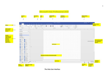
UML Tutorial for C - Windows PlatformGDPro 5.03.Double-click in the background of the package. A Properties Editor for Package dialog box opens.4.Enter the text "Banking" in the Name text box.5.Tab to advance to the Tab text box and enter the number "1". Clickdialog box and the package tab and label appear in the Package box.in the propertiesThe Finished Use Case DiagramOnce you have added the package and labeled it, your finished diagram should resemble the following:-14 2000 Advanced Software Technologies, Inc.
UML Tutorial for C - Windows PlatformGDPro 5.0-15 2000 Advanced Software Technologies, Inc.
draw a link to a symbol, the link is automatically connected when it is dropped within a user-defined distance from the target symbol. 3. Double-click the generalization link and the Properties Editor for Generalization Link dialog box opens. 4. Select "implementation" from