Transcription
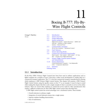
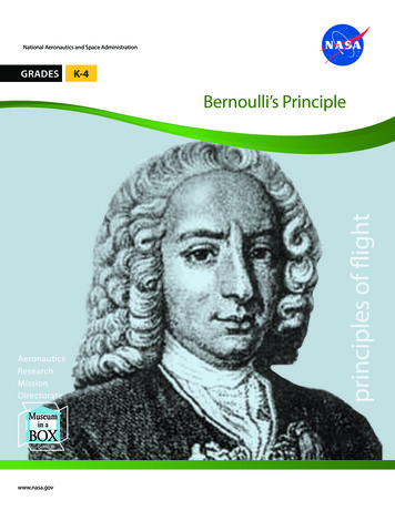
From the Library at www.OnlineGroundSchool.comChapter 6Flight ControlsIntroductionThis chapter focuses on the flight control systems a pilot usesto control the forces of flight and the aircraft’s direction andattitude. It should be noted that flight control systems andcharacteristics can vary greatly depending on the type ofaircraft flown. The most basic flight control system designsare mechanical and date back to early aircraft. They operatewith a collection of mechanical parts, such as rods, cables,pulleys, and sometimes chains to transmit the forces of theflight deck controls to the control surfaces. Mechanical flightcontrol systems are still used today in small general andsport category aircraft where the aerodynamic forces are notexcessive. [Figure 6-1]6-1
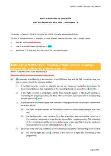
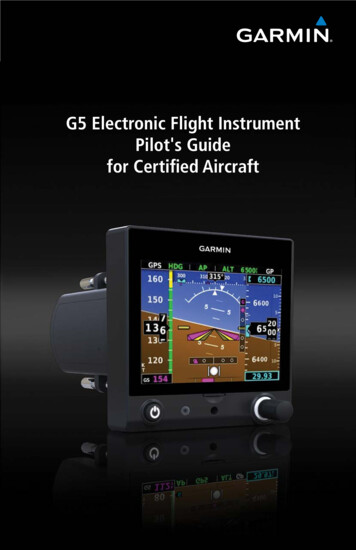
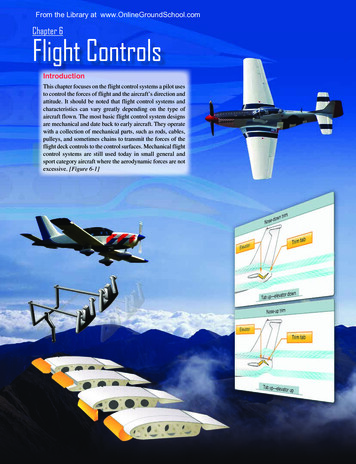
of this project is to develop an adaptive neural network-basedflight control system. Applied directly to flight control systemfeedback errors, IFCS provides adjustments to improveaircraft performance in normal flight, as well as with systemfailures. With IFCS, a pilot is able to maintain control andsafely land an aircraft that has suffered a failure to a controlsurface or damage to the airframe. It also improves missioncapability, increases the reliability and safety of flight, andeases the pilot workload.Control stickElevatorPulleysPush rodFigure 6-1. Mechanical flight control system.As aviation matured and aircraft designers learned more aboutaerodynamics, the industry produced larger and faster aircraft.Therefore, the aerodynamic forces acting upon the controlsurfaces increased exponentially. To make the control forcerequired by pilots manageable, aircraft engineers designedmore complex systems. At first, hydromechanical designs,consisting of a mechanical circuit and a hydraulic circuit,were used to reduce the complexity, weight, and limitationsof mechanical flight controls systems. [Figure 6-2]As aircraft became more sophisticated, the control surfaceswere actuated by electric motors, digital computers, or fiberoptic cables. Called “fly-by-wire,” this flight control systemreplaces the physical connection between pilot controls andthe flight control surfaces with an electrical interface. Inaddition, in some large and fast aircraft, controls are boostedby hydraulically or electrically actuated systems. In boththe fly-by-wire and boosted controls, the feel of the controlreaction is fed back to the pilot by simulated means.Current research at the National Aeronautics and SpaceAdministration (NASA) Dryden Flight Research Centerinvolves Intelligent Flight Control Systems (IFCS). The goalToday’s aircraft employ a variety of flight control systems.For example, some aircraft in the sport pilot category rely onweight-shift control to fly while balloons use a standard burntechnique. Helicopters utilize a cyclic to tilt the rotor in thedesired direction along with a collective to manipulate rotorpitch and anti-torque pedals to control yaw. [Figure 6-3]For additional information on flight control systems, referto the appropriate handbook for information related to theflight control systems and characteristics of specific typesof aircraft.Flight Control SystemsFlight ControlsAircraft flight control systems consist of primary andsecondary systems. The ailerons, elevator (or stabilator),and rudder constitute the primary control system and arerequired to control an aircraft safely during flight. Wing flaps,leading edge devices, spoilers, and trim systems constitutethe secondary control system and improve the performancecharacteristics of the airplane or relieve the pilot of excessivecontrol forces.Primary Flight ControlsAircraft control systems are carefully designed to provideadequate responsiveness to control inputs while allowing aYawNeutralCyclic stickLEGENDcControl stick (AFT—nose up)CycliCableCycliveCollecticHydraulic pressureHydraulic returnPivot pointElevator (UP)YawControl valvesControl cablesCyclicclicCyeectivCollNeutralPower disconnect linkageNeutralPower cylinderFigure 6-2. Hydromechanical flight control system.6-2Anti-torque pedalsCollective leverFigure 6-3. Helicopter flight control system.
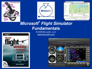
natural feel. At low airspeeds, the controls usually feel softand sluggish, and the aircraft responds slowly to controlapplications. At higher airspeeds, the controls becomeincreasingly firm and aircraft response is more rapid.Movement of any of the three primary flight control surfaces(ailerons, elevator or stabilator, or rudder), changes theairflow and pressure distribution over and around the airfoil.These changes affect the lift and drag produced by the airfoil/control surface combination, and allow a pilot to control theaircraft about its three axes of rotation.Design features limit the amount of deflection of flightcontrol surfaces. For example, control-stop mechanisms maybe incorporated into the flight control linkages, or movementof the control column and/or rudder pedals may be limited.The purpose of these design limits is to prevent the pilot frominadvertently overcontrolling and overstressing the aircraftduring normal maneuvers.A properly designed aircraft is stable and easily controlledduring normal maneuvering. Control surface inputs causemovement about the three axes of rotation. The types ofstability an aircraft exhibits also relate to the three axes ofrotation. [Figure 6-4]ElevRudder—YawatorLa—(lo tera Pitnlsta gi ax chbil tud isity ina) lVertical ng(lateralaxis ity)stabilAileronsAilerons control roll about the longitudinal axis. The aileronsare attached to the outboard trailing edge of each wing andmove in the opposite direction from each other. Ailerons areconnected by cables, bellcranks, pulleys, and/or push-pulltubes to a control wheel or control stick.Moving the control wheel, or control stick, to the rightcauses the right aileron to deflect upward and the left aileronto deflect downward. The upward deflection of the rightaileron decreases the camber resulting in decreased lift onthe right wing. The corresponding downward deflection ofthe left aileron increases the camber resulting in increasedlift on the left wing. Thus, the increased lift on the left wingand the decreased lift on the right wing causes the aircraftto roll to the right.Adverse YawSince the downward deflected aileron produces more lift asevidenced by the wing raising, it also produces more drag.This added drag causes the wing to slow down slightly.This results in the aircraft yawing toward the wing whichhad experienced an increase in lift (and drag). From thepilot’s perspective, the yaw is opposite the direction of thebank. The adverse yaw is a result of differential drag and theslight difference in the velocity of the left and right wings.[Figure 6-5]Adverse yaw becomes more pronounced at low airspeeds.At these slower airspeeds, aerodynamic pressure on controlsurfaces are low, and larger control inputs are required toLiftDragAirplaneMovementAxes ofRotationType lDirectionalFigure 6-4. Airplane controls, movement, axes of rotation, andAdvLiftPrimaryControlSurfacegDrae r s e yawFigure 6-5. Adverse yaw is caused by higher drag on the outsidewing that is producing more lift.type of stability.6-3
effectively maneuver the aircraft. As a result, the increasein aileron deflection causes an increase in adverse yaw. Theyaw is especially evident in aircraft with long wing spans.Application of the rudder is used to counteract adverseyaw. The amount of rudder control required is greatest atlow airspeeds, high angles of attack, and with large ailerondeflections. Like all control surfaces at lower airspeeds,the vertical stabilizer/rudder becomes less effective andmagnifies the control problems associated with adverse yaw.All turns are coordinated by use of ailerons, rudder, andelevator. Applying aileron pressure is necessary to placethe aircraft in the desired angle of bank, while simultaneousapplication of rudder pressure is necessary to counteract theresultant adverse yaw. Additionally, because more lift isrequired during a turn than during straight-and-level flight,the angle of attack (AOA) must be increased by applyingelevator back pressure. The steeper the turn, the more elevatorback pressure that is needed.As the desired angle of bank is established, aileron andrudder pressures should be relaxed. This stops the angle ofbank from increasing, because the aileron and rudder controlsurfaces are in a neutral and streamlined position. Elevatorback pressure should be held constant to maintain altitude.The roll-out from a turn is similar to the roll-in, except theflight controls are applied in the opposite direction. Theaileron and rudder are applied in the direction of the roll-outor toward the high wing. As the angle of bank decreases,the elevator back pressure should be relaxed as necessaryto maintain altitude.Aileron deflected upDifferential aileronAileron deflected downFigure 6-6. Differential ailerons.the drag created by the lowered aileron on the opposite wingand reduces adverse yaw. [Figure 6-7]The frise-type aileron also forms a slot so air flows smoothlyover the lowered aileron, making it more effective at highangles of attack. Frise-type ailerons may also be designedto function differentially. Like the differential aileron, thefrise-type aileron does not eliminate adverse yaw entirely.Coordinated rudder application is still needed when aileronsare applied.Coupled Ailerons and RudderCoupled ailerons and rudder are linked controls. This isaccomplished with rudder-aileron interconnect springs, whichhelp correct for aileron drag by automatically deflectingthe rudder at the same time the ailerons are deflected. ForNeutralIn an attempt to reduce the effects of adverse yaw,manufacturers have engineered four systems: differentialailerons, frise-type ailerons, coupled ailerons and rudder,and flaperons.Differential AileronsWith differential ailerons, one aileron is raised a greaterdistance than the other aileron and is lowered for a givenmovement of the control wheel or control stick. This producesan increase in drag on the descending wing. The greater dragresults from deflecting the up aileron on the descending wingto a greater angle than the down aileron on the rising wing.While adverse yaw is reduced, it is not eliminated completely.[Figure 6-6]Frise-Type AileronsWith a frise-type aileron, when pressure is applied to thecontrol wheel, or control stick, the aileron that is being raisedpivots on an offset hinge. This projects the leading edge ofthe aileron into the airflow and creates drag. It helps equalize6-4RaisedDragLoweredFigure ailerons.5-4. Frise-type ailerons.Figure 6-7. Frise-type
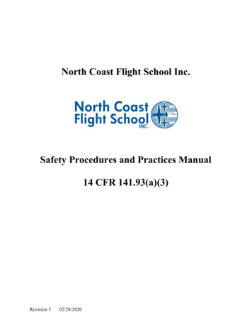
example, when the control wheel, or control stick, is movedto produce a left roll, the interconnect cable and spring pullsforward on the left rudder pedal just enough to prevent thenose of the aircraft from yawing to the right. The force appliedto the rudder by the springs can be overridden if it becomesnecessary to slip the aircraft. [Figure 6-8]FlaperonsFlaperons combine both aspects of flaps and ailerons. Inaddition to controlling the bank angle of an aircraft likeconventional ailerons, flaperons can be lowered togetherto function much the same as a dedicated set of flaps. Thepilot retains separate controls for ailerons and flaps. A mixeris used to combine the separate pilot inputs into this singleset of control surfaces called flaperons. Many designs thatincorporate flaperons mount the control surfaces away fromthe wing to provide undisturbed airflow at high angles ofattack and/or low airspeeds. [Figure 6-9]ElevatorThe elevator controls pitch about the lateral axis. Like theailerons on small aircraft, the elevator is connected to thecontrol column in the flight deck by a series of mechanicalRudder deflects with aileronsFigure 6-9. Flaperons on a Skystar Kitfox MK 7.linkages. Aft movement of the control column deflectsthe trailing edge of the elevator surface up. This is usuallyreferred to as the up-elevator position. [Figure 6-10]The up-elevator position decreases the camber of the elevatorand creates a downward aerodynamic force, which is greaterthan the normal tail-down force that exists in straight-and level flight. The overall effect causes the tail of the aircraftto move down and the nose to pitch up. The pitching momentoccurs about the center of gravity (CG). The strength of thepitching moment is determined by the distance betweenthe CG and the horizontal tail surface, as well as by theaerodynamic effectiveness of the horizontal tail surface.Moving the control column forward has the opposite effect.In this case, elevator camber increases, creating more lift(less tail-down force) on the horizontal stabilizer/elevator.This moves the tail upward and pitches the nose down. Again,the pitching moment occurs about the CG.Control columnaftUp elevatorNose upCGTail downAs mentioned earlier, stability, power, thrustline, and theposition of the horizontal tail surfaces on the empennageare factors in elevator effectiveness controlling pitch. ForDownwardaerodynamic forceRudder/Aileron interconnecting springsFigure 6-8. Coupled ailerons and rudder.Figure 6-10. The elevator is the primary control for changing thepitch attitude of an aircraft.6-5
example, the horizontal tail surfaces may be attached nearthe lower part of the vertical stabilizer, at the midpoint, orat the high point, as in the T-tail design.T-TailIn a T-tail configuration, the elevator is above most of theeffects of downwash from the propeller, as well as airflowaround the fuselage and/or wings during normal flightconditions. Operation of the elevators in this undisturbed airallows control movements that are consistent throughout mostflight regimes. T-tail designs have become popular on manylight and large aircraft, especially those with aft fuselagemounted engines because the T-tail configuration rem
of mechanical flight controls systems. [Figure 6-2] As aircraft became more sophisticated, the control surfaces were actuated by electric motors, digital computers, or fiber optic cables. Called “fly-by-wire,” this flight control system replaces the physical connection between pilot controls and the flight control surfaces with an electrical interface. In addition, in some large and fast .