Transcription
AHRI Standard 260 (I-P)2017 Standard forSound Rating of DuctedAir Moving andConditioning Equipment
IMPORTANTSAFETY DISCLAIMERAHRI does not set safety standards and does not certify or guarantee the safety of any products, components orsystems designed, tested, rated, installed or operated in accordance with this standard/guideline. It is stronglyrecommended that products be designed, constructed, assembled, installed and operated in accordance withnationally recognized safety standards and code requirements appropriate for products covered by thisstandard/guideline.AHRI uses its best efforts to develop standards/guidelines employing state-of-the-art and accepted industrypractices. AHRI does not certify or guarantee that any tests conducted under its standards/guidelines will be nonhazardous or free from risk.Note:This standard supersedes ANSI/AHRI Standard 260 (I-P)-2012 and differs in the following ways: Sound power shall be determined following ANSI/AHRI Standard 230 procedures if Sound Intensityis used.Sound ratings can be predicted for untested fan operating points and unit sizes with certain restrictions.Price 10.00 (M) 20.00 (NM)Printed in U.S.A. Copyright 2017, by Air-Conditioning, Heating and Refrigeration InstituteRegistered United States Patent and Trademark Office
TABLE OF CONTENTSSECTIONPAGESection 1. Purpose. 1Section 2. Scope . 4Section 3. Definitions.4Section 4. Requirements for Acquiring Sound Data .6Section 5. Sound Level Calculations . 14Section 6. Equipment Sound Ratings. .16Section 7. Conformance Conditions . 19TABLESTable 1.Reproducibility in the Determination of Ducted Equipment SoundPower Levels .13FIGURESFigure 1. Typical Ducted Product Application .2Figure 2. Relationship Between Sound Components and Sound Sources .3Figure 3. Concept Reverberation Room Ducted Discharge Test Set-up .8Figure 4. Concept Sound Intensity Ducted Discharge Test Set-up.8Figure 5. Concept Reverberation Room Ducted Inlet Test Set-up.8Figure 6. Concept Sound Intensity Ducted Inlet Test Set-up .9Figure 7. Concept Reverberation Room Casing Radiated Test Set-up .9Figure 8. Concept Sound Intensity Casing Radiated Test Set-up .9Figure 9. Concept Reverberation Room Free Discharge (or Inlet) Combined with CasingRadiated Test Set-up .10Figure 10 Concept Sound Intensity Free Discharge (or Inlet) Combined with CasingRadiated Test Set-up .10Figure 11. Concept Reverberation Room Free Discharge (or Inlet) Set-up. .11Figure 12. Concept Sound Intensity Free Discharge (or Inlet) Test Set-up .11
TABLE OF CONTENTS (CONTINUED)APPENDICESAppendix A. References – Normative . 20Appendix B. References – Informative . 21Appendix C. Acoustic Test Elbow Correction (E2) - Normative .22Appendix D. Effects of Other Sources - Normative .24Appendix E. Supply Fan Modulation Device Effects - Normative .25TABLES FOR APPENDICESTable C1. Insertion Loss of Unlined Elbows.22Table C2. Examples of Test Elbow Insertion Loss, dB .23FIGURES FOR APPENDICESFigure C1. Insertion Loss of Unlined Acoustic Test Duct Elbows .22
AHRI STANDARD 260 (I-P)-2017SOUND RATING OF DUCTED AIR MOVING ANDCONDITIONING EQUIPMENTSection 1. Purpose1.1Purpose. The purpose of this standard is to establish for the indoor portions of factory-assembled ducted airmoving and conditioning equipment and not the individual subassemblies: definitions; requirements for acquiringsound data; sound level calculations; equipment sound ratings; and conformance conditions.1.1.1Intent. This standard is intended for the guidance of the industry, including manufacturers,engineers, installers, contractors and users.1.1.2Review and Amendment. This standard is subject to review and amendment as technology advances.1.2Rationale. Ducted Equipment presents unique challenges when providing sound ratings since their ratingsare used to both compare products and to provide the information necessary to predict application sound levels. Forthese reasons, the sound ratings shall define the sound coming from various portions of the equipment (SoundComponents). The Sound Components are the Sound Sources that impact the application sound paths.Ducted air-conditioning equipment can have ducted discharge, ducted inlet, and casing radiated Sound Components.Depending on its applied configuration, free discharge (or free inlet) combined with the casing radiated SoundComponent may also be needed. All Sound Components are acoustically described/rated by utilizing a Mapped SoundRating approach that is typically referenced to the product's supply fan operating map. The supply fan is contained inthe Base Unit of the product. In addition, this standard defines an approach to account for the acoustical effects ofproduct Appurtenances (such as modulation devices or discharge/inlet plena) and other Sound Sources (such as therefrigeration circuit, return and exhaust fans, etc.) to the base unit Mapped Sound Rating. Thus, a Mapped SoundRating can be developed for a given product configuration and each of its various Sound Components defining thesound for any product operating condition. Figure 1 presents an example of a typical product application showing therelationship between the product Sound Components and the various application sound paths. Figure 2 presents anexample of a typical vertically ducted product depicting the contribution of the various product Sound Sources on theSound Components.All Sound Components are tested utilizing either a reverberation room (qualified by test) or using Sound Intensity.Reverberation room tests are conducted using the Comparison Method and a calibrated Reference Sound Source(RSS), while the sound intensity tests are conducted using measurements made at discrete points or by the scanningmethod. Sound ratings are in the form of octave band Sound Power Levels, dB, from 63 to 8,000 Hz derived fromone-third octave band measurements. In addition to the stated octave band ratings, this standard can be used to provideone-third octave band sound ratings from 50 to 10,000 Hz.Note: The specified sound intensity method, ANSI/AHRI Standard 230, is derived from ISO 9614-1 and 9614-2.1
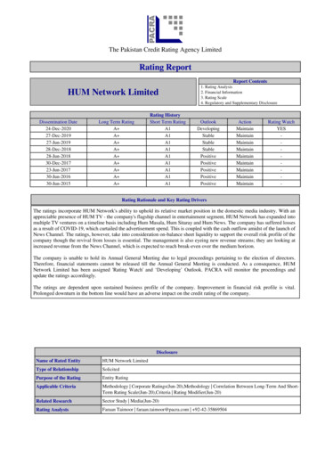
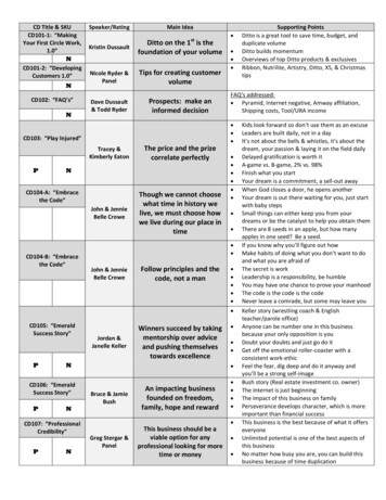
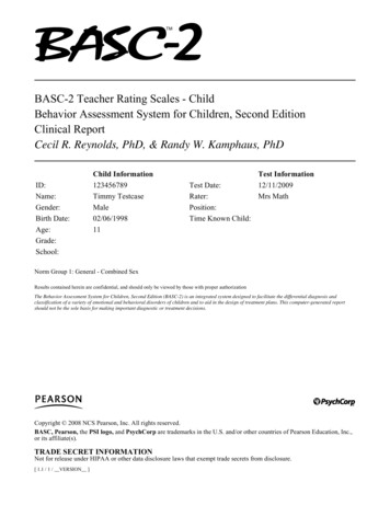
AHRI STANDARD 260 (I-P)-2017In the example presented in Figure 1, there are two Sound Components present, ducted discharge and free inletcombined with casing radiated. The ducted discharge sound component affects or defines the source strength for twoof the four typical application sound paths shown below 1) the supply airborne sound and 2) the supply breakoutsound. The free inlet combined with casing radiated sound component affects or defines the source strength for the3) return airborne and 4) wall transmission application sound paths.Ducted discharge soundcomponentTypical application sound pathsTypical DuctedEquipmentFree inlet combined with casing radiated soundcomponentFigure 1. Typical Ducted Product Application2
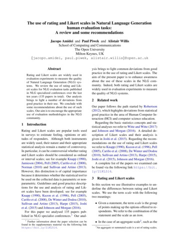
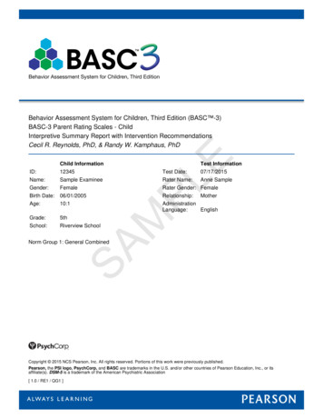
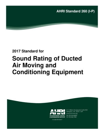
AHRI STANDARD 260 (I-P)-2017In Figure 2, a typical vertical ducted unit is presented with its Sound Components and their contributing product SoundSources. In this example, there are two Sound Components, the ducted discharge and the ducted inlet. The ducteddischarge sound component is first defined by the supply fan discharge sound in the Base Unit coupled with thedischarge plenum. The contribution of appurtenance sound from supply fan discharge airflow impinging the heatexchanger in the discharge plenum must also be added to the supply fan discharge sound. Finally, the effects of theother sources on the ducted discharge sound from the condenser fans and the refrigerant circuit must be considered.For the ducted inlet sound component, the sound from the return side of the return fan is first considered. In this case,the return side sound from the supply fan contributes as another sound source.Figure 2. Relationship Between Sound Components and Sound Sources3
AHRI STANDARD 260 (I-P)-2017Section 2. Scope2.1Scope. This standard applies to Ducted Equipment containing fans and specifies methods for determiningthe sound power ratings, using sound data for rating the various product Sound Components across the operatingrange. Mapped Sound Ratings reported are octave-band Sound Power Levels from 63 Hz to 8,000 Hz. In addition tothe stated octave band Mapped Sound Ratings, this standard can additionally be used to provide one-third octave bandMapped Sound Ratings from 50 to 10,000 Hz.2.2Exclusions. This standard does not apply to the following AHRI classes of equipment:2.2.12.2.22.2.32.2.42.2.5Outdoor heat rejection sections of equipment addressed in AHRI Standard 270 and AHRI Standard 370Non-ducted equipment addressed in AHRI Standard 300 and AHRI Standard 350Terminal equipment addressed in AHRI Standard 880 (I-P)Ductless fan coil units addressed in ANSI/AHRI Standard 440Active chilled beams addressed in AHRI Standard 1240 (I-P).Section 3. DefinitionsAll terms in this document will follow the standard industry definitions in the ASHRAE Terminology ions/free-resources/ashrae-terminology) unless otherwise defined in thissection. For acoustic related terms refer to ASA Standard Term Database /.)3.1Acoustic Baffle. A barrier that creates a well-defined duct termination and test surface for a ducted soundintensity measurement. The barrier is rigid and non-absorbing.3.2Acoustic Test Duct. A duct used to convey the sound of the unit configuration under test to the reverberationroom or intensity surface during a ducted discharge or ducted inlet sound component test. A Duct End Correctionshall be added to the sound data measured in the reverberation room or from the intensity method to account for thepresence of the duct termination.3.3Acoustic Test Duct Elbow. An elbow that may be added to the Acoustic Test Duct to facilitate testing. AnAcoustic Test Duct Elbow Correction, shall be made (in addition to the Duct End Correction) to the sound data toaccount for the presence of the Acoustic Test Duct Elbow.3.4Acoustic Test Duct Elbow Correction (E2). A correction in a frequency band to account for insertion losseffects of the elbow on the sound propagating through the Acoustic Test Duct. The table in Appendix C of this standarddefines the Acoustic Test Duct Elbow Correction.3.5Appurtenance. An addition to a Base Unit for purposes of air modulation, heat transfer, control, isolation,safety, static pressure regain, etc. Examples of Appurtenances 5.93.5.103.5.113.5.123.5.134Coil(s)Electric heater(s)Air filter(s)Damper(s)Moisture eliminator(s)Fan-motor drive(s)Gas heat exchanger(s)Inlet or discharge plenaAir mixing device(s)Flow straightener(s)Modulating device(s) in the fan inlet/dischargeApplication duct geometry(s) (such as duct elbow configurations)Alternate unit casing construction(s) (such as double walled, lined, perforated face)
AHRI STANDARD 260 (I-P)-20173.6Air-conditioner. One or more factory-made assemblies which normally include an evaporator or cooling coil,a compressor and condenser combination, and may include a heating function. Where such equipment is provided inmore than one assembly, the separated assemblies shall be designed to be used together.3.7Base Unit. A factory-made encased assembly consisting of one or more fans meant to be connected to a ductand other necessary equipment to perform one or more of the functions of circulating, cleaning, heating, cooling,humidifying, and mixing of air, but which may or may not include a source of heating or cooling.3.8Comparison Method. A method of determining Sound Power Level by comparing the average SoundPressure Level produced in the room to a Reference Sound Source of known Sound Power Level output. Thedifference in Sound Power Level is equal to the difference in Sound Pressure Level when conditions in the room arethe same for both sets of measurements.3.9Ducted Equipment. Heating, ventilating and air conditioning equipment having one or more supply fanswhich employ ductwork to convey the conditioned air to and/or from the desired spa
_ AHRI STANDARD 260 (I-P)-2017 1 SOUND RATING OF DUCTED AIR MOVING AND CONDITIONING EQUIPMENT Section 1. Purpose 1.1 Purpose.The purpose of this standard is to establish for the indoor portions of factory-assembled ducted air