Transcription
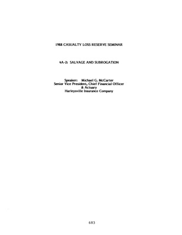
SURPLUS and SALVAGE PROJECTSHere's What It CostsFor less than 175, including a new engine, you can have Pow'r Pup rolling inyour yard or garden. You can hold costsbelow this figure by doing all the workyourself, or you can buy some of theharder-to-make components listed so thatconstruction becomes primarily an assembly job. Your actual cost may thereforerange from below 175 to 350, and yourfinished Pow'r Pup will be comparable tocommercial garden tractors selling at 500to 600.SuburbanTractorWill: mow the lawn—haul leaves—do light grading—bulldoze snow—roll the lawn—plow garden—pull a discor harrow—cultivate crops—pull a seeder—tow a sledBy S. S. MINERNOT a toy, but a real man-sized tool, thePow'r Pup goes a step beyond the straddle-type tractors now in widespread useand brings to the home workshopper, forhome construction, a rugged, simple, and economical machine for yard and garden work—and for leisure enjoyment too. Many Searstractor attachments will fit it, and you canbuild it for 175 or less.Based on used car parts (widely availablein junk yards) and various components fromSears Roebuck Co., it is extremely stable andmaneuverable. With three speeds forwardplus reverse, it will do any job from lighthauling to heavy plowing. The design callsprincipally for cutting, drilling, and weldingoperations. By special arrangement, a sup-plier has been established for components youmay wish to buy rather than make (seeMaterials List).The design is flexible enough to permit awide choice of automotive parts: you couldbase a small tractor design on almost anymanual-shift transmission and symmetricalrear end, and many small air-cooled enginesfrom 3 to 10 hp would be suitable. However,any departure from the design given herewill require careful study of the problems involved. If you make changes, keep in mindthat the ready-made parts listed will fit onlythe Pow'r Pup as designed.Your First Step in building the Pow'r Pupis to locate the used drive-train parts fromthe right vintage Ford. These need not bein first class condition when you buy themand probably will not be, but be sure youget, from one source or another, all the essen-
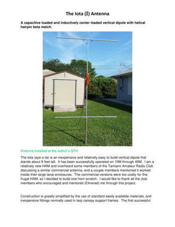
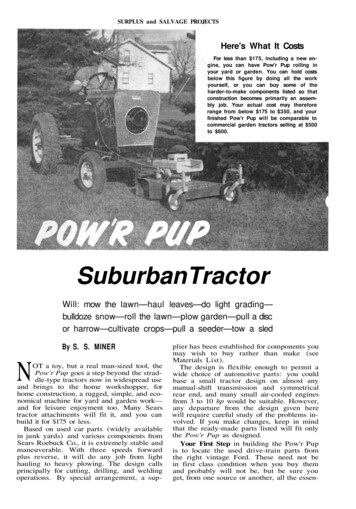
121SURPLUS and SALVAGE PROJECTSCraft PrintProject No. 321TRACTOR STEERING WHEEL ADAPTEDTO STUDE STEERING GEAR3 TO 10 UP AIRCOOLED ENGINETRACTOR SEATAND SPRINGTHROTTLEA-FRAME7 . 5 0 / 1 5 OR 16KNOBBY REAR TIRES2- STAGE SPEEDREDUCTION & SLIPPINGBELT CLUTCHMOTOR MOUNT'51 TO'53 STUDEBAKERSTEERING COMPONENTS38" TREADLOCKHEED MASTEBBRAKE CYLINDER33 70 48 FORD REAR ENDAND DRIVE 5HAFT,'32 TO '38 TRANSMISSIONDRIVE SHAFT AND AXLESSHORTENEDBATTERY SPACEIF NEEDED16X4 FRONTWHEELSRETAININGCOLLAR5 2 " WHEELBASEROLL PINRETAINING COLLARtial parts: a transmission, driveshaft andhousing, universal joint and joint cover, andrear end complete with drums and internalbrake parts. Lay all this loot out on theground somewhere and clean off the outside(it will probably be pretty dirty) with aputty knife and kerosene, or use a commercial degreaser.Before taking the parts into your workshop drain the rear end and transmission.Then remove the two axle housings from thedifferential housing. In these earlier Fords,the bevel pinion gear at the inner end ofthe axle shaft is forged directly on the endof the axle itself, hence the axle housing mustbe removed from the differential housing, andthe differential carrier must be taken apartin order to withdraw the axles. Disassemblethe rear end, clean up the axles and housingspreparatory to working on them, and unfastenthe backing plates and lay them aside.First Job is to Cut the spring perch arm(Fig. 2B) off each axle housing. Hack saw itas close as possible to the housing boltingflanges. Then cut a section out of the axlehousing itself close to the bolting flange (Fig.3A) with a hack saw, or in a power cut-offsaw if one is available. The amount to beremoved will depend upon two things: therear wheel tread of the original car, and thetractor tread width desired. Half the difference between these two dimensions is theamount to cut out. Make these cuts at 90 to the centerline of the housing.Check one of the brake backing plates tosee that it is not bent, then bolt the cut-off
SURPLUS and SALVAGE PROJECTShousing end to it. Support this on blockingand clamp the axle housing in assembled position with three 1/4-in. rods, hooked at one endand threaded at the other (Fig. 3). Checkwith a carpenter's square and steel tape todetermine parallelism and proper centeringof the backing plate and bell flange. Be sureto align the wheel cylinder opposite one holeof the bell flange so that when assembly iscompleted the wheel cylinders will be at thetop on each side.An alternate alignment method is to clampthe bell flange of the axle housing to the faceplate of a large lathe and support the cut-offhousing end in aligned position on an arbor.In either case, once proper alignment hasbeen achieved, weld the two parts together,tack-welding first on opposite sides to avoiddistortion. Shorten both axle housings in thismanner.There are Three Methods (Fig. 3B) forshortening the axles themselves: 1. Cut themoff to the desired length, retaper and threadthe ends; 2. Cut a section out and butt-weldthe remaining portions together; and 3. Cuta section out, slip a perforated sleeve overthe cut ends, and weld together. For the amateur the third method is easiest but has thedisadvantage (with the Ford axle) that theinner shaft bearing and other parts must be
SURPLUS and SALVAGE PROJECTSslipped over the axle before the sleeve iswelded on, and they can never be removed.The second method is best for those with thenecessary welding skill but no lathe.Choose the method best suited to yourskills and tools, then shorten both axles bythe same amount that you shortened thehousings.Similar problems will be encountered inshortening the driveshaft and torque tube.The front end of the Ford torque tube contains a roller bearing race; therefore theportion removed must be back of this, preferably at the rear end of the tube (Fig. 3). Boltthe rear tube-flange to the differential housing and lay the assembly on a flat surface tosecure proper alignment while welding.Since both ends of the Ford driveshaftare splined, the method chosen for shorten-ing it will probably be #2 or #3 (above),rather than # 1 , to avoid the problem of resplining a cut-off end. The sleeve method willbe satisfactory for this shortening operationas it will not interfere with assembly or disassembly. Remember to remove the sameamount from the shaft as from the tube.After the shortening operations are completed, coat all parts with a film of greaseand reassemble. Now, before going furtherwith the reassembly, check the brake drums,shoes, and cylinders—these will probablyneed reconditioning. Worn shoes can be relined or replaced (see Materials List), andscored drums can be turned at your localautomotive repair shop. Finish the assemblyof the rear end after overhauling the brakes.Next Job is the Frame (Fig. 4). If you aregoing to take this part of the job to a com-MATERIALS LIST— POW'R PUP
SURPLUS and SALVAGE PROJECTSmercial welding shop, you will save time andmoney if you get all parts cut to length first.Cut front axle parts at this same time, andhave both welding jobs done in one visit to thewelder. Check the drawings to determine according to your facilities which holes in thevarious weldments you will drill before welding, and which afterwards. Take pains to getthe frame corners square and the side railsparallel when clamping up, as there will beno way of correcting a crooked frame afterwelding. Note that in the boxed constructionof the front cross member and the front axlethe angle iron flanges are lapped so as tokeep a 2-in. vertical dimension through theseparts.Before welding on the spindle bushing supports to the axle ends, make the spindle bushings (Fig. 4A) and position them in the supports when clamping up, to make it possibleto check the spindle and caster angles.Bend the Wheel Spindles to a 105 angle(Fig. 4B), first heating them with a weldingtorch to a bright red at the point of bend.Then weld heavy steel washers to the spindleto form the shoulders (Fig. 4B). Weld theaxle pivot pin to the front cross member,spaced from it with a 1/4-in.-thick pad, sothat the axle and front cross member willlie in the same plane. Slip the axle onto thepivot pin and secure the retaining collar witha 1/4-in. bolt (Fig. 4C).It may be necessary to ream or hone outthe spindle bushings because of distortioncaused by welding. Make the fit of the spindlein the bushings fairly free, then drill and tapZerk fitting holes in the rear sides of thebushings. Install the front wheels and spindlesnow, withr brass thrust washers where shown(Fig. 4A), and fasten the wheel retainingcollars with 3/16-in. roll pins.Make the motor mount according to Fig. 4Dfor the Sears 5.75 engine—otherwise modifyit to suit whatever engine you have chosen.Prop the Rear End of the frame up at theproper height (10 in.). Notch the transmission bell with a hacksaw to clear the frameside rails (Fig. 5), then set the transmissionin place. Make two short sleeves (Fig. 5) andsecure them with 3/8-in. bolts (in the oldclutch pivot holes in the transmission) toholes drilled in the tractor frame. These support the front end of the transmission. Itsrear end is supported on two clips (Fig. 4D)and bolted there with 1/2-in bolts.Bring the rear end and driveshaft intoposition, engage the universal joint, and center up the differential housing in the frame.Jam four pieces of 1 x 1 x 1/8-in. angle ironunder the tapered axle-housings and weldthem in place. Mark and drill holes for theU-bolts (Fig. 4D), then fasten the whole rearend in solidly. Now you can put on the automobile rear wheels and lug tires, and roll theunit about the shop on its own wheels.Make a clamping plate (Fig. 3) and securethe Sears tractor spring and seat on the driveshaft housing. Later you can slide this backor forward to get the best position. Heat theshift lever to a cherry red at two places, andbend it to the dog-leg shape shown in Fig. 2.You will have to cut off the end, too, andre-thread it for the shift knob.Now for the Steering. The mechanismused was taken in its entirety from a 1952Studebaker (any Stude, '51 through '53, hasthe right gear). Be sure to get the steeringknuckle arms, both tie rods, the connectingrod, steering gear box, the end of the intermediate arm, and six tie rod ends. Cut theknuckle arms and weld them to collars (Fig.4A) so that the tie rod end centers will be4 in. from the spindle center lines. Cut the tierods in two, and lengthen them to 29 in. by
SURPLUS and SALVAGE PROJECTSwelding in pieces of 1/2-in. pipe. Cut the connecting rod and weld in a 6-in. piece of 3/8-in.rod bent to a 10 angle.Cut the pitman arm in two, lap it, andweld it to a 4-in. radius. Make the equalizingbar of 1/2 x 1-1/2-in. HRS.Weld the cut-off endsof the Stude intermediate steering arm to theequalizer bar, making certain you get thetapered holes big end up (Fig. 4E). Make thesteering gear bracket and fasten it to thetransmission housing in place of the old inspection plate. Cut the Stude steering columnoff 1-1/2-in. above the steering box, make theadapter to take the Sears steering column,and drill for 3/16-in. roll pins. The adapter willjust fill the space between the steering boxand the A-frame sleeve, a piece of 3/4-in. I.D.tubing welded to two pieces of 1 x 1 x 1/8-in.angle iron (Fig. 6). Assemble the steeringmechanism, adjust the drag link length toproduce a 25 knuckle arm angle (Fig. 4A),and pin the knuckle collars to the spindleswith two 3/16-in. roll pins each. This operationshould be performed with steering wheel centered and front wheels pointed straight ahead.The Drive Mechanism is a two-stage reduction lowering engine speed (3600 rpm) to 375rpm at the transmission input shaft. The Vbelted first stage functions as a clutch; thesecond stage is chain, for high torque. Makethe jackshaft arm (Fig. 5A) out of 1/2 x1-1/2HRS welded to a piece of 2-1/4-in. O.D. x1-3/4in. I.D. steel tubing. Make the jackshaft carrier out of the same 1/2 x 1-1/2 HRS stock.Turna shoulder on the hub of the 6-in. diameterV-belt pulley to receive the 15 tooth sprocket(which will have to be bored out for thispurpose) and braze the sprocket in place.
SURPLUS and SALVAGE PROJECTSPress two flanged bronze bushings in thebore of the pulley, and mount the pulley onthe carrier with a 2-1/4-in. long x 5/8-in diameter shoulder screw as the shaft itself. Thenassemble this mechanism, with the chain adjusted to about 1/2-in. slack.Make the clutch parts next (Fig. 5B), assemble them, and bolt the toggle bracket andbracket stay to the transmission housing.If you are using the Sears engine, you can
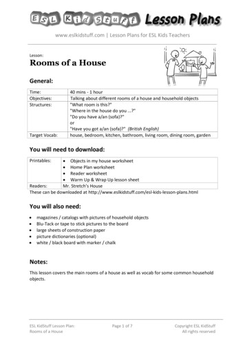
SURPLUS and SALVAGE PROJECTSWith a 5.75-hp engine, the Pow'r Pup makes lightwork of a heavy job, turning an 8-in.-wide furrow8 in. deep in medium sod with the Sears 6-in. plow.position it on the mount according to Figs.2 & 5. With other engines it will be necessary to check clearances on all sides of theengine and alignment of the drive pulley withthe jackshaft pulley before drilling themounting holes.To avoid interference with the grille, makea diagonal extension for the air cleaner (Fig.2) if your engine requires it.Make the Hood Frame (Fig. 7) of 3/16 x 1in. HRS and 3/8-in. HRS rod bent and weldedtogether. Cover it with sheet aluminum (seeMaterials List) carefully bent around theframe and secured at the bottom with #10-24rh screws and nuts. Trim the metal farenough from the frame edge so you can formit around the frame members to finish off andsecure it. Make the grille of 1/2-in. expandedmetal, or perforated aluminum sheet, andsecure it in place with #10 rh screws 1/2 in.long, and nuts.Make a 10-in. diameter ring of 1/4-in. or 3/8in. steel rod and braze it to the surface of thegrille, centering it laterally and positioningit vertically so as to clear the starting mechanism of the engine. Then cut out the portionof the grille inside the ring, hammer down thecut edges and cover them with braze wherenecessary. If your grille is aluminum, simplytrim it about 3/4 in. inside the ring and formit back over the ring.Place the Hood in position on the tractorand push it backward far enough so thestarter pull rope is freely accessible throughthe grille opening, then mark for, and drilland tap, the hood pivot-bolt holes (Fig. 4D).Then locate and bolt on (or weld) the rearhood support clips (Fig. 4).Make the brake pedal (Fig. 3), of 1/2 x 1-in.HRS and pivot it to the right side of theframe. Mount a Lockheed (or similar) master cylinder well back on the frame and makea %-in. diameter brake push rod to connectthe pedal with the cylinder. Connect the master cylinder by means of regular steel tubebrake line, including a tee fitting, to both rearwheel brake cylinders.Install a throttle control (see MaterialsList) on the A-frame and connect it to theengine carburetor. Use a similar control forthe choke, if desired.This Completes the Mechanical Work onthe Pow'r Pup. Now clean up the whole machine and paint it with good quality machineenamel (see Materials List). Before startingthe tractor, service it completely.The following article will tell how to makeand use the various attachments the Pow'rPup is designed for.
SURPLUS and SALVAGE PROJECTSPutting Pow'r Pupto WorkPart 2Mowing the lawn is not achore—it's fun with Pow'rPup.Castering wheelsmake it possible to pushmost mowers. Separatemower engine is a greatadvantage when workingaround trees and whenbacking up. The mowerkeeps on cutting, regardless of tractor speed.WHEN you have completed the mechanical work on Pow'r Pup, as describedin the preceding article, there is oneadditional feature, the rear wheel fenders,that should be added. These protect you frombeing jostled against the wheels when ridingon rough or muddy ground.Make them out of 1/2-in. black iron pipe(Fig. 5A), covered with sheet metal. Aftercutting the pipe to the required lengths, bendthe four long pieces with a plumber's hickeyto the radius shown. File or grind the endsof the transverse pieces to fit between thecurved upright members and weld them inplace.Make the four 1/4 x2in. hot rolled steel clipsand bolt them to the bottom ends of the fenderframes. Then weld theclips to the brake backing plates, positioning thetop pipe of the fenderframe about 1 in. abovethe tire. Cover the frameswith 16 gage black ironsheet, securing it with#10 x 1/2-in. self tappingscrews. Smooth up allrough edges on the fenders, then paint them tomatch the tractor.You Can Use Pow'rPup, with a variety ofplows, mowers, and other gardening tools already on the market, many of which areavailable second hand. For lawnmowing,either pull or push-type reel mowers or rotary mowers can be adapted for use. Fig. 1shows a Sears Roebuck 24-in. rotary mowerattached to the front axle of the tractor withthe hitch in Fig. 5C. Several Sears mowerscan be used with this hitch or with slightmodifications of it.Make this hitch of 2 x 2 x 1/4-in. angle iron,cut, drilled, and welded as shown. Attach theSears mower to it with the 1/4 x 2-in. HRSstrap. The clamping plates (Fig. 5C) permitthe mower to be lined up with either the leftor right wheels of thetractor for cutting alongshrubbery and walls. Thefront end of the Searsmower is supported withtwo castering forks andbrackets (see MaterialsList) bolted to the holesoriginally provided forthe adjustable mowerwheels. The mowerwheels themselves can bemounted in the forks,using 3/8-in. bolts as axles.Lead the mower throttlecontrol back to a convenient point on the hood, asseen in Fig. 1.Rear-Attaching Imple-
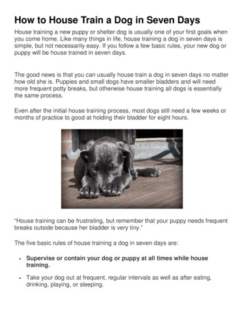
SURPLUS and SALVAGE PROJECTS129Grading is another heavy job Pow'r Pup revels in. Shown is theSears snow blade, used here for smoothing off recent earth fill.When winter comes, Pow'r Pup really comes into its own, takingall the strain out of that winter back breaker, snow removal.
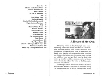
130SURPLUS and SALVAGE PROJECTSSmall-scale farming is well within the scope of Pow'rPup. You can plow over an acre a day, and disk ittoo, doing a first-class job of seedbed preparation.Thorough disking breaks up the clods so small rootlets can get a start. Note the straightened liftinghandle. Pulling it forward lifts the implement (plowor disk) when turning at the end of the row.ments should be hitched to the tractor towbar (Fig. 3). If you wish to use Sears gardentractor implements, make the adapter shownin Fig. 5B, which provides the sloping surfacerequired by the Sears implement hitch. Mountthe adapter on the center of the tow bar formost implements, but toward the right sidefor the plow, so the right wheels of the tractorwill run in the old furrow, while the plowshare cuts a new furrow and throws the dirtdirectly behind the right wheel (Fig. 6).It will be necessary to straighten the handleof the Sears implement hitch so it will missthe right fender when the handle is swungforward. Do this with a welding torch, orsimply cut off the bent part with a hacksaw.To use the Sears bulldozer with Pow'r Pup,make the adapter (Fig. 5D) using a piece ofthe Sears 'dozer hitch with a welded-on strap.Bolt this to the implement cljps on the tractorfront axle. Bend the 'dozer operating handleto the right to clear the tractor hood (Fig. 4).For a Decorative Finishing Touch, addthe Pow'r Pup emblem to the sides of thehood, following the 2-in.-sq. layout in Fig. 2.Reverse the design (except for the name) onthe left side of the hood so the Pup will bepulling forward.Whatever you use Pow'r Pup for, remember it is a real machine, not a toy. Study Fig.3 to see why it is necessary always to hitchpull-loads below the axle center. Most instances of turning tractors over come from ignoring this simple rule. Pow'r Pup, with itslow-slung weight and spread-out wheelbase,is a very stable tractor, much more so thanthe average straddle-type garden tractor withits high center of gravity. So use care andcommon sense, and you will derive years ofpleasure and service from Pow'r Pup.Sears ImplementsUseable with Pow'r Pup*24-in. Mower (or similar style)W99A9125N*6-in. Plow*30-in. Disc HarrowW32F9812N,*42-in. Snow BladeW32F9813NW32F9810N34-in. Drag HarrowW32F9814NStraddle-Row CultivatorW32F9817N*Caster fork and bracket (one RH, oneLH req'd)575PAS26— from 32F54SIN mower —Caster wheels and tire (2 req'd)9936M*3-point plow hitchW32F9811C(Also, any pull-tool such as carts, seeders,rollers, etc.)*These implements and parts are seen in the photographs accompanying this article.
SURPLUS and SALVAGE PROJECTS mercial welding shop, you will save time and money if you get all parts cut to length first. Cut front axle parts at this same time, and have both welding jobs done in one visit to the welder. Check the drawings to determine ac-cording to your facilities which h