Transcription
Alveo Card Out-of-BandManagement Specificationfor Server BMCUser GuideUG1363 (v1.1) February 14, 2020
Revision HistoryRevision HistoryThe following table shows the revision history for this document.Revision SummarySection02/14/2020 Version 1.1General updatesRevised outline of documentTable 1: Slave Adresses and Corresponding ProtocolsRevised table to remove slave address 0x64 and 0x66andinclude slave address 0x50.Chapter 3: IPMI FRU ImplementationChanged titleTemperature LimitsRevised table to be card specific.Alveo PCIe InformationIncluded to capture the PCIe information for Alveo U200,U250, U280, and U50 cards.Satellite Controller Firmware VersionAdded to provide information on the latest SC firmware.07/17/2019 Version 2019.1Initial release.UG1363 (v1.1) February 14, 2020OOB Management SpecificationN/ASend Feedbackwww.xilinx.com2
Table of ContentsRevision History.2Chapter 1: Introduction. 5Satellite Controller.5Chapter 2: Card Management Interfaces. 7Out-of-Band Communication. 8Chapter 3: IPMI FRU Implementation.13Block Write. 14Block Read.15Chapter 4: I2C/SMBus Implementation and Protocol Recap . 16Read Byte. 17Read Word.17Block Read.17Block Write Block Read. 18Chapter 5: I2C/SMBus Commands.19Command Code Definition.19FRU Data.20Block Write. 21Block Read.21Maximum DIMM Temperature.21Board Temperature.22Board Power Consumption.22(MSP432) Firmware Version. 23FPGA Die Temperature. 24Maximum QSFP Temperature. 24Chapter 6: PLDM Implementation. 26Terminus Locator PDR. 26Numeric Sensor PDR.27UG1363 (v1.1) February 14, 2020OOB Management SpecificationSend Feedbackwww.xilinx.com3
Sensor Auxiliary Names PDR. 32Temperature Limits.34Sample PLDM Transaction. 34Appendix A: Additional Resources and Legal Notices. 38Xilinx Resources.38Documentation Navigator and Design Hubs.38Alveo PCIe Information.38Satellite Controller Firmware Version. 39References.40Please Read: Important Legal Notices. 40UG1363 (v1.1) February 14, 2020OOB Management SpecificationSend Feedbackwww.xilinx.com4
Chapter 1IntroductionThis document describes out-of-band (OOB) support available for the U200, U250, U280, andU50 Alveo Data Center cards. OOB support is provided by satellite controller firmware thatruns on TI's MSP432 MCU. The underlying protocol supported is platform level data model(PLDM) over the management component transport protocol (MCTP) over the systemmanagement bus (SMbus).Satellite ControllerThe satellite controller firmware runs on TI’s MSP432 device and the underlying RTOS isFreeRTOS. The satellite controller firmware is an essential component of Alveo cardmanagement, providing in-band and OOB communication mechanisms. The MSP432 device,sensor, and peripherals reside on the auxilary power domain.UG1363 (v1.1) February 14, 2020OOB Management SpecificationSend Feedbackwww.xilinx.com5
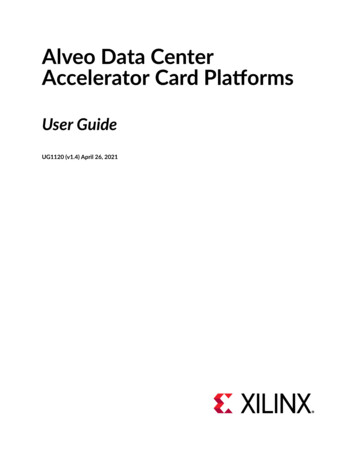
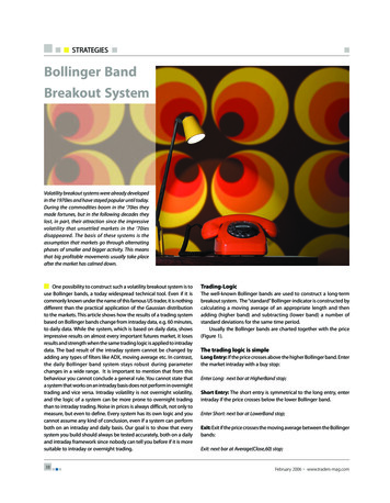
Chapter 1: IntroductionFigure 1: Satellite Controller BlockIn-Band ManagementFor Eng Bring-up OnlyDisabled in ReleaseOut of Band ManagementHost OSDebugUARTConsoleServer BMCPCIeSMBus/I2CVoltage RegulatorLTC3884UARTFPGAI2C2LM96036SE 98Ch 0Ch 1UARTMSP 432 MCUSatellite ControllerI2C1BoardtemperaturesensorsSE 98SE 98I2C0Card ManagementControllerCMCFanControllerfor FGPAI2CMUXEEPROMFor logs &factory dataPCA9536I/Oexpanderfor BSLCh 2DIMMDIMMDIMMDIMMCh 3Ch 0I2CMUXCh 1Ch 2DIMMtemperaturesensorsQSFP 0TemperaturesensorQSFP 1TemperaturesensorSI 570OSCX23545-112119UG1363 (v1.1) February 14, 2020OOB Management SpecificationSend Feedbackwww.xilinx.com6
Chapter 2Card Management InterfacesXilinx Alveo Data Center cards achieve card management using two interfaces: OOB communication channel: The satellite controller communicates with the serverbaseboard management controller (BMC) via SMBus/I2C interface to provide OOB cardmanagement functionalities. In-band communication channel: The card management controller (CMC) communicates withthe host server via the PCIe interface to provide in-band management features. The CMCfirmware, running in MicroBlaze , and satellite controller firmware, running in MSP432,communicates via the UART channel using a Xilinx proprietary protocol. All sensor data ispassed on to the CMC by the satellite controller firmware through this in-band channel.The following figure shows the high-level block functional diagram of Alveo cards.UG1363 (v1.1) February 14, 2020OOB Management SpecificationSend Feedbackwww.xilinx.com7
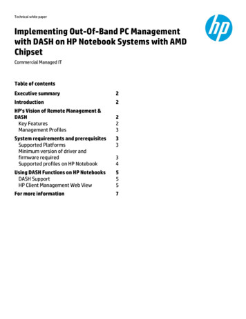
Chapter 2: Card Management InterfacesFigure 2: Satellite Communication Firmware (inside MSP432) and Card ManagementController (inside FPGA)Main PowerDomainAlways On DevicesDevicesXILINX FPGA3.3V AUX PowerDomainUser DSAUARTSerialRX/TXUARTXilinx DSASatellite ControllerMSP432AXI BridgeI2COut-of-BandChannelIn-BandChannelPCIe ShellPCIeSMBusPCIe Edge ConnectorI2CPCIe HostBaseboard ManagementControllerX23546-112119Out-of-Band CommunicationWhen installed in a server, the satellite controller firmware communicates with server BMC. Themain purpose of OOB communication is to respond to requests that originate from server BMC.It uses this information to take action related to power and thermal management (i.e., to ramp-upfans or send requests to throttle down power consumption). The MSP432 and the sensors andperipherals it accesses reside on the AUX 3.3V always-on power domain.OOB communication occurs via the physical medium of SMBus/I2C. The following table liststhree I2C slave addresses, each supporting different protocols/features.UG1363 (v1.1) February 14, 2020OOB Management SpecificationSend Feedbackwww.xilinx.com8
Chapter 2: Card Management InterfacesTable 1: Slave Adresses and Corresponding ProtocolsI2C Slave Address (7-bit)I2C SlaveAddress (8-bit)Protocol/Features Supported0x500xA0IPMI FRU data0x650xCAI2C Commands0x670xCEPLDM/MCTPI2C FRU Only CommandSatellite controller firmware supports IPMI field replaceable unit (FRU) data read at I2C slaveaddress addr: 0x50 (0xA0 in 8-bit). For FRU data access, 2-byte addressing mode is supportedand the contents of FRU data are explained in UG1378 Alveo FRU Specfication.I2C/SMBus CommunicationSatellite controller firmware supports I2C/SMBus protocol based OOB communication at I2CSlave address addr: 0x65 (0xCA in 8-bit). It provides support for server BMC that does notaccept PLDM or distributed management task force (DMTF) specifications. The followinginformation is exposed via I2C/SMBus protocol: FRU data information Thermal sensors such as FPGA, board, maximum DIMM, and maximum QSFP. Board power consumption MSP432 firmware version numberThe following is a comprehensive list of all OOB commands supported by satellite controllerfirmware adhering to the PLDM over MCTP over SMBus Protocol.UG1363 (v1.1) February 14, 2020OOB Management SpecificationSend Feedbackwww.xilinx.com9
Chapter 2: Card Management InterfacesTable 2: Supported Custom I2C/SMBus CommandsCommandCodeSensorName80h for write00h for readFRU dataSMBusNumber ofTransactio Responsen TypeBytesBlock writereadRequestWrite: ACKCommand code: 0x80will be sent Data Byte 0: FRU offset LSby I2C driver. byteData byte 1: FRU offset MSbyteData byte 2: length ( 256)Example: 0x01 0x10 0x20 Get 32 bytes of FRU addressstarting at 0x0110Read; length Command code: 0x0is set by writecommand.01h02h03hMaximumDIMMtemperatureRead bytesBoardtemperatureRead bytesBoard powerconsumptionRead words1Command code: 0x01Data Byte(s): N/AResponseThe FRU read request arrivein two or more parts:Part 1: Request to read thecommon header.Part 2 or later: Request toread actual FRU contents.Note: Default requestcombination (i.e., when writeData bytes 0, 1 and 2 are all0x0), entire FRU contents willbe returned.Requested length of FRUdata from the start offset willbe returned.Byte 0: maximum DIMMtemperature valueNote: MSP432 calculates themaximum DIMMtemperature of all DIMMspresent and provide singlesensor information.1Command code: 0x02Byte 0: Board temperatureData byte(s): N/A2Command code: 0x03uint 16 value;Data byte(s): N/AByte 0: LS byteByte 1: MS byteMSP432firmwareversion(satellitecontroller)Read bytes05hFPGA dietemperatureRead bytes106hMaximumQSFPtemperatureRead bytes104h4Command code: 0x04Byte 0: Version;Data byte(s): N/AByte1: Major revision;Byte2: Minor revision;Byte3: 0x0 (Reserved)Command code: 0x05Byte 0: FPGA temperatureData byte(s): N/ACommand code: 0x06Data byte(s): N/AByte 0: Maximum QSFPtemperatureNote: MSP432 calculates theMAX QSFP temperature of allQSFP modules present andprovides single sensorinformation.See Chapter 3: IPMI FRU Implementation for more Implementation level details.UG1363 (v1.1) February 14, 2020OOB Management SpecificationSend Feedbackwww.xilinx.com10
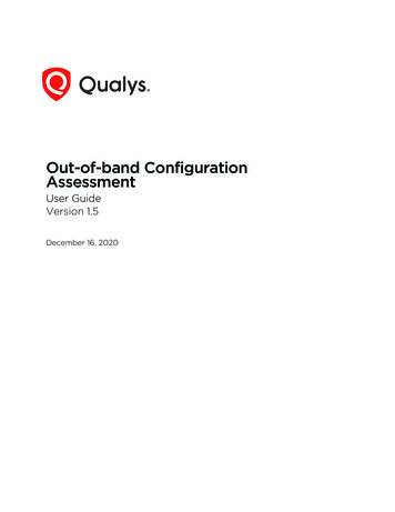
Chapter 2: Card Management InterfacesPLDM Over MCTP Over SMBus ProtocolSatellite controller firmware supports the MCTP/PLDM protocol via I2C Slave address 0x67(0xCE in 8-bit). OOB implementation adheres to PLDM Base Specification (DSP240) and PLDMfor Platform Monitoring and Control Specification (DSP0248).The following figure illustrates the PLDM over MCTP over SMBus binding specification stack.Figure 3: PLDM Over MCTP Over SMBus Binding Specification StackApplicationLayerManagement Controller(BMC or Host Processor)PLDMNC-SIMCTPControl ProtocolProtocol LayerManagement Component Transport Protocol(MCTP)TransportLayerMCTP over SMBus/I2CBinding(MSP 432)Physical LayerSMBus/I2CDeviceX23542-011620The following sensor readings are reported via PLDM OOB: FPGA temperature (fan controller remote temperature) Board temperature (fan controller local temperature )UG1363 (v1.1) February 14, 2020OOB Management SpecificationSend Feedbackwww.xilinx.com11
Chapter 2: Card Management Interfaces QSFP0 temperature QSFP1 temperatureThe following PLDM commands are supported in the satellite controller firmware:Table 3: List of Supported PLDM Commands and DescriptionsCommandIDDescriptionSetTID0x01Sets terminus ID (TID) for a PLDM terminus.GetTID0x02Returns the present TID setting for a PLDM terminus.GetPLDMVersion0x03Returns the PLDM base specification versions that the PLDMterminus supports, as well as the PLDM type specificationversions supported for each PLDM type.GetPLDMTypes0x04Enables management controllers to discover the PLDM typecapabilities supported by the PLDM terminus and get a listof the supported PLDM types.GetPLDMCommands0x04Enables management controllers to discover the PLDMcommand capabilities supported by the PLDM terminus fora specific PLDM type and version, as a responder.GetSensorReading0x11Returns the present reading and threshold event statevalues from a numeric sensor, as well as the operating stateof the sensor itselfGetSensorThresholds0x13Returns the present threshold settings for a PLDM numericsensor.GetPDRRepositoryInfo0x50Returns information about the size and number of recordsin the PDR repository of a particular PLDM terminus andtime stamps that indicate the last time an update to therepository occurred.GetPDR0x51Returns individual PDRs from a PDR repository. The recordis identified by the PDR record handle value that is passed inthe request. The command can also be used to dump all thePDRs within a PDR repository.These PLDM commands are categorized into type 0 and type 2, as detailed in the following table.Table 4: Supported Type 0 and Type 2 PLDM CommandsPLDM Type 0 CommandsPLDM Type 2 CommandsSetTID (0x01)SetTID (0x01)GetTID (0x02)GetTID (0x02)GetPLDMVersion (0x03)GetSensorReading (0x11)GetPLDMTypes (0x04)GetSensorThresholds (0x12)GetPLDMCommands (0x05)GetPDRRepositoryInfo (0x50)UG1363 (v1.1) February 14, 2020OOB Management SpecificationSend Feedbackwww.xilinx.com12
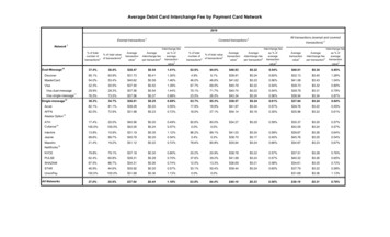
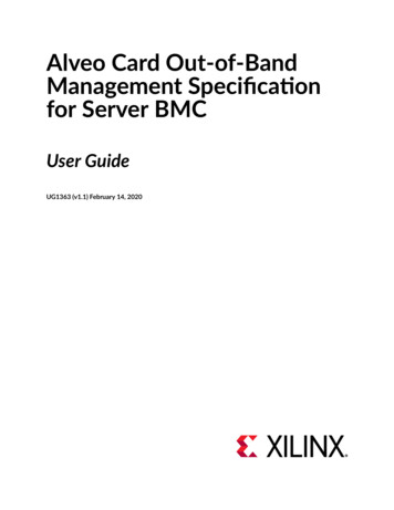
Chapter 3IPMI FRU ImplementationSatellite controller firmware exposes FRU data via a dedicated I2C slave address 0x50 (0xA0 in8-bit). All FRU data is compliant with Intelligent Platform Management Interface (IPMI) FRUspecification [Ref 1]. Satellite controller firmware emulates the traditional EEPROM's FRU datawithin the firmware to enable server BMCs that are traditionally used to interface with a nonprivate EEPROM that resides in the same I2C bus, along with satellite controllers.Accessing this FRU data follows I2C/SMBus block write block read, where block write provides a2-byte FRU offset (address byte 0 or LS Byte and address byte 1 MS Byte) and block readretrives FRU data. The SMBus transaction, with repeated start option, will be used to fetch allFRU data.The maximum response bytes per transaction is 256 bytes, as set by the underlying I2C driver.This implies that to fetch a FRU data length of 300 bytes, the server BMC is expected to sendtwo repeated START transactions. For the first transaction, the satellite controller firmware sends256 FRU bytes. For the second transaction, 44 FRU bytes 212 bytes of 0xFF are sent.Figure 4: Random ReadRandom ReadStartDeviceAddress1st, 2nd WordAddress nWriteStartDeviceAddressStopReadSDA LineDATA nMSBLSBR/WACKACKACKNOACKX23543-112119Format is as follows:START, SA W, addr-byte0, addr-byte1, RepeatedSTART, SA R, BYTE0, BYTE1 BYTEN, STOPWhere:addr-byte0][addr-byte1] are FRU offsets (block writes)and:[BYTE0][BYTE1] [BYTEN] are FRU data response (block reads)UG1363 (v1.1) February 14, 2020OOB Management SpecificationSend Feedbackwww.xilinx.com13
Chapter 3: IPMI FRU ImplementationNote: 2-byte FRU offset follows [LS Byte] [MS Byte].Example of Read FRU Data Starting at Offset 0x0 Block Write Operation: [N] 0x64 0x00 0x00[I2C Bus Number N ] [I2C Slave 0x64] [FRU Offset LS Byte] [FRUOffset MS Byte] Block Read Operation: [N] 0x64[I2C Bus Number N ] [I2C Slave 0x64]Example of Read FRU Data Starting at Offset 50 Block Write Operation: [N] 0x64 0x32 0x00[I2C Bus Number N ] [I2C Slave 0x64] [FRU Offset LS Byte] [FRUOffset MS Byte] Block Read Operation: [N] 0x64[I2C Bus Number N ] [I2C Slave 0x64]Block WriteTable 5: Block Write, Server BMC RequestServer BMC RequestData Bytes[Byte 0] [Byte 1][Byte 0] – FRU Offset LSB[Byte 1] – FRU Offset MSBTable 6: Block Write, Xilinx Alveo Card ResponseXilinx Alveo Card ResponseData BytesUG1363 (v1.1) February 14, 2020OOB Management SpecificationACK sent by I2C DriverSend Feedbackwww.xilinx.com14
Chapter 3: IPMI FRU ImplementationBlock ReadTable 7: Block Read, Server BMC RequestServer BMC RequestData bytesNA[Byte 0] – FRU offset LSB[Byte 1] – FRU offset MSBTable 8: Block Read, Xilinx Alveo Card ResponseXilinx Alveo Card ResponseData bytesUG1363 (v1.1) February 14, 2020OOB Management Specification[Byte 0] [Byte 1] . [Byte 255]]256-byte FRU dataSend Feedbackwww.xilinx.com15
Chapter 4: I2C/SMBus Implementation and Protocol RecapChapter 4I2C/SMBus Implementation andProtocol RecapThe latest sensor information is stored locally in MSP432 satellite controller firmware and isexposed on-demand to server BMC via the OOB channel I2C/SMBus, at slave address 0x65.SMBus v2.0 Specification is followed for this implementation. Each sensor data is associated withan I2C command code as mentioned in Table 15: Supported I2C/SMBus CommandsTable 9: Key to Protocol1711811SSlave AddressWAData ByteAPTable 10: SMBus Packet diagram element KeyKeyDescriptionSStart ConditionSrRepeated Start ConditionRRead (bit value of 1)WWrite (bite value of 0)xShown under a field indicates that the field is required to have the value of xAAcknowledge (this bit position may be 0 for an ACK or 1 for a NACKPStop ConditionPECPacket Error Code Master-to-slave Slave-to-master.Continuation of protocolUG1363 (v1.1) February 14, 2020OOB Management SpecificationSend Feedbackwww.xilinx.com16
Chapter 4: I2C/SMBus Implementation and Protocol RecapRead ByteTable 11: Read Byte171 181 171 181 1SSlave AddressW ACommand CodeA SSlave AddressR AData ByteA P1Read WordTable 12: Read Word171 181 171 18181 1SSlave AddressW ACommand CodeA SSlave AddressR AData Byte (Low)AData Byte (High)A P1Block ReadTable 13: Block Read171181171SSlave AddressWACommand CodeASSlave AddressR.8181.811Data Byte 1AData Byte 2A.Data Byte NAP1UG1363 (v1.1) February 14, 2020OOB Management SpecificationSend Feedbackwww.xilinx.com17
Chapter 4: I2C/SMBus Implementation and Protocol RecapBlock Write Block ReadTable 14: Block Write Block Read17SSlave Address17SSlave Address11R/W A11R/W AUG1363 (v1.1) February 14, 2020OOB Management Specification8181.81.Data Byte 1AData Byte 2A.Data Byte NA.8181.81Data
Alveo PCIe Information Included to capture the PCIe information for Alveo U200, U250, U280, and U50 cards. . OOB communication channel: The satellite controller communicates with the server baseboard management controller (BMC) via SMBus/I2C interface to provide OOB card . The following is a co