Transcription
HPE ProLiant MicroServer Gen10 Plus UserGuideAbstractThis document is for the person who installs, administers, and troubleshoots servers and storage systems.Hewlett Packard Enterprise assumes you are qualified in the servicing of computer equipment and trained inrecognizing hazards in products with hazardous energy levels.Part Number: P19356-001Published: February 2020Edition: 1
Copyright 2020 Hewlett Packard Enterprise Development LPNoticesThe information contained herein is subject to change without notice. The only warranties for Hewlett Packard Enterpriseproducts and services are set forth in the express warranty statements accompanying such products and services.Nothing herein should be construed as constituting an additional warranty. Hewlett Packard Enterprise shall not be liablefor technical or editorial errors or omissions contained herein.Confidential computer software. Valid license from Hewlett Packard Enterprise required for possession, use, or copying.Consistent with FAR 12.211 and 12.212, Commercial Computer Software, Computer Software Documentation, andTechnical Data for Commercial Items are licensed to the U.S. Government under vendor's standard commercial license.Links to third-party websites take you outside the Hewlett Packard Enterprise website. Hewlett Packard Enterprise has nocontrol over and is not responsible for information outside the Hewlett Packard Enterprise website.AcknowledgmentsClearCenter , ClearOS , and ClearVM are trademarks of ClearCenter Corporation in the United States and/or othercountries.Intel , Pentium Gold, and Xeon are trademarks of Intel Corporation in the U.S. and other countries.Linux is the registered trademark of Linus Torvalds in the U.S. and other countries.Microsoft , Windows , and Windows Server are either registered trademarks or trademarks of Microsoft Corporation inthe United States and/or other countries.Red Hat Enterprise Linux are registered trademarks of Red Hat, Inc. in the United States and other countries.VMware ESXi and VMware vSphere are registered trademarks or trademarks of VMware, Inc. in the United States andother jurisdictions.All third-party marks are property of their respective owners.
ContentsComponent identification. 6Front panel components.6Front panel LEDs and button. 7Front panel LED power fault codes. 7Rear panel components.8Rear panel LEDs. 9System board components. 10System maintenance switch descriptions. 11DIMM label identification.11Drive bay numbering. 13Drive screws.13Riser board slots.14Operations. 15Power up the server. 15Power down the server.15Removing the front bezel.15Installing the front bezel.17Removing the chassis cover. 18Installing the chassis cover. 20Removing the system board assembly. 20Installing the system board assembly. 22Setup.24Optional service. 24Initial system installation.24HPE Installation Service. 24Setting up the server.25Server orientation options.30Position the server in a horizontal orientation.30Position the server in a vertical orientation.30Operational requirements.32Site requirements.32Space and airflow requirements. 32Temperature requirements. 32Power requirements. 33Electrical grounding requirements.33Server warnings and cautions. 33Electrostatic discharge. 34POST screen options. 34Installing or deploying an operating system. 35Hardware options installation. 36Introduction.36Drive options. 363
Drive support information.36Drive installation guidelines.36Installing an LFF drive.37Installing an SFF drive. 39Memory options.42Memory population table. 43DIMM ranks .43DIMM handling guidelines.43Installing a DIMM.44Storage controller options.45Installing a Smart Array storage controller.45Configuring an HPE Smart Array Gen10 controller.47Expansion board options.48Installing an expansion board.48Internal USB device options. 52Install an internal USB device.52External HPE RDX Backup System option.53iLO enablement option.54Installing the iLO enablement option.54HPE Trusted Platform Module 2.0 Gen10 option.56Overview.56HPE Trusted Platform Module 2.0 guidelines. 56Installing and enabling the HPE TPM 2.0 Gen10 option. 57Cabling. 62Cabling overview .62Storage cabling. 62Four-bay drive cabling: Onboard SATA controller cabling.62Four-bay drive cabling: Smart Array controller cabling.63Fan cabling.64Software and configuration utilities.65Server mode.65Product QuickSpecs. 65Active Health System Viewer. 65Active Health System. 65HPE iLO 5.66iLO Federation. 67iLO RESTful API. 67RESTful Interface Tool.67iLO Amplifier Pack. 67Integrated Management Log. 68Intelligent Provisioning.68Intelligent Provisioning operation.68Management security.69Scripting Toolkit for Windows and Linux. 69UEFI System Utilities. 70Selecting the boot mode .70Secure Boot.71Launching the Embedded UEFI Shell .71HPE Smart Storage Administrator. 72HPE InfoSight for servers . 72USB support.734
External USB functionality.73Redundant ROM support. 73Safety and security benefits. 73Keeping the system current. 73Updating firmware or system ROM. 73Drivers.76Software and firmware.76Operating system version support. 76HPE Pointnext Portfolio.76Proactive notifications.77Troubleshooting.78NMI functionality.78Troubleshooting resources. 78System battery replacement.79System battery information.79Removing and replacing the system battery.79Safety, warranty, and regulatory information. 82Regulatory information. 82Notices for Eurasian Economic Union. 82Turkey RoHS material content declaration. 83Ukraine RoHS material content declaration.83Warranty information. 83Specifications. 84Environmental specifications.84Mechanical specifications.85Websites.86Support and other resources. 87Accessing Hewlett Packard Enterprise Support.87ClearCARE technical support.87Accessing updates. 87Customer self repair.88Remote support. 88Documentation feedback. 895
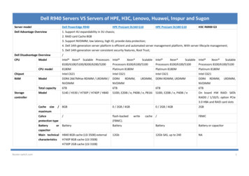
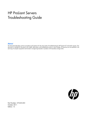
Component identificationThis chapter describes the external and internal server features and components.Front panel componentsItemComponentDescription1Drive bays (4, behind the front bezel)By default, the drive bays support 3.5-inch LFF SATA drives.To support 2.5-inch SFF drives, install the SFF drive converteroption.2Front bezelTo access the drive bays, remove this bezel.3USB 3.2 Gen 2 Type-A ports1Connect USB devices. These ports are backwards compatible withearlier USB Type-A version devices.1 These ports are also known as SuperSpeed USB 10 Gb/s ports. The appropriate cable and compatible hardware are required to takeadvantage of the 10 Gb/s data transfer speed.6Component identification
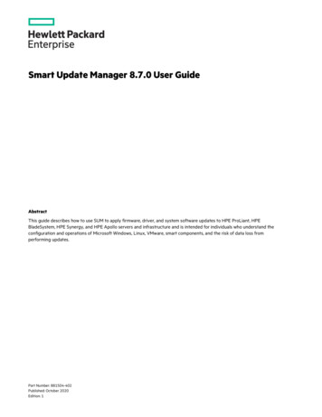
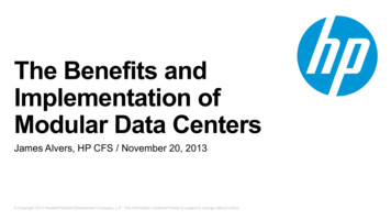
Front panel LEDs and buttonItemDescriptionStatusDefinition1Drive activity LED1Flashing greenOngoing drive activityOffNo drive activitySolid greenLinked to networkFlashing greenNetwork activeOffNo network activitySolid greenNormalFlashing greeniLO is rebootingFlashing amberSystem degraded4Flashing redSystem critical4Solid greenSystem on and normal operationFlashing greenPerforming power-on sequenceAmberSystem in standbyOffNo power present5234NIC status LED2, 3Health LED3Power on/Standby buttonand system power LED31 This LED only reflects the status of drives that are connected to the onboard SATA port.2 This LED reflects the status of the onboard NIC ports managed by the embedded Intel I350-AM4 Ethernet Controller.3 When these LEDs flash simultaneously, a power fault has occurred. For more information, see Front panel LED power fault codes.4 If the health LED indicates a degraded or critical state, review the system IML or use iLO to review the system health status.5 Facility power is not present, power cord is not attached, or power supply failure has occurred.Front panel LED power fault codesThe following table provides a list of power fault codes, and the subsystems that are affected. Not all power faults areused by all servers.Component identification7
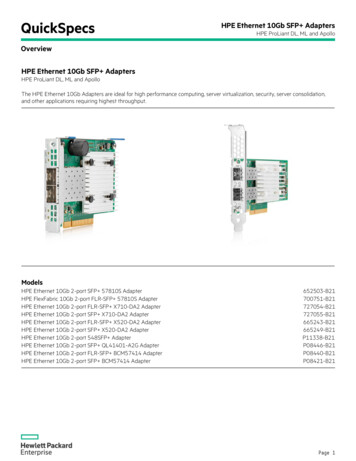
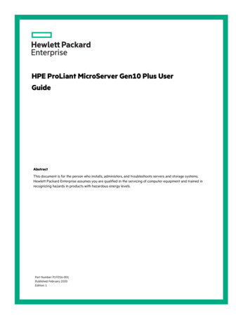
SubsystemLED behaviorSystem board1 flashProcessor2 flashesMemory3 flashesRiser board PCIe slots4 flashesFlexibleLOM5 flashesRemovable HPE Smart Array SR Gen10 controller6 flashesSystem board PCIe slots7 flashesPower backplane or storage backplane8 flashesPower supply9 flashesRear panel componentsItemComponentDescription1Padlock eyeTo lock the chassis cover and prevent access to the internalcomponents, attach a padlock here.2iLO dedicated network portTo connect iLO to a dedicated management network, connect astandard Ethernet cable here. This port requires the installation of theiLO enablement option.3Kensington security slotTo secure the server to a heavy or immovable object, connect anantitheft security cable here.4USB 3.2 Gen 1 Type-A ports1Connect USB devices. These ports are backwards compatible withearlier USB Type-A version devices.Table Continued8Component identification
ItemComponentDescription5System QR code labelTo access the server mobile product page (https://www.hpe.com/qref/microservergen10plus), use a QR code scanner app in yoursmartphone to scan this label. This mobile page contains links to serversetup information, spare part numbers, QuickSpecs, troubleshootingresources, and other useful product links.6DisplayPort 1.0Connects to a h
3 Kensington security slot To secure the server to a heavy or immovable object, connect an antitheft security cable here. 4 USB 3.2 Gen 1 Type-A ports1 Connect USB devices. These ports are backwards compatible with earlier USB Type-A ve