Transcription
HPE ProLiant DL380 Gen10 Server UserGuideAbstractThis document is for the person who installs, administers, and troubleshoots servers and storagesystems. Hewlett Packard Enterprise assumes you are qualified in the servicing of computerequipment and trained in recognizing hazards in products with hazardous energy levels.Part Number: 868990-001Published: July 2017Edition: 1
Copyright 2017, Hewlett Packard Enterprise Development LPNoticesThe information contained herein is subject to change without notice. The only warranties for Hewlett PackardEnterprise products and services are set forth in the express warranty statements accompanying suchproducts and services. Nothing herein should be construed as constituting an additional warranty. HewlettPackard Enterprise shall not be liable for technical or editorial errors or omissions contained herein.Confidential computer software. Valid license from Hewlett Packard Enterprise required for possession, use,or copying. Consistent with FAR 12.211 and 12.212, Commercial Computer Software, Computer SoftwareDocumentation, and Technical Data for Commercial Items are licensed to the U.S. Government undervendor's standard commercial license.Links to third-party websites take you outside the Hewlett Packard Enterprise website. Hewlett PackardEnterprise has no control over and is not responsible for information outside the Hewlett Packard Enterprisewebsite.
ContentsComponent identification. 8Front panel components.8Front panel LEDs and buttons.10UID button functionality.14Power fault LEDs. 14Systems Insight Display LEDs.14Systems Insight Display combined LED descriptions.15Rear panel components. 17Rear panel LEDs. 18System board components.19System maintenance switch descriptions. 20Processor, heatsink, and socket components. 21Drives. 21SAS/SATA drive components and LEDs.22NVMe drive components and LEDs.23uFF drive components and LEDs. 23Fan bay numbering.24Drive box identification. 25Drive bay numbering. 26Drive bay numbering: Smart Array controller.26Drive bay numbering: SAS expander. 28Drive bay numbering: NVMe drives. 30uFF drive bay numbering.31Operations.32Powering up the server.32Power down the server .32Extend the server from the rack. 32Extending the server from the rack.33Removing the server from the rack. 34Installing the server into the rack.34Remove the access panel. 36Installing the access panel. 36Removing the fan cage.36Installing the fan cage.37Removing the air baffle or midplane drive cage. 37Installing the air baffle.39Removing a riser cage.40Removing a riser slot blank. 41Removing the hard drive blank.41Releasing the cable management arm .42Accessing the Systems Insight Display. 42Setup.44HPE support services. 44Setup overview. 44Operational requirements. 44Space and airflow requirements. 44Contents3
Temperature requirements.45Power requirements.46Electrical grounding requirements. 46Server warnings and cautions. 46Rack warnings. 47Electrostatic discharge.47Server box contents.48Installing hardware options . 48Configuring the server. 48Installing or deploying an operating system.48Registering the server.49Hardware options installation. 50Product QuickSpecs. 50Introduction.50Installing the bezel and bezel lock.50Power supply options. 51Hot-plug power supply calculations. 51Installing a redundant hot-plug power supply. 51Drive options.52Drive guidelines. 52Supported drive carriers. 53Installing a hot-plug SAS or SATA drive.53Installing an NVMe drive.54Installing a uFF drive and SCM drive carrier. 55Installing an M.2 drive.56Fan options.57Installing high-performance fans.58Memory options. 59DIMM population information.59HPE Smart Memory speed information. 60DIMM label identification.60Installing a DIMM. 61Controller options. 62Installing a storage controller.62Installing a Universal Media Bay. 63Drive cage options.65Installing a front 8NVMe SSD Express Bay drive cage. 65Installing a front 6SFF SAS/SATA 2NVMe Premium drive cage. 67Installing airflow labels. 68Installing a front 8SFF SAS/SATA drive cage in box 1. 69Installing a front 8SFF SAS/SATA drive cage in box 2. 71Installing a front 2SFF NVMe/SAS/SATA Premium drive cage.72Installing a midplane 4LFF SAS/SATA drive cage.75Installing a rear 2SFF SAS/SATA drive cage in the primary or secondary riser. 77Installing a rear 2SFF SAS/SATA drive cage over the power supplies.79Installing a rear 3LFF SAS/SATA drive cage. 82Riser and riser cage options.84Installing primary and secondary risers. 84Installing tertiary risers.85Installing a secondary riser cage. 86Installing a tertiary riser cage.87Installing the 2NVMe slimSAS riser option. 89Installing the 8NVMe slimSAS riser option. 90Expansion slots. 914Contents
Supported PCIe form factors. 91Installing expansion boards. 92Installing a 12G SAS Expander Card. 94Installing a GPU card.96Installing an intrusion detection switch. 100Installing a Smart Storage Battery.101Installing a rear serial port interface. 102Installing a Systems Insight Display. 104Installing a FlexibleLOM adapter. 106Installing a 1U or high-performance heatsink. 108Installing a processor.110HPE Trusted Platform Module 2.0 Gen10 Option.112Overview. 112HPE Trusted Platform Module 2.0 Guidelines. 113Disabling Chipset-TPM. 113Installing and enabling the HPE TPM 2.0 Gen10 Kit. 113Installing the Trusted Platform Module board.113Enabling the Trusted Platform Module. 116Retaining the recovery key/password. 117Cabling.118HPE ProLiant Gen10 DL Servers Storage Cabling Guidelines. 118Cabling diagrams.118Cable routing: Front 2SFF drive option for SFF.120Cable routing: Front 2SFF drive option for LFF. 121Cable routing: Front 2SFF drive options (3 position cable). 122Cable routing: Front 8SFF drive options.123Cable routing: Front 8SFF NVMe/SAS premium drive option. 125Cable routing: Front 8SFF NVMe drive options.125Cable routing: Front 2SFF NVMe drive option for SFF.127Cable routing: Front 2SFF NVMe drive option for LFF. 128Cable routing: Midplane 4LFF drive option.128Cable routing: Rear 3LFF drive option.129Cable routing: Rear 2SFF drive options. 129Cable routing: HPE 12G SAS Expander to a controller.130Cable routing: Systems Insight Display. 131Software and configuration utilities.132Server mode. 132Product QuickSpecs. 132Active Health System Viewer. 132Active Health System.132Active Health System data collection.133Active Health System Log.133HPE iLO 5.133iLO Federation. 133iLO Service Port.134iLO RESTful API. 134RESTful Interface Tool.134iLO Amplifier Pack. 135Intelligent Provisioning.135Intelligent Provisioning operation.135Management Security.136Scripting Toolkit for Windows and Linux. 136Contents5
UEFI System Utilities.136Selecting the boot mode . 137Secure Boot. 137Launching the Embedded UEFI Shell .138HPE Smart Storage Administrator.138USB support. 139External USB functionality. 139Redundant ROM support.139Safety and security benefits.139Keeping the system current.139Updating firmware or system ROM.139Service Pack for ProLiant. 139Updating firmware from the System Utilities . 141Updating the firmware from the UEFI Embedded Shell . 141Online Flash components. 141Drivers. 142Software and firmware.142Operating System Version Support. 142HPE Technology Service Portfolio. 142Change control and proactive notification.143Troubleshooting.144NMI functionality. 144Troubleshooting resources. 144Safety, warranty, and regulatory information.145Safety and regulatory compliance. 145Warranty information. 145Regulatory information. 145Belarus Kazakhstan Russia marking. 145Turkey RoHS material content declaration. 146Ukraine RoHS material content declaration.146Specifications. 147Environmental specifications. 147Mechanical specifications.147Power supply specifications. 148HPE 500W Flex Slot Platinum Hot-plug Power Supply. 148HPE 800W Flex Slot Platinum Hot-plug Power Supply. 149HPE 800W Flex Slot Titanium Plus Hot-plug Power Supply. 150HPE 800W Flex Slot Universal Hot-plug Power Supply. 151HPE 800W Flex Slot -48VDC Hot-plug Power Supply. 152HPE 1600W Flex Slot Platinum Hot Plug Power Supply. 153Support and other resources. 154Accessing Hewlett Packard Enterprise Support. 154Accessing updates. 154Customer self repair. 154Remote support. 155Warranty information. 155Regulatory information. 156Documentation feedback.1566Contents
Documentation feedback. 157Contents7
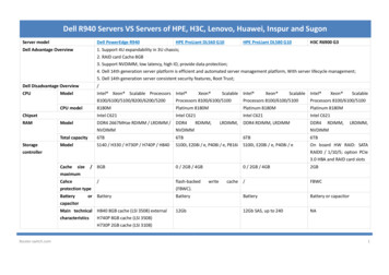
Component identificationFront panel componentsSFF front panel componentsItemDescription1Box 1 (optional drives or universal media bay)2Box 2 (optional drives)3Box 3 Drives 1-84Serial label pull tab or optional Systems Insight Display5iLO service port6USB 3.0 portUniversal media bay components8ItemDescription1USB 2.0 port2Video display port3Optical disk drive (optional)4Drives (optional)Component identification
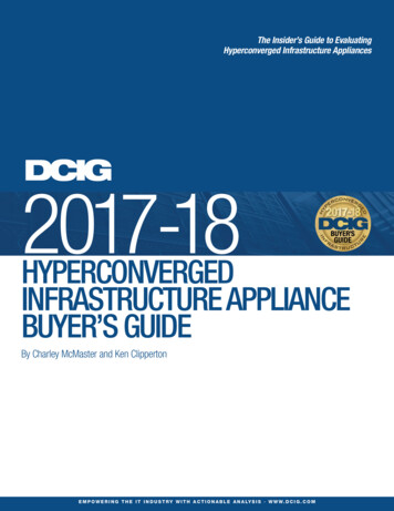
12-drive LFF front panel componentsItemDescription1Drive bays8-drive LFF model front panel componentsItemDescription1Drives (optional)2LFF power switch module3Drive baysLFF power switch module componentsComponent identification9
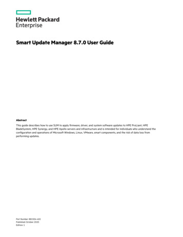
ItemDescription1Optical disk drive2Serial label pull tab3USB 3.0 port4iLO service port5Video display portFront panel LEDs and buttonsSFF front panel LEDs and buttonItemDescriptionStatus1Power On/Standby button andsystem power LED*Solid green System onFlashing green (1 Hz/cycle per sec) Performingpower on sequenceSolid amber System in standbyOff No power present†2Health LED*Solid green NormalFlashing green (1 Hz/cycle per sec) iLO is rebootingFlashing amber System degradedFlashing red (1 Hz/cycle per sec) System critical**Table Continued10Front panel LEDs and buttons
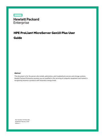
ItemDescriptionStatus3NIC status LED*Solid green Link to networkFlashing green (1 Hz/cycle per sec) Network activeOff No network activity4UID button/LED*Solid blue ActivatedFlashing blue: 1 Hz/cycle per sec Remote management orfirmware upgrade in progress4 Hz/cycle per sec iLO manual reboot sequenceinitiated8 Hz/cycle per sec iLO manual reboot sequencein progressOff Deactivated*When all four LEDs described in this table flash simultaneously, a power fault has occurred. For moreinformation, see "Power fault LEDs."**If the health LED indicates a degraded or critical state, review the system IML or use iLO to review thesystem health status.†Facility power is not present, power cord is not attached, no power supplies are installed, power supplyfailure has occurred, or the power button cable is disconnected.LFF 12-drive model front panel LEDs and buttonComponent identification11
ItemDescriptionStatus1Health LED*Solid green NormalFlashing green (1 Hz/cycle per sec) iLO is rebootingFlashing amber System degradedFlashing red (1 Hz/cycle per sec) System critical**2Power On/Standby button andsystem power LED*Solid green System onFlashing green (1 Hz/cycle per sec) Performingpower on sequenceSolid amber System in standbyOff No power present†3NIC status LED*Solid green Link to networkFlashing green (1 Hz/cycle per sec) Network activeOff No network activity4UID button/LED*Solid blue ActivatedFlashing blue: 1 Hz/cycle per sec Remote management orfirmware upgrade in progress4 Hz/cycle pe
Guide Part Number: 868990-001 Published: July 2017 Edition: 1 Abstract This document is for the person who installs, administers, and troubleshoots servers and storage systems. Hewlett Packard Enterprise assumes you are qualified in the servicing of computer equipment and trained in reco