Transcription
PRTR Estimation Manual13. Valve Manufacturing IndustryJanuary 2001Revised: March 2002Japan Valve Manufacturers’ Association
Contents1.Class I Designated Chemical Substances (Class I Substances).12.Methods of Calculating PRTR Releases and Transfers .23.Flow Diagram of Valve Manufacturing Processes and Release points .43.1. Copper alloy valve (casting).43.2. Iron casting valve manufacturing process .53.3. Steel casting valve manufacturing process.63.4. Stainless steel valve manufacturing process (casting).73.5. Faucet manufacturing process .83.6. Forged valve manufacturing process.94.Methods and Examples of Calculating the Releases and Transfersin the Manufacturing Processes.104.1. Melting process .104.2. Casting process .134.3. Machining process.164.4. Process of removing burr.184.5. Degreasing and cleaning process.204.6. Plating process.234.7. Assembly process .274.8. Painting process.29Appendix: Emission factor for Class I Substances related tovalve manufacturing processes.32
1. Class I Designated Chemical Substances (Class I Substances)The main raw materials used in valve manufacturing processes, containing 1mass percent or more of Class I Substances( 0.1 mass percent or more for SpecificClass I Substances) are shown in Table 1.Table 1 Class I Substances related to valve manufacturing processesNo.Raw materialUseCabinetorder no.CAS No.Name of substance1Casting materialBronze casting2307439-92-1Lead2Casting materialBrass casting2307439-92-1Lead3Casting materialBronze casting1787782-49-2Selenium4Casting materialIron casting3117439-96-5Manganese5Casting materialIron casting687440-47-3Chromium6Casting materialIron casting3467439-98-7Molybdenum7Casting materialIron casting2317440-02-0Nickel8Phenol resinMolding/core sand binding1175-07-0Acetaldehyde9Phenol resinMolding/core sand binding31050-00-0Formaldehyde10Phenol resinMolding/core sand binding266108-95-2Phenol11Phenol resinMolding/core sand binding631330-20-7Xylene12Furan resinMolding/core sand binding266108-95-2Phenol13Furan resinMolding/core sand binding31050-00-0Formaldehyde14Degreasing /cleaningDegreasing /cleaning14575-09-2Dichloromethane15Metallic raw materialRaw material of bronze2307439-92-1Lead16Metallic raw materialRaw material of brass2307439-92-1Lead17Metallic raw materialRaw material of bronze1787782-49-2Selenium18Metallic raw materialRaw material of iron3117439-96-5Manganese19Metallic raw materialRaw material of iron687440-47-3Chromium20Metallic raw materialRaw material of iron3467439-98-7Molybdenum21Metallic raw materialRaw material of iron2317440-02-0Nickel22Plating liquidChromium plating liquid697789-00-6Chromium (Ⅵ)comp.23Plating liquidChromium plating liquid681308-38-9Chromium (Ⅲ)comp.24Plating liquidChromium plating liquid30410043-35-3Boron & its comp.Nickel compounds25Plating liquidNickel plating liquid23226Plating liquidCopper plating liquid2073333-67-310101-98-17758-98-727Solvent (adhesive)Adhesion of resin parts227108-88-3Toluene28Solvent (painting)Painting of products227108-88-3Toluene29Solvent (painting)Painting of products631330-20-7XyleneCopper salts(water soluble)Note 1: Although chromium(III) compounds (dichromium trioxide) are not used as theraw material they are generated as a result of wastewater treatment of the platingsolution containing chromium(VI) compounds (chromium trioxide).1
2. Methods of Calculating PRTR Releases and TransfersThe chemical substances of which PRTR releases and transfers should becalculated are Class I Designated Chemical Substances contained 1 percent or morein raw materials (in case of specific Class I Designated Chemical Substances 0.1percent or more).For some facilities where emission factors shown in this manual are not suitable,calculation should be done by their own data, for example, by actual measurement,etc.The amounts released, transferred, and shipped as products in eachmanufacturing process are calculated according to the following methods:[1]Estimation of the releases to air:(annual quantity of Class I Substances handled) (emission factor to air)[2]Estimation of the releases to water bodies:(annual quantity of Class I Substances handled) (emission factor to water bodies)Note: Releases to water bodies are calculated as the amount released, and releases tosewerage are calculated as the amount transferred.[3]Releases to soils: 0Note: As no release to soils occurs in the valve manufacturing process, the amountreleased to soils is calculated as 0.[4]Estimation of the transfers as waste:(annual amount of waste containing the Class I Substances entrusted to wastedisposal dealer) (content of Class I Substances in waste)[5]Estimation of the Amount recycled:(annual amount of waste containing the Class I Substances handed over to recycledealers) (content of the Class I Substances)[6]Estimation of the amount shipped as products(annual quantity of materials handled containing the Class I Substances) (contentof Class I Substances) – (amount released to air) – (amount released/transferred towater bodies) – (the amount released to soils (0)) – (amount transferred as waste) –(amount recycled)2
The annual quantity of Class I Substances handled is calculated using thefollowing methods:[1](annual quantity of materials handled) (stock at beginning of term) (annual quantity purchased) – (stock at end of term)[2]Content:The average content based on the content of the Class I Designated ChemicalSubstances for each purchased lot of material should be used. However, when themaximum content is known and there is not a significant difference from theaverage content, the maximum content may be used for the average content. (Underthe PRTR system, the maximum value is used instead of the intermediate value,based on the principle that risks should not be estimated at the lower side.)Concerning the alloy in the melting process, the contents of the Class ISubstances in the alloy are used.[3](Annual quantity of Class I Substances handled) (annual handled quantity of materials containing Class I Substances) (content ofClass I Substances)3
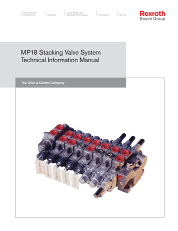
3. Flow Diagram of Valve Manufacturing Processes and Release pointsMain valve manufacturing processes and release points are shown as follows.3.1. Copper alloy valve (casting)Flow of manufacturing processRelease pointMaterial(Return material)Molding sandTo air (emission)Mold makingCore makingMeltingprocessWaste / Recycle(mineral residue dust)CoreinsertionTo air (emission)Mold register(Return material)abatementCastingprocessWaste(binder residue)PouringRecycle(cutting, grinding waste)Mold AssemblyFigure 1. Copper alloy valve(casting)4
3.2. Iron casting valve manufacturing processFlow of manufacturing processRelease pointMaterial(Return material)Molding sandTo air (emission)Mold makingMeltingprocessCore makingWaste / Recycle(mineral residue dust)CoreinsertionTo air (emission)Mold register(Return material)abatementCastingprocessWaste(binder residue)PouringRecycle(cutting, grinding waste)Mold releaseFinishingMachiningprocessTo air (vaporization anddispersion of aste (waste solution)Figure 2. Iron casting valve manufacturing process5
3.3. Steel casting valve manufacturing processFlow of manufacturing processRelease pointMaterial(Return material)Molding sandTo air (emission)Mold makingWaste / Recycle(mineral residue dust)MeltingprocessCore makingCoreinsertionTo air (emission)Mold register(Return material)cutting, grindingwasteCastingprocessWaste(binder residue)PouringMold releaseHeattreatmentTo air (vaporization of solvent )To air (vaporization of solvent)PaintingprocessDegrease /cleaningprocessAssemblyWaste (waste solution)InspectionFinishingWaste (waste solution)MachiningprocessRecycle(cutting, grinding waste)ShipmentFigure 3. Steel casting valve manufacturing process6
3.4. Stainless steel valve manufacturing process (casting)Flow of manufacturing processRelease pointMaterial(Return material)Molding sandTo air (emission)Mold makingMeltingprocessCore makingWaste / Recycle(mineral residue dust)CoreinsertionTo air (emission)Mold register(Return material)cutting, grindingwasteCastingprocessWaste(binder residue)PouringHeattreatmentMold releaseFinishingTo air (vaporization of solvent )AssemblyDegrease /cleaningprocessMachiningprocessWaste (waste , grinding waste)ShipmentFigure 4. Stainless steel valve manufacturing process (casting)7
3.5. Faucet manufacturing processFlow of manufacturing processRelease pointMaterialTo air (emission)Mold making(Return material)Molding sandWaste / Recycle(mineral residue dust)MeltingprocessCore makingTo air (emission)CoreinsertionCastingprocessMold registerWasteMold release (binder residue)PouringCleaningWater bodies(wastewater)PlatingprocessFinishing(Return material)cutting, g, grinding waste)Waste / Recycle(waste solution)AssemblyprocessShipmentInspectionFigure5. Faucet manufacturing process8To air(vaporization of solvent)
3.6. Forged valve manufacturing processFlow of manufacturing processRelease pointMaterialHeatingCuttingForgingBurr removalprocessRecycling(forging junk)Recycling (cutting, grinding waste)SurfacetreatmentMachiningprocessTo air (vaporization of solvent)Waste(waste solution)Degrease /cleaning processAssemblyShipmentInspectionFigure 6. Forged valve manufacturing process9
4. Methods and Examples of Calculating the Releases and Transfers in theManufacturing ProcessesCalculation examples of releases and transfers in valve manufacturingprocesses are those that follow.In other processes not mentioned here, raw materials or materials containingClass I Substances are not used usually, or if used, the amount used is very small, sotheir examples are omitted.4.1. Melting processIn the melting process, release to air, transfer as waste, the amount recycled andthe amount shipped as product of Class I Substances are objectives of calculation.Main materials used in the melting process containing 1 percent or more ofClass I Designated Chemical Substances are shown in Table 4.1.1.In the melting process, content of Class I Designated Chemical Substance iscontent of Class I Substance contained in the molten alloy.However, there are some cases where other Class I Substances are contained inthe raw materials purchased by the manufacturers. Thus it should be confirmedwhether or not any other designated substances are contained in the purchased rawmaterials, along with their content.Emission factors for the main Class I Substances are shown in Table 4.1.2.[Release flow chart]Released to air (exhaust gas) [A]Material Amounthandled [M]Melting processShipped (contained in products)[F]Waste / Recycling (mineral residue / collected dust)[D][E]・Annual handled quantity of the material containing the Class I Substances: M[1] Releases to air:A [M] [content of Class I Substances] [emission factor to air][2] Releases to water bodies: B 0[3] Releases to soils: C 0[4] Transfers as waste:D [annual amount of waste containing Class I Substances handed over towaste processors] [content of Class I Substances in waste][5] Amount recycled:E [annual amount of waste containing Class I Substances handed over to10
recycle dealers] [content of Class I Substances in waste][6] Amount shipped as products:F [(M) (content of Class I Substances)] – A – D – E[7] Amount of landfills: G 0Note: The amount of landfills refers to the on-site controlled type landfills.[Releases and transfers in the melting process; : yes, : lls Table 4.1.1 Main Class I Substances related to the melting processRawNo.CabinetUsematerialorder no.CAS No.Name ofsubstance1Casting materialBronze casting2307439-92-1Lead2Casting materialBrass foundry2307439-92-1Lead3Casting materialBronze casting1787782-49-2Selenium4Casting materialIron casting3117439-96-5Manganese5Casting materialIron casting687440-47-3Chromium6Casting materialIron casting3467439-98-7Molybdenum7Casting materialIron casting2317440-02-0NickelTable 4.1.2 Emission factors of Class I Substances in the melting processNo.1234567Emission factor ofClassⅠsubstanceName ofsubstanceLead (Bronze casting)Lead ( Brass ��ir 1Water bodies0000000Note: Emission factors mentioned above are the result obtained by a survey conducted byJapan valve manufacturers’ association (2000/12).[Calculation example of amount of lead (bronze casting) released/transferred in themelting process]Since lead in the melting process is not released to water bodies/soils, the11
amount released to water bodies/land is calculated as zero.
3. Flow Diagram of Valve Manufacturing Processes and Release points Main valve manufacturing processes and release points are shown as follows. 3.1. Copper alloy valve (casting) Mold making Core making Melting process Core insertion Mold register Pouring Mold release Finishing Machining process Shipment Inspection Assembly Material (Return material)File Size: 201KBPage Count: 34