Transcription
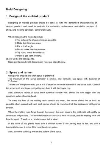
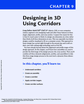
Chapter 9Designing in 3DUsing CorridorsLong before AutoCAD Civil 3D objects, CAD, or even computersCopyright 2015. John Wiley & Sons, Incorporated. All rights reserved.existed, engineers were designing roads and other linear features in threestages: alignment, profile, and cross section. I suspect the reason for thisis that it’s much easier to think of a design one dimension at a time ratherthan think of all three dimensions at once. This was especially true beforedesigns could be visualized in 3D on a computer screen. This approach tolinear design has carried right through to the present day and is still evident, even with cutting-edge technology such as Civil 3D.You have already learned about the alignment and profile stages of thisdesign approach. In this chapter, you’ll learn how assemblies are used toprovide the third stage of the design process: the cross section. Then you’llcombine all three elements (alignments, profiles, and assemblies) to takethis three-stage design process to the next level: a dynamic three-dimensional model.In this chapter, you’ll learn to: Understand corridors Create an assembly Create a corridor Apply corridor targets Create corridor surfacesChappell, Eric. AutoCAD Civil 3D 2016 Essentials : Autodesk Official Press, John Wiley & Sons, Incorporated, 2015. ProQuest Ebook etail.action?docID 2052358.Created from osu on 2017-09-25 17:43:59.
170Chapter 9 Designing in 3D Using CorridorsUnderstanding CorridorsA corridor consists of hundreds or even thousands of individual Civil 3D objectsthat are dynamically linked to one another. A good way to begin understandinghow corridors work is to study how these different components come togetherto become a 3D representation of your design.Understanding the 3D ChainCopyright 2015. John Wiley & Sons, Incorporated. All rights reserved.In Chapter 5, “Designing in 2D Using Alignments,” you used alignments to designthe 2D path of a linear feature, in this case a road. In Chapter 7, “DesigningVertically Using Profiles,” you designed the vertical path of the road using profiles.When combined, the alignment and profile form a three-dimensional pathwaycalled a 3D chain. The 3D chain serves as the backbone of your design.3D chains can actually be seen in your drawing, but only if you view the drawing from a 3D perspective, as shown in Figure 9.1.F i g u re 9 . 1 The blue lines represent 3D chains formed by combining alignments withprofiles to form a three-dimensional pathway.Because the 3D chain is dynamically linked to both the alignment and profile,a change to either one will automatically prompt a change to the 3D chain andsubsequently update the corridor.Understanding the AssemblyAn assembly is a representation of the cross-sectional geometry of the featureyou’re designing. It establishes the overall shape of the cross section and distinguishes the areas within it. For example, a typical road cross section can have areasof asphalt pavement, base material, curbs, and sidewalks, as shown in Figure 9.2.Chappell, Eric. AutoCAD Civil 3D 2016 Essentials : Autodesk Official Press, John Wiley & Sons, Incorporated, 2015. ProQuest Ebook etail.action?docID 2052358.Created from osu on 2017-09-25 17:43:59.
Understanding CorridorsF i g u re 9 . 2 A Civil 3D assembly that establishes lanes, curbs, sidewalks, and gradingThe parts of an assembly are called subassemblies. They are dynamically linkedto one another and therefore have the potential to affect one another. For example, if a curb subassembly is located at the edge of a lane subassembly, the curbsubassembly will automatically move outward if the lane width is increased.Understanding Assembly InsertionsCopyright 2015. John Wiley & Sons, Incorporated. All rights reserved.To create a corridor, Civil 3D inserts instances of an assembly along a 3D chain atregular intervals. These assembly insertions can be thought of as the ribs of the3D model, providing shape to the road one assembly at a time (see Figure 9.3).F i g u re 9 . 3 Assemblies inserted at intervals along a 3D chainBecause the assembly insertions are dynamically linked to the 3D chain, anychange to the alignment or profile will prompt a change in the corridor. Theassembly insertions are also dynamically linked to the assembly itself, so anychange to the assembly will also prompt an update to the corridor.Chappell, Eric. AutoCAD Civil 3D 2016 Essentials : Autodesk Official Press, John Wiley & Sons, Incorporated, 2015. ProQuest Ebook etail.action?docID 2052358.Created from osu on 2017-09-25 17:43:59.171
172Chapter 9 Designing in 3D Using CorridorsUnderstanding Corridor Feature LinesTo provide a framework in the longitudinal direction, Civil 3D draws feature linesfrom assembly to assembly (see Figure 9.4). The feature lines employ a coding systemto determine which points they are drawn through each time they cross an assembly.F i g u re 9 . 4 The red lines are feature lines that connect like points on each assembly insertion.Copyright 2015. John Wiley & Sons, Incorporated. All rights reserved.The feature lines are linked to the assembly insertions, which are linked to the3D chain, and so on. I’ll stop calling out relationships specifically and cover it allby saying that everything within a corridor is essentially related.Understanding the Corridor SurfaceAs you view the assembly insertions along the 3D chain previously shown inFigure 9.3, imagine this as the structural framework of a ship or an airplane. Withthe framework in place, now imagine the hull or fuselage being installed on thevessel. This is a great way to envision the role of a corridor surface (see Figure 9.5).F i g u re 9 . 5 A corridor along with its corridor surface, shown in 3D viewChappell, Eric. AutoCAD Civil 3D 2016 Essentials : Autodesk Official Press, John Wiley & Sons, Incorporated, 2015. ProQuest Ebook etail.action?docID 2052358.Created from osu on 2017-09-25 17:43:59.
Creating an Assembly173Although they appear in Prospector like other surfaces, corridor surfaces arebuilt directly from the corridor and maintain a link to the corridor. They can bedisplayed as contours, used to create surface profiles, and perform every otherfunction normally associated with surfaces.Creating an AssemblyAs mentioned previously, an assembly consists of smaller components calledsubassemblies. To create an assembly, you begin by creating an assembly baseline, which is represented by a simple vertical line with a single base-pointmarker at its midpoint. Then you proceed by inserting individual subassembliesthat represent elements such as lanes, curbs, ditches, and so on.Before building an assembly, it’s a good idea to have at least a sketch of thetypical cross section of your design so you have something to reference as youwork. Having detailed dimensions is helpful but not critical—the subassembliescan be changed with relative ease, even after the corridor has been built.Exercise 9.1: Create an AssemblyCopyright 2015. John Wiley & Sons, Incorporated. All rights reserved.In this exercise, you’ll create an assembly that represents the cross section ofthe road for the proposed residential development.1. Open the drawing named Creating an Assembly.dwg located in theChapter 09 class data folder.2. On the Home tab of the ribbon, click Assembly CreateAssembly. If you haven’t alreadydone so, downloadand install the files forChapter 9 according tothe instructions in thisbook’s Introduction.3. In the Create Assembly dialog box, enter Subdivision Road as thename. For Code Set Style, select All Codes With Hatching. Click OK.4. Click a point near the center of the top-right viewport to insert theassembly baseline.5. On the Home tab of the ribbon, click the Tool Palettes icon.6. In the Tool Palettes window, right-click the gray strip labeled ToolPalettes, and select Civil Imperial (Metric) Subassemblies.Chappell, Eric. AutoCAD Civil 3D 2016 Essentials : Autodesk Official Press, John Wiley & Sons, Incorporated, 2015. ProQuest Ebook etail.action?docID 2052358.Created from osu on 2017-09-25 17:43:59. A vertical red lineappears in yourdrawing.
174Chapter 9 Designing in 3D Using Corridors7. Click the stack of tabs at the bottom of the Tool Palettes window, andthen click Basic, as shown in Figure 9.6.Click here The Properties windowappears, and you’reprompted on the command line to select amarker point. Copyright 2015. John Wiley & Sons, Incorporated. All rights reserved.You may need to zoomin to see the circlemarkers on the lanesubassembly.Then click hereF i g u re 9 . 6 Selecting the Basic tool palette8. On the Basic tool palette, click BasicLane.9. In the Properties window, verify that Side is set to Right, and thenclick the marker at the midpoint of the assembly baseline.A lane subassembly is attached to the assembly baseline.10. On the Basic tool palette, click BasicCurbAndGutter. In theProperties window, change the value for Curb Height to 0.50 (0.15). 11. Click the upper-right circle marker on the lane subassembly youinserted earlier.A subassembly representing a curb and gutter is now attached tothe lane. 12. Press Esc to end the assembly-insertion command. Click the lanesubassembly and the curb subassembly, and then click Mirror on theribbon.This isn’t the sameMirror command thatAutoCAD softwareuses for mirroringlines, arcs, and circles.This is a special command for subassemblies, and it must beused instead of theAutoCAD version.13. Click the vertical red assembly baseline.Both sides of the assembly now display a lane and curbsubassembly.14. Save and close the drawing.You can view the results of successfully completing this exercise by openingCreating an Assembly - Complete.dwg.Chappell, Eric. AutoCAD Civil 3D 2016 Essentials : Autodesk Official Press, John Wiley & Sons, Incorporated, 2015. ProQuest Ebook etail.action?docID 2052358.Created from osu on 2017-09-25 17:43:59.
Creating a Corridor175What Are Subassemblies Made Of?Subassemblies are made up of three fundamental components: points, links, andshapes. A point is self-explanatory, a link is a line that is drawn between twopoints, and a shape is the result of three or more links forming a closed shape, asshown in the following diagram. Each point, link, and shape in a subassembly hasat least one code. These codes are used to identify the purpose of a componentand control its style, behavior, and relationship to other parts of the design. Acollection of styles that apply to multiple codes is called a code set style.ShapeLinksCopyright 2015. John Wiley & Sons, Incorporated. All rights reserved.PointsCreating a CorridorConsidering the complexity and sophistication of a corridor, the process of creating one is actually quite simple. Once the alignment, profile, and assemblyare in place, it’s just a matter of telling these three objects that they belongtogether. Of course, the design is far from complete at this point, but as you’llsee in the next exercise, creating the initial version of a corridor involves only afew steps.Exercise 9.2: Create a CorridorIn this exercise, you’ll create the initial corridor for Jordan Court.1. Open the drawing named Creating a Corridor.dwg located in theChapter 09 class data folder.2. On the Home tab of the ribbon, click Corridor.Chappell, Eric. AutoCAD Civil 3D 2016 Essentials : Autodesk Official Press, John Wiley & Sons, Incorporated, 2015. ProQuest Ebook etail.action?docID 2052358.Created from osu on 2017-09-25 17:43:59.CertificationObjective If you haven’t alreadydone so, downloadand install the files forChapter 9 according tothe instructions in thisbook’s Introduction.
176Chapter 9 Designing in 3D Using Corridors3. In the Create Corridor dialog box, do the following:a. For Name, enter Jordan Court.b. For Alignment, verify that Jordan Court is selected.c. For Profile, select Jordan Court FGCL.d. For Assembly, select Subdivision Road.e. Uncheck the box next to Set Baseline And Region Parameters. Copyright 2015. John Wiley & Sons, Incorporated. All rights reserved.Normally you wouldalso make a choice forTarget Surface, but fornow, leave this settingset to None .f. Click OK.4. Zoom in to the bottom-right viewport, and notice the corridor thathas been created there (see Figure 9.7).F i g u re 9 . 7 A portion of the newly created corridor shown in a 3D perspective5. Save and close the drawing.You can view the results of successfully completing this exercise by openingCreating a Corridor - Complete.dwg.Applying Corridor TargetsOne thing that makes corridors so powerful is their ability to interact withother objects in the drawing. Corridors are able to morph themselves into different shapes and sizes in order to respond to existing features or componentsof newly designed features. This is made possible through the use of specialChappell, Eric. AutoCAD Civil 3D 2016 Essentials : Autodesk Official Press, John Wiley & Sons, Incorporated, 2015. ProQuest Ebook etail.action?docID 2052358.Created from osu on 2017-09-25 17:43:59.
A p p l y i n g C o r r i d o r Ta r g e t ssubassemblies that can be stretched, twisted, and reconfigured as the designprogresses along the corridor. What makes these subassemblies special is thatthey utilize corridor targets.Three types of targets can be applied to a corridor: surface targets, width oroffset targets, and slope or elevation targets.Understanding Surface TargetsSurface targets are used in a number of cases where the corridor needs to interact with a surface, such as when a slope is projected from a design elevationto the point where it intercepts an existing ground surface. This is referred toas daylighting. For example, in a section of road design that is above existingground, daylighting can be used to create the embankment from the elevationof the road to the original ground elevation (see Figure 9.8).Road3:1 Slope3:1 SlopeExisting Ground SurfaceDaylight PointDaylight PointCopyright 2015. John Wiley & Sons, Incorporated. All rights reserved.F i g u re 9 . 8 A cross-section view of a road that shows the daylighting of a 3:1 slopeon either sideAlthough daylighting is the most common example of surface targeting, thereare other examples such as establishing the cross slope of an existing road, settingthe top elevation of a retaining wall, setting the depth of a pipe, and many others.Understanding Width or Offset TargetsAnother type of target used in corridor design is referred to as a width or offsettarget. As the name suggests, this type of target is used to vary the width of anobject or the distance between a point and the centerline (also known as offset).For example, an alignment can be used as a target that controls the outsideedge of a lane. As the path of the alignment moves away from the road centerline, the lane widens. As the path of the alignment moves toward the road centerline, the lane narrows (see Figure 9.9).Chappell, Eric. AutoCAD Civil 3D 2016 Essentials : Autodesk Official Press, John Wiley & Sons, Incorporated, 2015. ProQuest Ebook etail.action?docID 2052358.Created from osu on 2017-09-25 17:43:59.177
178Chapter 9 Designing in 3D Using CorridorsF i g u re 9 . 9 A width or offset target (in red) applied to a corridor to widen the lane andcreate a pull-off areaCopyright 2015. John Wiley & Sons, Incorporated. All rights reserved.In addition to alignments, you can use feature lines, survey figures, and polylines as width or offset targets. Lane widening is probably the most commonuse of a width or offset target, but there are many other uses. For example, youcan use a width or offset target to control the location of a ditch, the width of ashoulder, or the distance between a shoulder and a guardrail.Understanding Slope or Elevation TargetsSlope or elevation targets are used to control the elevations of one or more components of a corridor. For example, these targets can control the elevations of aroadside ditch to ensure that it drains to a specific point, regardless of the slopeof the adjacent road (see Figure 9.10). Profiles, feature lines, survey figures, and3D polylines can be used as this type of target.Chappell, Eric. AutoCAD Civil 3D 2016 Essentials : Autodesk Official Press, John Wiley & Sons, Incorporated, 2015. ProQuest Ebook etail.action?docID 2052358.Created from osu on 2017-09-25 17:43:59.
A p p l y i n g C o r r i d o r Ta r g e t sF i g u re 9 . 1 0 The use of a profile (3D chain shown in red) to control the elevations of a ditchCopyright 2015. John Wiley & Sons, Incorporated. All rights reserved.Tying Proposed Elevations to Existing ElevationsThe concept of daylighting is found throughout all types of land development.As I’ve mentioned, one of the fundamental activities of land development ischanging the shape of the land. This means portions of the development willhave new elevations that are above or below the existing elevations. Becausethings such as roads and parking lots aren’t much good underground and can’tsimply float in midair, there must be some way of transitioning between newelevations and existing elevations. The most economical material that can beused to construct that transition is soil, but soil isn’t stable on steep slopes.Therefore, the transition between new and existing elevations is done withrelatively mild slopes such as 3:1 (three units horizontal to one vertical). One ofthe most important components of your land-development design will be thistie-in between proposed elevations and existing elevations.Chappell, Eric. AutoCAD Civil 3D 2016 Essentials : Autodesk Official Press, John Wiley & Sons, Incorporated, 2015. ProQuest Ebook etail.action?docID 2052358.Created from osu on 2017-09-25 17:43:59.179
180Chapter 9 Designing in 3D Using CorridorsEnabling Target BehaviorBefore you can use targets within your corridor, you must apply subassembliesthat have targeting capabilities. Civil 3D comes with hundreds of subassemblies,each designed for a different purpose or application. Some of these subassemblies can use targets, and some can’t. For example, the BasicLane subassemblythat you used earlier doesn’t have the ability to target anything. So if you wouldlike to use a width or offset target to incorporate a turning lane, a pull-offarea, or some other feature into your corridor, you’ll have to use a differentsubassembly. If you haven’t alreadydone so, downloadand install the files forChapter 9 according tothe instructions in thisbook’s Introduction.Exercise 9.3: Apply Subassemblies That CanUse TargetsIn this exercise, you’ll add subassemblies that will enable the corridor lane widthto vary and the corridor to tie to an existing ground surface.1. Open the drawing named Adding Target Subassemblies.dwglocated in the Chapter 09 class data folder.2. Open the Tool Palettes window, and click the Basic tool palette.Copyright 2015. John Wiley & Sons, Incorporated. All rights reserved. You can also click theword Replace on thecommand line insteadof typing R.3. Click BasicLaneTransition. On the command line, type R and pressEnter to invoke the Replace option.4. In the upper-right viewport, click the right-lane subassembly. Whenprompted to select an attachment point for the highlighted subassembly, click the upper-left point of the curb and gutter, as shown inFigure 9.11F i g u re 9 . 1 1 Choosing the attachment point for the curb and guttersubassemblyChappell, Eric. AutoCAD Civil 3D 2016 Essentials : Autodesk Official Press, John Wiley & Sons, Incorporated, 2015. ProQuest Ebook etail.action?docID 2052358.Created from osu on 2017-09-25 17:43:59.
A p p l y i n g C o r r i d o r Ta r g e t s1815. Repeat the previous two steps for the left-lane subassembly. Thistime, pick the upper-right corner point of the left curb and guttersubassembly.6. Press Esc to clear the current selection. Click the assembly baseline(the vertical line to which the subassemblies are attached), and thenclick Assembly Properties on the ribbon.7. In the Assembly Properties dialog box, do the following:a. Click the Construction tab. Click Group (1) twice to edit thename. Type Right, and press Enter. Use the same procedure tochange the name of Group (2) to Left.b. Under the group now named Right, rename the two subassemblies Right Lane and Right Curb. Do the same for the Leftgroup, naming the subassemblies Left Lane and Left Curb.c. Click Right Lane. Then, under Input Values, scroll down andfind the Transition value. Change it to Hold Grade, ChangeOffset.Copyright 2015. John Wiley & Sons, Incorporated. All rights reserved.d. Repeat step c for Left Lane.Figure 9.12 shows the Assembly Properties dialog after you complete all the tasks in this step.F i g u re 9 . 1 2 The Assembly Properties dialog box after the groups andsubassemblies have been renamed and the properties for the lanes have been setproperly8. Click OK to close the Assembly Properties dialog box and return tothe drawing.9. On the Basic tool palette, click BasicSideSlopeCutDitch.Chappell, Eric. AutoCAD Civil 3D 2016 Essentials : Autodesk Official Press, John Wiley & Sons, Incorporated, 2015. ProQuest Ebook etail.action?docID 2052358.Created from osu on 2017-09-25 17:43:59. As the name implies,the Hold Grade, ChangeOffset setting maintains the cross gradeof the lane (whichhappens to be 2 percent) while wideningor narrowing it to thespecified distance.The assemblynow contains twoBasicLaneTransitionsubassemblies in placeof the BasicLane subassemblies. This enablestargeting so that youcan create a turning lane in the nextexercise.
182Chapter 9 Designing in 3D Using Corridors Notice that you didn’thave to set the Sideproperty to Left orRight. Civil 3D has aspecial feature thatautomatically guesseswhich side of theassembly you’re on.10. Click the marker in the upper-left corner of the Left Curb subassembly. Click the marker in the upper-right corner of the Right Curbsubassembly. The assembly should now look similar to Figure 9.13.F i g u re 9 . 1 3 The assembly with newly added BasicSideSlopeCutDitchsubassemblies on either side11. Press Esc to end the current command. Click the rightBasicSideSlopeCutDitch subassembly, and then click SubassemblyProperties on the ribbon.Copyright 2015. John Wiley & Sons, Incorporated. All rights reserved.12. On the Information tab of the Subassembly Properties dialog box,change the name to Right Daylight.13. Repeat the previous two steps for the same subassembly on the left,this time naming it Left Daylight. Take the time torename your subassemblies using logical,easy-to-remembernames. This not onlymakes it easier to keeptrack of these things asyou continue to workon your corridor, it alsohelps if you have topass your work on tosomeone else.14. Save and close the drawing.You can view the results of successfully completing this exercise by openingAdding Target Subassemblies - Complete.dwg.Assigning TargetsYou use the Target Mapping dialog box to assign targets within a corridor. Thisdialog box lists the three types of targets (surfaces, width or offset targets, andslope or elevation targets) along with subassemblies within your corridor thatare able to use each type of target (see Figure 9.14). Targets don’t have to be usedwhenever they are available. In fact, for many corridors, the majority of the targets are set to None .Chappell, Eric. AutoCAD Civil 3D 2016 Essentials : Autodesk Official Press, John Wiley & Sons, Incorporated, 2015. ProQuest Ebook etail.action?docID 2052358.Created from osu on 2017-09-25 17:43:59.
A p p l y i n g C o r r i d o r Ta r g e t s183F i g u re 9 . 1 4 The Target Mapping dialog box showing the three types of corridor targetsalong with the subassemblies that can use each type of targetCopyright 2015. John Wiley & Sons, Incorporated. All rights reserved.To assign a target, you click the cell in the Object Name column that corresponds to the subassembly you would like to set up. This displays a dialog boxwhere you can select objects in the drawing graphically or by name.Exercise 9.4: Assign Targets In this exercise, you’ll assign targets to the corridor to provide daylighting and aturn lane for Jordan Court.If you haven’t alreadydone so, downloadand install the files forChapter 9 according tothe instructions in thisbook’s Introduction.1. Open the drawing named Applying Corridor Targets.dwg locatedin the Chapter 09 class data folder.2. Click the corridor in the drawing, and then click Edit Targets on theribbon.3. When prompted to select a region, click inside the left viewport anywhere within the corridor.Corridor RegionIn step 3, you’re prompted to select a region to edit. A region is essentially a partof your corridor that begins at one station and ends at another. All corridors startout with a single region that extends the full length of the corridor. As a designevolves, however, you’ll typically break up the corridor into multiple regions.Chappell, Eric. AutoCAD Civil 3D 2016 Essentials : Autodesk Official Press, John Wiley & Sons, Incorporated, 2015. ProQuest Ebook etail.action?docID 2052358.Created from osu on 2017-09-25 17:43:59.
184Chapter 9 Designing in 3D Using Corridors This opens the SetWidth Or Offset Targetdialog box.4. In the Target Mapping dialog box, under Width Or Offset Targets,click None in the Object Name column next to the Left Lanesubassembly.5. In the Set Width Or Offset Target dialog box, under Select ObjectType To Target, select Feature Lines, Survey Figures, and Polylines.6. Click Select From Drawing. Then, in the left viewport, zoom in to thebeginning of Jordan Court where it intersects with Emerson Road.7. Click the red polyline that represents the desired path of the leftlane’s edge, and then press Enter. Copyright 2015. John Wiley & Sons, Incorporated. All rights reserved.It may seem that thered polyline is on theright side of the road,but remember that leftand right are definedwhile looking in thedirection in which thestations increase.8. Click OK twice to return to the drawing. The corridor is widened nearthe entrance, as shown in Figure 9.15. By widening the left lane thisway, you make extra room for a turning lane.F i g u re 9 . 1 5 The corridor is wider where the lane-edge polyline was targeted.9. Click within the corridor to reopen the Target Mapping dialog box.10. In the Target Mapping dialog box, click the cell next to Surfaces thatreads Click Here To Set All .11. Select EG, and click OK. Then click OK to dismiss the TargetMapping dialog box. Pan around in the lower-right viewport to viewthe 3D representation of the corridor.Chappell, Eric. AutoCAD Civil 3D 2016 Essentials : Autodesk Official Press, John Wiley & Sons, Incorporated, 2015. ProQuest Ebook etail.action?docID 2052358.Created from osu on 2017-09-25 17:43:59.
Creating Corridor SurfacesYou should now see additional geometry along the edges of thecorridor (see Figure 9.16). This represents the daylighting that hasbeen applied. The daylighting geometry is noticeably wider in someareas than in others. These are areas that are below existing groundthrough which a ditch has been constructed. This automatic creationof ditches is a function of the BasicSideSlopeCutDitch subassembly.Cut Area with DitchFill Area with No DitchF i g u re 9 . 1 6 Areas of daylighting along the corridor12. Save and close the drawing.Copyright 2015. John Wiley & Sons, Incorporated. All rights reserved.You can view the results of successfully completing this exercise by openingApplying Corridor Targets - Complete.dwg.Creating Corridor SurfacesIn Chapter 4, “Modeling the Existing Terrain Using Surfaces,” you learnedabout the benefits of using a surface to model the existing terrain. A surfaceprovided a model of the land and enabled you to do things like display contours,label elevations, and create surface profiles. Imagine having all those capabilities with a corridor as well. This is made possible through the creation of a corridor surface.Chappell, Eric. AutoCAD Civil 3D 2016 Essentials : Autodesk Official Press, John Wiley & Sons, Incorporated, 2015. ProQuest Ebook etail.action?docID 2052358.Created from osu on 2017-09-25 17:43:59.185
186Chapter 9 Designing in 3D Using CorridorsCut and FillCopyright 2015. John Wiley & Sons, Incorporated. All rights reserved.The terms cut and fill are used quite a bit in relation to land-developmentactivities. For example, in the BasicSideSlopeCutDitch subassembly, the wordcut refers to a condition where the road is below existing ground and thereforehas to project a slope upward in order to daylight. Another way to envision thisis that earth must be cut away in order to construct the road in these areas. Theopposite of cut is fill, which refers to conditions where an area must be filledin with earth to create a design feature. Cut and fill can also be used to referto quantities of earth, where cut represents the volume of earth that must beremoved to build something and fill represents the volume of earth that mustbe brought in to build something.If you haven’t alreadydone so, downloadand install the files forChapter 9 according tothe instructions in thisbook’s Introduction. Corridor surfaces are u
AutoCAD software uses for mirroring lines, arcs, and circles. This is a special com-mand for subassem - blies, and it must be used instead of the AutoCAD version. Chappell, Eric. AutoCAD Civil 3D 2016 Essentials : Autodesk Official Press, John Wile