Transcription
Course Materials- Civil Engineering- Steel StructuresSTEEL STRUCTURESEditorial BoardProf. Ajaya Kumar Nayak, BTech (NIT Rourkela), ME (IISc Bangalore), PhD(University of Southampton, UK)Course LeaderAssistant Professor (Formerly Reader)Civil Engineering Department, VSSUT, BurlaEmail: ajayanayak07@gmail.com, Ph No: 91-9777460423Prof Leena Sinha, BTech (VSSUT, Burla), MTech (NIT, Rourkela)Co-Course LeaderAssistant Professor (Formerly Lecturer)Civil Engineering Department, VSSUT, BurlaEmail: sinha.Leena@gmail.com, Ph No: 91-9437439330Prof Bjian Kumar Roy, BTech (BESU, Shibapur), MTech (BESU, Shibapur)Co-Course LeaderAssistant Professor (Formerly Lecturer)Civil Engineering Department, VSSUT, BurlaEmail: bijan.roy@rediffmail.com, Ph No: 91-9658861748Department of Civil EngineeringVeer Surendra Sai University of Technology, Burla, 768018, Odisha, IndiaUnder revision *, Funded by ETET Odisha1
Course Materials- Civil Engineering- Steel StructuresDISCLAIMERThese lecture notes are being prepared and printed for the use in training the students andpracticing engineers. No commercial use of these notes is permitted and copies of these willnot be offered for sale in any manner. Due acknowledgement has been made in the referencesections. The readers are encouraged to provide written feedbacks for improvement of coursematerials.Dr Ajaya Kumar NayakMrs Leena SinhaMr Bijan Kumar RoyUnder revision *, Funded by ETET Odisha2
Course Materials- Civil Engineering- Steel StructuresPreface to the First Edition of Lecture NotesIt is well known that the students of civil engineering particularly students in foundationcourses like steel structures are greatly handicapped due to the want of a concise andcomprehensive lecture note on the subject as a whole. A student has therefore no other waythan to go through a number of voluminous textbooks on each one of the various branches ofSteel Structures and in doing so he/she is very often confused about how much he/she shouldread and know. This confusion obviously leads to undue wastage of time and energy on thepart of the student.With much of inspiration from our Hon’ble Vice Chancellor Prof. E. Sai Baba Reddy,VSSUT, Burla we ventured to accept the task of writing this lecture notes in which anattempt has been made to discuss the fundamental principles of all the different branches ofthe subject in such a manner as to enable the student to gradually acquire a reasonably goodstandard of foundation knowledge of Steel Structures. Each individual lecture deals with aparticular branch of the subject and the extent of treatment is expected to fulfil therequirements for the Four year BTech degree course in Civil Engineering of the State andCentral Universities in India.We take this opportunity to offer our sincere thanks and deep sense of gratitude to ProfessorS S Das, Head of the Civil Engineering Department who gave us the motivation to this work.We also thank the faculty members and staffs of Civil Engineering Department VSSUT Burlafor creating stimulating environment for carrying out this work. Thanks are also due to MrMuna Kalundia of the Department of Architecture, VSSUT, Burla who prepared somediagrams contained in this lecture notes. Thanks are also due to Mr Avaya Kumar Satapathyof the Department of Civil Engineering, VSSUT, Burla who typed some parts of lecture noteswhile we are very busy in carrying out the important works for VSSUT, Burla.We shall deem our efforts successful if the lecture notes is proved useful to those for whomit is meant.VSSUT, BurlaThe 8th April, 2015Dr Ajaya Kumar NayakMrs Leena SinhaMr Bijan Kumar RoyUnder revision *, Funded by ETET Odisha3
Course Materials- Civil Engineering- Steel StructuresModule 1 Lecture 1In this lecture the course outline and the module and lecture wise breakup of the steelstructure course are discussed. Also, the list of reference books, conference papers, reportsand journals have been given.Course Outline of BCE 309 Steel Structures (3-1-0) CR-04 (IS 800-2007 and Steel Tables arepermitted in the Examination)Module I: Philosophy, concept and methods of design of steel structures, structural elements,structural steel sections, riveted and welded connections, design of tension membersModule II: Design of compression members, Design of columns, lacing and battening,Column base and foundationModule III: Design of beams, Plate Girder and Gantry GirderModule IV: Design of roof trusses.Course Prerequisites: Structural Analysis, Mechanics of Materials, Engineering MechanicsReferences1. Ram Chandra and V. Gehlot, Design of Steel Structures, Scientific Publishers,Jodhpur2. L.S. Negi, Design of Steel Structures, Tata McGraw Hill Book Co.3. B.C. Punmia, A.K. Jain and A.K. Jain, Design of Steel Structures, Laxmi Publishers4. N. Subramanian, Design of Steel Structures, Oxford University Press5. S.K. Duggal, Limit State Design of Steel Structures, Tata McGraw Hill Book Co.6. R. Narayanan and Kalyanraman V, INSDAG Guide for the Structural Use of SteelWork in Buildings, IIT Madras and Institute of Steel Development and Growth7. PH Waarts, ACWM Vrouwenvelder, Stochastic finite element analysis of steelstructures, Journal of Constructional Steel Research, 1999, 52, pp. 21-328. IS 800:2007, Indian Standard General Construction in Steel- Code of Practice (ThirdRevision), Bureau of Indian Standards, New Delhi, Dec 143 pages9. N Subramanian, Code of Practice on Steel Structures- A Review of IS800: 2007, CE& CR 2008. Pp 1-1210. IS 800-1984, Indian Standard General Construction in Steel- Code of Practice(Second Revision), Bureau of Indian Standards, New Delhi, Dec 137 pages11. SP (1) 1964, Hand Book For Structural Engineers, 1. Structural Steel Sections,Bureau of Indian Standards12. J.C. McCormac and S.F. Csernak, Structural Steel Design, 5th Edition, Prentice Hall,201113. T.B. Quimby, A Beginner’s Guide to the Steel Construction Manual, 200814. W.F. Chen and S. Toma, Advanced Analysis of Steel Frames, CRC Press, 1994Under revision *, Funded by ETET Odisha4
Course Materials- Civil Engineering- Steel Structures15. M.K. Chryssanthopoulos, G.M.E Manzocchi and A.S. Elnashai Probabilisticassessment of ductility for earthquake resistant design of steel members, Joutnal ofConstructional Steel Research, 1999, 52, 47-6816. Code of Practice for the structural use of steel 2011, Building Department, HongKong17. R.B. Kulkarni and R.S. Jirage, Comparative Study of Steel Angles as TensionMembers Designed by Working Stress Method and Limit State Method, InternationalJournal of Scientific and Engineering Research, Volume 2, 10, 2011, 1-718. CAN/CSA-S16-01 Limit States Design of Steel Structures, A National Standard ofCanada, 200319. NORSOK STANDARD, Design of Steel Structures, 199820. H. Krawinkler, Earthquake Design and Performance of Steel Structures, Bulletin ofthe New Zealand National Society for Earthquake Engineering, Vol 29, No 4, 1996.21. A Ivan, M Ivan and I Both Comparison of FEA and Experimental Results for a SteelFrame Connection, WSEAS Transactions on Applied and Theoretical Mechanics,2010, 3(5), 187-196.22. BCSA and SCI, Hand Book of Structural Steel Work,2007, pp. 393,23. LA Pasnur, S.S Patil, Comparative Study of Beam Using IS 800-1984 & IS 800-2007,International Journal of Engineering and Innovative Technology, 2(10), 2013.24. C.W. Roeder, D.E. Lehman and J.H. Yoo, Improved Seismic Design of Steel FrameConnections, Steel Structures, 2005, 5, pp. 143-153.25. S.L.Chan and P.P.T Chui, Nonlinear Static and Cyclic Analysis of Steel Frames WithSemi-rigid Connections, Elsevier, 200026. M. Bill Wong, Plastic Design and Design of Steel Structures, Elsevier, 200927. S. Leelataviwat, S.C. Goel and S.H. Chao, Plastic versus Elastic Design of SteelStructures, Encyclopedia of Life Support Systems, 201128. K.M. Ghosh, Practical Design of Steel Structures, CRC Press, 201029. B. Gorenc, R Tinyou and A Syam, Steel Designers HandBook, UNSW Press,200530. Y.C. Wang, Steel and Composite Structures, Behaviour and Design for fire safety,Spon Press, 200231. C Clifton, M Bruneau, G. MacRae, R Leon and A Fussell, Steel Structures DamageFrom The Christchurch earthquake 2010 and 2011, Bulletin of the New Zealand andSociety for earthquake Engineering, Vol 44, 4, 2011, pp. 1-2232. B. Kirkee and I H Al-Jamd, Steel Structures Design Manual to AS 4100, 2004, pp 124333. T.J. MacGimley, Steel Structures Practical Design Studies, E & FN Spon, 200534. F Wald, L.S. Da Silva, D.B. Moore, T. Lennon, M. Chladna, A Santiago, M Benes, LBorges, Experimental Behaviour of Steel Structure under natural fire, Fire SafetyJournal, 41, 2006, pp. 509-52235. Kim KD, Large displacement of elasto-plastic analysis of stiffened plate and shellstructures, Steel Structures, 2006, 6, 65-69.36. Steel Bridge Design Handbook, Structural Behaviour of Steel, US Department ofTransportation, November 201237. IS 7216-1974 (Reaffirmed 2006) Indian Standard Tolerances for fabrication of steelstructures, pp. 1-27.Under revision *, Funded by ETET Odisha5
Course Materials- Civil Engineering- Steel Structures38. P. Arasaratnam, KS Sivakumaran and MJ Tait, True stress-strain models for structuralsteel elements, ISRN Civil Engineering, 2011, pp. 1-1139. D. Mitchell, R. Tremblay, E. Karacabeyli, P. Paultre, M. Saatcioglu, D.L. AndersonSeismic force modification factors for the proposed 2005 edition of the NationalBuilding Code of Canada 2003 NRC, pp.1-2040. CJ Drucker, Using Spreadsheets for steel design, Modern steel construction, 1999.41. R Kindmann and M Kraus, Steel Structures Using FEM, Ernst & Sohn GMBH & Co,2011.42. M Hultman, Weight Optimization of steel trusses by a genetic algorithm – size, shapeand topology optimization according to Eurocode, 2010, Department of StructuralEngineering, Lund University of Technology, Lund, Sweden43. FM Burdekin, General principles of the use of safety factors in design andassessment, Engineering Failure Analysis, 2007, 14, pp. 420-433.44. S. Hemandez, AN Fontain, JC Perezzain and P Loscos, Design optimization of steelportal frames, Advances in Engineering Software, 2005, 36, pp. 626-633.45. K. Mela and M Heinisuo Weight and cost optimization of welded high strength steelbeams, Engineering Structures, 2014, 79, 354-364.46. SC Lee, DS Lee, CH Yoo, Design of intermediate transverse stiffeners for shear webpanels, Engineering Structures, 2014, 75, 27-38.47. C Crosti, D Duthinh A nonlinear model for gusset plate connections, EngineeringStructures, 2014, 62, 135-147.48. G Sedlacek, O Kraus Use of safety factors for the design of steel structures accordingto the Eurocodes, Engineering Failure Analysis, 2007, 14, pp.434-441.49. G. Sedlacek, H Stangenberg, Design philosophy of Eurocodes- backgroundinformation, Journal of constructional steel research, 2000, 54, pp. 173-190.50. P Marek, M Gustar, T Anagnos, Codified design of steel structures using Monte CarloTechniques, Journal of Constructional Steel Research, 1999, 52, pp. 69-82.51. M.K. Chryssanthopoulos, GME Manzocchi, AS Elnashai, Probabilistic assessment ofductility for earthquake resistant design of steel members, Journal of ConstructionalSteel research, 1999, 52, 47-68.52. W Meng, Y Weiguo, S Yongjiu, X Jian Seismic behaviour of steel plate shear wallstructures with construction details and materials, Journal of Constructional Steelresearch, 2015, 107, 194-210.53. C Fang, MCH Yam, JJ Roger Cheng, Y Zhang Compressive strength and behaviourof gusset plate connections with single-sided splice members, Journal ofConstructional Steel Research, 2015, 106, 166-183.54. AMP DeJsus, ALL Dasilva, JAFO Correia, Fatigue of riveted and bolted joints madeof puddle iron-an experimental approach, Journal of Constructional Steel Research,2015, 104, 81-90.55. AMP De Jesus, ALL Da Silva, JFO Correia, Fatigue of riveted and bolted joints madeof puddle iron- A numerica; approach, Journal of Constructional Steel Research,2014, 102, 164-177.56. V Gioncu, M Mosoarca, A Anastasiadis, Local ductility of steel elements under nearfield earthquake loading, Journal of Constructional Steel Research, 2014, 104, 33-52.Under revision *, Funded by ETET Odisha6
Course Materials- Civil Engineering- Steel Structures57. Y Gong Ultimate tensile deformation and strength capacities of bolted-angleconnections, Journal of Constructional Steel Research, 2014, 100, 50-59.58. DT Phan, JBP Lim, TT Tanyimboh, R Mark Lawson, Y Xu, Effect of serviceabilitylimits on optimal design of steel portal frames, Journal of Constructional SteelResearch, 2013, 86, 74-84.59. A EI Hassouni, A Plumier, A Cherrabi Experimental and Numerical analysis of thestrain-rate effect on fully welded connections, Journal of Constructional Steelresearch, 2011, 67, 533-546.60. R Bjorhovde The 2005 American steel structures design code, Journal ofConstructional Steel Research, 2006, 62, 1008-1076.61. G Sedlacek, C Muller The European standard family and its basis, Journal ofConstructional Steel research, 2006, 62, 1047-1059.62. R Aceti, G Ballio, A Capsoni and L Corradi A Limit analysis study to interpret theultimate behaviour of bolted joints, Journal of Constructional Steel research, 2004, 60,1333-1351.63. R Bjorhovde Development and use of high performance steel, Journal ofConstructional steel research, 2004, 60, 393-400.64. MT Hanna Failure loads of web panels loaded in pure shear Journal of ConstructionalSteel research, 2015, 105, 39-48.65. YB Wang, GQ Li, W Cui, SW Chen, FF Sun Experimental investigation andmodelling of cyclic behaviour of high strength steel, Journal of Constructional SteelResearch, 2015, 104, 37-48.66. JM Ricles, JW Fisher, LW Lu, EJ Kaufmann, Development of improved weldedmoment connections for earthquake-resistant design, Journal of Constructional Steelresearch, 2002, 58, 565-604.67. Brockenbrough RL and F.S. Merritt, Structural Steel Designer’s Hand Book,McGRAW-HILL INC, 1999.68. HD Young and RA Freedman, University Physics, Addison Wesley PublishingCompany, INC, 199669. MJ Sienko and RA Plane, Chemistry Principles and Applications, McGRAW-HILLINC, 197970. RT Morrison and RN Boyd, Organic Chemistry, Prentice Hall of India, PrivateLimited, New Delhi, 1998.71. E. Kreyszig, Advanced Engineering Mathematics, John Wiley & Sons, 1999.72. AD Polyanin and AV Manzhirov, Handbook of Mathematics for Engineers andScientists, Chapman and Hall, CRC Press, 200773. SP Timoshenko and JM Lessells, Applied Elasticity, D. Van Nostrand Co. Inc, NewYork, 192574. SP Timoshenko and DH Young, Vibration Problems in Engineering, D. Van NostrandCo. Inc, New York, 195575. SP Timoshenko, Strength of Materials, Part I. Elementary Theory and Problems, D.Van Nostrand Co. Inc, Princeton New Jersey, 195576. SP Timoshenko, Strength of Materials, Part II. Advanced Theory and Problems, D.Van Nostrand Co. Inc, Princeton New Jersey, 1956Under revision *, Funded by ETET Odisha7
Course Materials- Civil Engineering- Steel Structures77. SP Timoshenko and JN Goodier, Theory of Elasticity, Mc-Grawhill Book Co, 195178. SP Timoshenko and GH MacCullough, Elements of strength of materials, D. VanNostrand Co. Inc, Princeton New Jersey, 194979. SP Timoshenko and DH Young, Elements of strength of materials, D. Van NostrandCo. Inc, Princeton New Jersey, 196280. SP Timoshenko and JM Gere, Theory of Elastic Stability, Mc-Grawhill Book Co,196181. SP Timoshenko and DH Young, Engineering Mechanics, Mc-Grawhill Book Co,195682. SP Timoshenko and S. Woinowsky-Krieger, Theory of Plates and Shells, McGrawhill Book Co, 195983. SP Timoshenko and DH Young, Theory of Structures, Mc-Grawhill Book Co, 196584. SP Timoshenko and DH Young, Advanced Dynamics, Mc-Grawhill Book Co, 194885. SP Timoshenko, History of strength of materials, Mc-Grawhill Book Co, 195386. SP Timoshenko, Engineering Education in Russia, Mc-Grawhill Book Co, 195987. SP Timoshenko, The collected papers of STEPHEN P TIMOSHENKO, Mc-GrawhillBook Co, 195388. SP Timoshenko, As I Remember, The Autobiography of Stephen P Timoshenko, D.Van Nostrand Co. Inc, Princeton New Jersey, 1968Detailed Course Plan: (Module Wise/Lecture Wise)Sl No12345678910ModuleLectureNo11Introduction 2345678910ContentPhilosophy of design of steel structuresConcept of design of steel structuresMethods of Design of steel structuresStructural ElementsStructural Steel SectionsRivetted ConnectionsWelded ConnectionsWelded ConnectionsDesign of Tension MembersDesign of Tension MembersIntroduction to Philosophy of design of steel structuresIn this lecture the Philosophy of design of steel structures has been briefly discussed.1.1 Historical Development of Structural Steel in the WorldAncient Hittis were the first users of iron some 3 to 4 millenniums ago. Their language wasaltered to Indo – European and they were native of Asia Minor. There is archaeologicalevidence of usage of iron dating back to 1000 BC, when Indus valley, Egyptians andprobably the Greeks used iron for structures. Thus, iron industry has a long ancestry.Under revision *, Funded by ETET Odisha8
Course Materials- Civil Engineering- Steel StructuresWrought iron had been produced from the time of middle ages, if not before, through thefiring of iron ore and charcoal in “bloomery”. This method was replaced by blast furnacesfrom 1490 onwards. With the aid of water-powered bellows, blast furnaces were used forincreased output and continuous production. A century later, rolling mill was introduced forenhanced output. The traditional use of wrought iron was principally as dowels and ties tostrengthen masonry structures. As early as 6th century, iron tie-bars had been incorporated inarches of Haghia Sophia in Istanbul. Renaissance domes often relied on linked bars toreinforce their bases. A new degree of sophistication was reached in the 1770 in the design ofPantheon in Paris.Till the 18th century the output of charcoal fired blast furnaces was almost fully converted towrought iron production, with about 5% being used for casting. Galleries for the House ofCommons in England were built of slender cast iron columns in 1706 and cast iron railingswere erected around St. Paul’s Cathedral in London in 1710. Abraham Darby discoveredsmelting of iron with coke in 1709. This led to further improvements by 1780s whenworkable wrought iron was developed. The iron master Henry Cort took out two patents in1783-84, one for a coal-fired refractory furnace and the other for a method of rolling iron intostandard shapes. Without the ability to roll wrought iron (into standard shapes), structuraladvances, which we see today, would never have taken place.Technological revolution, industrial revolution and growth of mills continued in the West andthis increased the use of iron in structures. Large-scale use of iron for structural purposesstarted in the Europe in the later part of the 18th Century. The first of its kind was the 100feet Coalbrookadale arch bridge in England constructed in 1779. This was a large size castiron bridge. The use of cast iron as a primary construction material continued up to about1840 and then onwards, there was a preference towards wrought iron, which is more ductileand malleable. The evolution of making better steel continued with elements like manganesebeing added during the manufacturing process. In 1855, Sir Henry Bessemer of Englandinvented and patented the process of making steel. It is also worth mentioning that WilliamKelly of USA had also developed the technique of making steel at about the same time. Untilthe earlier part of the 19th century, the ‘Bessemer process’ was very popular. Along withBessemer process, Siemens Martin process of open-hearth technique made commercial steelpopular in the 19th century. In the later part of the 19th century and early 20th century, therehad been a revolution in making better and newer grades of steel with the advent of newertechnologies. This trend has continued until now and today we have very many variety ofsteels produced by adding appropriate quantities of alloying elements such as carbon,manganese, silicon, chromium, nickel and molybdenum etc to suit the needs of broad anddiverse range of applications.There are numerous examples of usage of iron in India in the great epics Ramayana andMahabharatha. However the archaeological evidence of usage of iron in our country, is fromthe Indus valley civilisation. There are evidences of iron being used in some instruments. Theiron pillar made in the 5th century (standing till today in Mehrauli Village, Delhi, within a fewyards from Kutub Minar) evokes the interest and excitement of all the enlightened visitors.Scientists describe this as a "Rustless Wonder". Another example in India is the Iron post inKodachadri Village in Karnataka, which has 14 metres tall “Dwaja Stamba” reported to haveremained without rusting for nearly 1½ millennia. The exciting aspects of these structures isnot merely the obvious fact of technological advances in India at that time, but in thedevelopments of techniques for handling, lifting, erecting and securing such obviously heavyartefacts. These two are merely examples besides several others. We can see several steelUnder revision *, Funded by ETET Odisha9
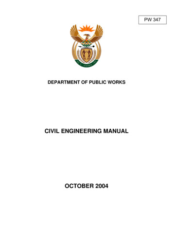
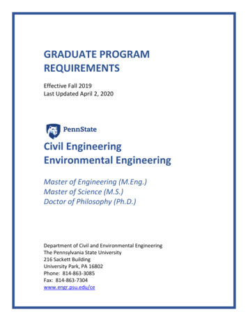
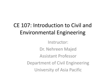
Course Materials- Civil Engineering- Steel Structuresstructures in public buildings, railway stations and bridges, which testifies the growth of steelin the past. The “Rabindra Sethu" Howrah Bridge in Calcutta stands testimony to a marvel insteel. Even after its service life, Howrah Bridge today stands as a monument. The recentexample is the Second Hooghly cable stayed bridge at Calcutta, which involves 13,200tonnes of steel. Similarly the Jogighopa rail-cum-road bridge across the river Brahmaputra isan example of steel intensive construction, which used 20,000 tonnes of steel. There arenumerous bridges, especially for railways built, exclusively using steel.As far as production of steel in India is concerned, as early as in 1907, Jamsetji NusserwanjiTata set up the first steel manufacturing plant at Jamshedpur. Also at the same time in 1905,Tata Institute for research and development works was established in Bangalore, Karnatakawhich was later renamed as Indian Institute of Science, Bangalore. Later Pandit JawaharlalNehru realised the potential for the usage of steel in India and authorised the setting up ofmajor steel plants at Bhilai, Rourkela and Durgapur in the first two five year plans. InKarnataka Sir Mokshakundam Visweswarayya established the Bhadravati Steel Plant. Theannual production of steel in 1999-2000 has touched about 25 million tonnes and this isslated to grow at a faster rate.1.2 Stress-strain Behaviour of SteelThe primary characteristics of structural steel include mechanical and chemical properties,metallurgical structures and weldability. In the past structural engineers have tended to focusonly on the tensile properties (longitudinal yield stress and ultimate tensile strength), withsome attention paid to the deformability as measured by the elongation at fracture of atension specimen. Since the modulus of elasticity, E, is constant for all practical purposes forall grades of steel, it has rarely been a consideration other than for serviceability issues.Weldability was assumed to be adequate for all such steels. Deformability or ductility wassimilarly assumed to be satisfactory, in part because the design specification has offered onlyvery limited, specific requirements.The stress-strain curve for steel is generally obtained from tensile test on standardspecimens as shown in Fig.1.1. The details of the specimen and the method of testing iselaborated in IS: 1608 (1995). The important parameters are the gauge length ‘Lc’ and theinitial cross section area So. The loads are applied through the threaded or shouldered ends.The initial gauge length is taken as 5.65 (So)1/2 in the case of rectangular specimen and it isfive times the diameter in the case of circular specimen. A typical stress-strain curve of thetensile test coupon is shown in Fig.1.2 in which a sharp change in yield point followed byplastic strain is observed. When the specimen undergoes deformation after yielding, Luder’slines or Luder’s bands are observed on the surface of the specimen as shown in Fig.1.3.These bands represent the region, which has deformed plastically and as the load isincreased, they extend to the full gauge length. This occurs over the Luder’s strain of 1 to 2%for structural mild steel. After a certain amount of the plastic deformation of the material, dueto reorientation of the crystal structure an increase in load is observed with increase in strain.This range is called the strain hardening range. After a little increase in load, the specimeneventually fractures. After the failure it is seen that the fractured surface of the two piecesform a cup and cone arrangement. This cup and cone fracture is considered to be anindication of ductile fracture. It is seen from Fig.1.2 that the elastic strain is up to εy followedby a yield plateau between strains εy and εsh and a strain hardening range start at εsh and thespecimen fail at εult where εy, εsh and εult are the strains at onset of yielding, strainUnder revision *, Funded by ETET Odisha10
Course Materials- Civil Engineering- Steel Structureshardening and failure respectively. Depending on the steel used, εsh generally varies between5 to 15 εy, with an average value of 10 εy typically used in many applications. For allstructural steels, the modulus of elasticity can be taken as 205,000 MPa and the tangentmodus at the onset of strain hardening is roughly 1/30th of that value or approximately 6700MPa.Figure 1.1 Standard steel specimenFigure 1.2 Stress-strain curve for sharp yielding structural steelsFigure 1.3 Luder’s band in steel specimensUnder revision *, Funded by ETET Odisha11
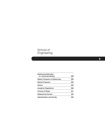
Course Materials- Civil Engineering- Steel StructuresFigure 1.4 Stress strain curve for continuously yielding structural steelsFigure 1.5 Tensile steel specimens before ruptureCertain steels, due to their specific microstructure, do not show a sharp yield point butrather they yield continuously as shown in Fig. 1.4. For such steels the yield stress is alwaystaken as the stress at which a line at 0.2% strain, parallel to the elastic portion, intercepts thestress strain curve. This is shown in Fig. 1.4. A schematic diagram of the tensile coupon atfailure is shown in Fig.1.5. It is seen that approximately at the mid section the area is ‘S’compared to original area S0. Since S is the actual area experiencing the strain, the true stressis given by ft P/S, where P is the load.However S is very difficult to evaluate compared to S0 and the nominal stress or theengineering stress is given by fn P/ S0 . Similarly, the engineering strain is taken as theratio of the change in length to original length. However the true strain is obtained wheninstantaneous strain is integrated over the whole of the elongation, given by(1.1)By suitable manipulation it could be shown thatUnder revision *, Funded by ETET Odisha12
Course Materials- Civil Engineering- Steel Structures(1.2)and similarly(1.3)where ft and fn are the true and nominal stresses respectively and εt and εn are the true andnominal strains respectively.1.3 Experimental Investigation of a True Stress-True Strain ModelIn this section, experimental investigation of a true stress-true strain model is described. Astandard uniaxial tensile test, in general, provides the basic mechanical properties of steelrequired by a structural designer; thus, the mill certificates provide properties such as yieldstrength Fy , ultimate strength Fu, and strain at fracture εf . The stress parameters areestablished using the original cross-section area of the specimen, and the average strainwithin the gauge length is established using the original gauge length. Because of the use oforiginal dimensions in engineering stress-strain calculations, such relations will always showan elastic range, strain hardening range, and a strain softening range. As the load increasesand when the specimen begins to fail, the cross-section area at the failure location reducesdrastically, which is known as the “necking” of the section. In general, the strain softening isassociated with the necking range of the test. Once the specimen begins to neck, thedistribution of stresses and strains become complex and the magnitude of such quantitiesbecome difficult to establish. Owing to the non-uniform stress strain distributions existing atthe neck for high levels of axial deformation, it has long been recognized that the changes inthe geometric dimensions of the specimen need to be considered in order to properly describethe material response during the whole deformation process up to the fracture. The truestress-true strain relationship is based on the instantaneous geometric dimensions of the testspecimen. Figure 1.6 illustrates the engineering stress-strain relationship and the true stresstrue strain relationships for structural steels. These relationships can be divided into fivedifferent regions as follows.Region-I (Linear Elastic Range). During the initial stages of loading, stress varies linearlyproportional to strain (up to a proportional limit). The proportional limit stress Fpl is typicallyestablished by means of 0.01% strain offset method. Thus, the engineering stress can berelated to engineering strain as follows: Fe Eεe in the range Fe Fpl and εe εpl, where Eis the initial elastic modulus of steel, which is often taken as 200,000MPa. The correspondingtrue stress and the true strain, which recognize the deformed geometrics of the section duringtests, can be established directly from the engineering stress and the engineering strain basedon the concept of uniform stress, small dimensional change, and In compressible material,which is valid for steel. Resulting relations are Ft Fe (1 εe) and εt ln(1 εe), where Ftand Fe are the true stress and engineering stress and εt and εe are the true strain and theengineering strain
Steel Bridge Design Handbook, Structural Behaviour of Steel, US Department of Transportation, November 2012 37. IS 7216-1974 (Reaffirmed 2006) Indian Standard Tolerances for fabrication of steel structures, pp. 1-27. Course Materials- Civil Engineering- Steel