Transcription
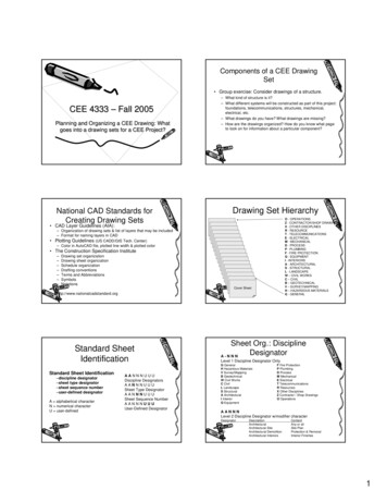
Components of a CEE DrawingSet Group exercise: Consider drawings of a structure.CEE 4333 – Fall 2005Planning and Organizing a CEE Drawing: Whatgoes into a drawing sets for a CEE Project?National CAD Standards forCreating Drawing Sets– What kind of structure is it?– What different systems will be constructed as part of this project:foundations, telecommunications, structures, mechanical,electrical, etc.– What drawings do you have? What drawings are missing?– How are the drawings organized? How do you know what pageto look on for information about a particular component?Drawing Set HierarchyO - OPERATIONSZ - CONTRACTOR/SHOP DRAWINGSX - OTHER DISCIPLINESR - RESOURCET - TELECOMMUNICATIONSE - ELECTRICALM - MECHANICALD - PROCESSP - PLUMBINGF - FIRE PROTECTIONQ - EQUIPMENTI - INTERIORSA - ARCHITECTURALS - STRUCTURALL - LANDSCAPEW – CIVIL WORKSC – CIVILB – GEOTECHNICALV – SURVEY/MAPPINGH – HAZARDOUS MATERIALSG - GENERAL CAD Layer Guidelines (AIA):– Organization of drawing sets & list of layers that may be included– Format for naming layers in CAD Plotting Guidelines (US CADD/GIS Tech. Center)– Color in AutoCAD file, plotted line width & plotted color The Construction Specification Institute–––––––Drawing set organizationDrawing sheet organizationSchedule organizationDrafting conventionsTerms and AbbreviationsSymbolsNotationsCover Sheethttp://www.nationalcadstandard.orgStandard SheetIdentificationStandard Sheet Identification–discipline designator–sheet type designator–sheet sequence number–user-defined designatorA alphabetical characterN numerical characterU user-definedAANNNUUUDiscipline DesignatorsAANNNUUUSheet Type DesignatorAANNNUUUSheet Sequence NumberAANNNUUUUser-Defined DesignatorSheet Org.: DisciplineDesignatorA-NNNLevel 1 Discipline Designator OnlyG GeneralH Hazardous MaterialsV Survey/MappingB GeotechnicalW Civil WorksC CivilL LandscapeS StructuralA ArchitecturalI InteriorQ EquipmentF Fire ProtectionP PlumbingD ProcessM MechanicalE ElectricalT TelecommunicationsR ResourcesX Other DisciplinesZ Contractor / Shop DrawingsO OperationsAANNNLevel 2 Discipline Designator w/modifier Architectural SiteArchitectural DemolitionArchitectural InteriorsContentAny or allSite PlanProtection & RemovalInterior Finishes1
Sheet Org.: Sheet TypeDesignatorAANNNSheet Org.: Sheet SequenceNumberAANNN0123456789The sheet sequence number identifies each sheet in a series ofthe same discipline and sheet type.General (symbols legend, notes, etc.)Plans (horizontal views)Elevations (vertical views)Sections (sectional views)Large Scale Views (plans, elevations, sections)DetailsSchedules and DiagramsUser DefinedUser Defined3D Representations (isometrics, perspectives, photographs)The first sheet of each series is numbered 01, followed by 02through 99.Sample Typical DrawingSetSheet Org.: ples - Supplemental DrawingsA - 1 0 2 R 1 (partially revised floor plan)A - 1 0 2 X 1 (totally revised floor plan)A - 1 0 2 A 1 (Phase 1 of a sequenced constructionfloor plan)Sheet TitleCover SheetNotes and SymbolsFloor PlanReflected Ceiling PlanRoof PlanExterior ElevationsBuilding SectionsWall SectionsEnlarged Toilet PlanDetailsRoom Finish ScheduleDoor & Window SchedulesDrawing Set ConsistencyUDS establishes organization andprovides consistency among disciplines.Thus, a floor plan may be located andidentified as:S - 101 Structural First Floor PlanA - 101 Architectural First Floor PlanM - 101 Mechanical First Floor PlanE - 101 Electrical First Floor PlanCAD Layer Name: DisciplineDesignatorAIA CAD Layer GuidelinesAI- W A L L-F U L L- DI M S- NAA - Level 1 Discipline DesignatorAI- W A L L-F U L LDiscipline DesignatorMajor GroupMinor Group 1Minor Group 2Status- DI M S- NAs forDrawingNumberingG GeneralH Hazardous MaterialsV Survey/MappingB GeotechnicalW Civil WorksC CivilL LandscapeS StructuralA ArchitecturalI InteriorQ EquipmentF Fire ProtectionP PlumbingD ProcessM MechanicalE ElectricalT TelecommunicationsR ResourcesX Other DisciplinesZ Contractor / Shop DrawingsO OperationsAA - Level 2 - modifier Architectural SiteArchitectural Demo.Architectural InteriorsContentAny or allSite PlanProtection & RemovalInterior Finishes2
CAD Layer Name: Major GroupAI- W A L L-F U L L- DI M SCAD Layer Name: Minor Groups- NAI- W A L L-F U L L- DI M S- NThe mandatory Major Group field is a four-character field that identifies a major buildingsystem. The prescribed Major Group field codes (four-character abbreviations) show on theLayer List are logically grouped with specific discipline designators. However, any MajorGroup may be combined with any prescribed Discipline Designator, provided that thedefinition of the Major Group remains unchanged. User-defined Major Group field codes arenot permitted.The optional Minor Group fields are four-character fields that provide further clarification ofinformation contained on a layer. The prescribed Minor Group field codes (four-characterabbreviations) show on the Layer List are logically grouped with specific disciplinedesignators. However, any Major Group may be combined with any prescribed DisciplineDesignator, provided that the definition of the Major Group remains unchanged. User-definedMinor Group field codes are permitted.Examples:Examples:V* - BLDG - DECKV* - POWR - MHOLB* - BORE - FDTAC* - DRIV - FLNE - SIGNS* - BEAM - STELS* - FNDN - PIERA* - DOOR - FULLAI – WALL - FIREOrganizing DrawingInformationCAD Layer Name: Status- NThe optional Status field is a one-character field that distinguishes the data contained on thelayer according to the status of the work or the construction phase. The prescribed fieldcodes are as follows:NEDFTMX1-9New workExisting to remainExisting to demolishFuture workTemporary workItems to be movedNot in contractPhase numbersIdentifying Spaces, ObjectsComponents Structure for identifying spaces, objects,components Reference Symbols Notes– General– Reference Keynotes– Sheet KeynotesMultiple Views – The CEE Perspective123456789159'-103"48 BAYS AT 18'-9" 150'-0"DB5TWO-WAYSLAB, TYP.18" X 18" INTERIORCONCRETE COLUMN,TYPICALC182-" THICK CONCRETE SLABBAD5A5TYPICAL FLOOR FRAMING PLAN14" X 20" EXTERIORCONCRETE COLUMN,TYPICALN1234567893"159'-1048 BAYS AT 18'-9" 150'-0"1-" COMPRESSIBLE JOINTMATERIAL, TYPICALC58-" BRICK WALLBELOWDB5TWO-WAYSLAB, TYP.18" X 18" INTERIORCONCRETE COLUMN,TYPICAL20'-1"I M SC10-" THICK CONCRETE SLAB62'-8"- D20'-10"F U L LB20'-1"-"- W A L L20'-1"I62'-8"ASurveying / mapping – buildings - outdoor decksSurveying / mapping – power - manholesGeotechnical – borings – field dataCivil – driveways – fire lane – pavement markingsStructural – beams - steelStructural – foundations – drilled piersArchitectural – doors – full heightArchitectural Interior – walls – fire wall20'-10"Surveying / mapping – buildings and primary structuresSurveying / mapping – powerGeotechnical - boringsCivil – drivewaysStructural – beamsStructural – foundationsArchitectural – doorsArchitectural Interior – walls20'-1"V* - BLDG - *V* - POWR - *B* - BORE - *C* - DRIV - *S* - BEAM - *S* - FNDN - *A* - DOOR - *AI – WALL - *AD5A5SECOND FLOOR FRAMING PLAN14" X 20" EXTERIORCONCRETE COLUMN,TYPICALN3
Reference SymbolsMultiple Views – The CEE Perspective1003"8'-949'-1114"1212348'-934"5630"3RD FLOOR2ND FLOOR8"1ST FLOOR1"14'-888'-812"4TH FLOOR3RD FLOOR2ND FLOORCEMENTPLASTER1ST FLOOR8'-812"8'-812""8'-812"5TH FLOOR14" TYP.PARTIAL BRICK WALL8-" BRICK WALLSOUTH PERIMETER FRAME ELEVATIONNORTH PERIMETER FRAME ELEVATIONDA20'-1"4TH FLOOR3RD FLOOR19'-7"12'-2"2ND FLOOR1ST FLOORD20'-1"7TH FLOOR6TH FLOOR5TH FLOOR139'-72"4TH FLOOR30'-11"3RD FLOOR122'-22"2ND FLOOR13'-6"1ST FLOOR20'-5"20'-1"8'-8"19'-6"ROOF14'-818"PENTHOUSE ROOF48'-4"580'-48"165'-82"157'-02"8'- 812"8'-812"8'- 812"C20'-10"8'-812"5TH FLOORCEMENT PLASTER8'-812"6TH FLOOR580'-48"165'-82"157'-02"8'-812"7TH FLOOR13'-6"ROOF8'-8"14'-818"19'-6"PENTHOUSE ROOF5'-1012"B20'-1"FRAME FORHOTEL -10"WEST PERIMETER FRAME ELEVATIONEAST PERIMETER FRAME ELEVATIONReference Symbols: Examples fromSkilling Ward Magnusson BarkshireInc.Multiple Views – The CEE Perspective123456789159'-103"48 BAYS AT 18'-9" 150'-0"Detail PlanNumber IdentificationSheet Number"18" X 18" INTERIORCONCRETE COLUMN,TYPICALC182-" THICK CONCRETE SLAB62'-8"TWO-WAYSLAB, TYP.20'-1"DB5Building SectionLetter IdentificationSheet NumberB20'-1"Key Plan IndicatorLetter denotes BuildingSection or Elevation20'-10"20'-10"8'-812"B20'-1"7TH FLOORCEMENTPLASTER8'-8"ROOF6TH FLOOR8'-812"4TH 3'-314"CONCRETESPANDRELS1"65'-821" TYP.2225TH FLOOR8'-812"22"7TH FLOOR6TH "2'-412"13'-6"12'-312"PENTHOUSE ROOF3'-314"A9HORIZONTAL LINES FOR F.B. STRAPS EA. SIDE16 GA. STUDS FOR MOUNTING SIGNS3'-314"14" TYP.88 BAYS AT 18'-9" 150'HORIZONTAL LINES FOR F.B. STRAPS EA. SIDE16 GA. STUDS FOR MOUNTING SIGNS19'-6"71"65'-828 BAYS AT 18'-9" '-6"68'- ficationWall SectionSheetLetter NumberIdentificationTYPICAL FLOOR FRAMING PLAN14" X 20" EXTERIORCONCRETE COLUMN,TYPICALN1234Sheet NumberNew BuildingGrid567893"159'-1048 BAYS AT 18'-9" 150'-0"DetailLetterIdentificationSheetNumber1-" COMPRESSIBLE JOINTMATERIAL, TYPICALC58-" BRICK WALLBELOWDB5TWO-WAYSLAB, TYP.18" X 18" INTERIORCONCRETE COLUMN,TYPICAL20'-1"Remark IndicatorG – General NotesD – Demolition NotesR – Remodel NotesS – Site NotesA5C10-" THICK CONCRETE SLAB62'-8"cloud area ofrevisionD520'-10"Revision Indicator20'-1"BAD5Existing BuildingGridA5SECOND FLOOR FRAMING PLAN14" X 20" EXTERIORCONCRETE COLUMN,TYPICALN2'-6"9"1"1'-4"Lap 24 bar dia.for interior column;lap 36 bar dia. forexterior column,minimum 24" (typ.)10" SLABSection Views – The CEE Perspective1"2Drawing Roads2"3CONT. L 3 x 3 x 163"12" 12"max maxEXPANDABLE JOINT MATERIAL4 - #4 CONT."2" CLEAR1" CLEAR24"2"slope 1:6 max.13'-6"4"4 @ 3"8" BRICK4"1 - #4 CONT.2" clear (typ.)to vertical barDTYPICAL COLUMN DETAIL2" clear1'-4"TYP. FLOORROOF22"ROOF22"2ND FLOORTYP. FLOOR14"30"2ND FLOOR30"SECTION OF BRICK WALL1"2222"C2212"3" clear (typ.)41 - #4varies24" lap#4 @ 24" O.C.VERTICAL BARS4"2" clearBTYPICAL TRANSVERSE SPANDRELSATYPICAL LONGITUDINAL SPANDRELS4
Drawing RoadsDrawing Structural SteelComponentsDrawing RC StructuralComponentsNotesReference Keynotes:Masterformat for specifications (CSI)Reference KeynotesDivisionSpecificationDivision1General pment4Masonry12Furnishings5Metals13Special Construction6Wood and Plastics14Conveying Systems7Thermal and Moisture Protection15Mechanical8Doors and Windows16ElectricalSpecification5
Sheet Keynotes6
3 CAD Layer Name: Major Group A I - W A L L - F U L L - D I M S - N The mandatory Major Group field is a four-character field that identifies a major building system. The prescribed Major Group field codes (four-character abbreviations) show on the Layer List ar