Transcription
Pipette Cookbook 2018P-97 & P-1000 Micropipette PullersRev. F
The Pipette Cookbook was written, compiled and created by Adair Oesterle withSutter Instrument Company. A printed version of the Pipette Cookbook is includedwith all new P-97 and P-1000 Pullers and the pdf can found and downloadedfor free through the Sutter web site.http://www.sutter.com/contact/faqs/pipette cookbook.pdfRevised and expanded versions of the Pipette Cookbook are released every two tothree years. Please contact Sutter if you have any recommendations,comments and/or corrections to offer.We welcome your feedback!Adair Oesterle at the Getty Museum – not pulling pipettes!Sutter Instrument CompanyOne Digital DriveNovato, CA 94949415-883-0128www.sutter.com2
TABLE OF CONTENTSIntroduction . . . . . . . . . . . . . . . . . . . . . . . . . . . . . . . . . . . . . . . . . . . . . . . . . . . . . . . . . . . . Pg. 5-6Using the Pipette Cookbook with the P-87, P-80/PC & P-1000 . . . . . . . . . . . . . . . . . . . Pg. 6Sutter Capillary Glass . . . . . . . . . . . . . . . . . . . . . . . . . . . . . . . . . . . . . . . . . . . . . . . . . . . . Pg. 7Sutter Filaments . . . . . . . . . . . . . . . . . . . . . . . . . . . . . . . . . . . . . . . . . . . . . . . . . . . . . . . . Pg. 8Ingredients . . . . . . . . . . . . . . . . . . . . . . . . . . . . . . . . . . . . . . . . . . . . . . . . . . . . . . . . . . . . Pg. 9Parameter Settings Defined . . . . . . . . . . . . . . . . . . . . . . . . . . . . . . . . . . . . . . . . . . . . . . . Pg. 10General Guideline for Parameter Settings . . . . . . . . . . . . . . . . . . . . . . . . . . . . . . . . . . . Pg. 11Ramp Test . . . . . . . . . . . . . . . . . . . . . . . . . . . . . . . . . . . . . . . . . . . . . . . . . . . . . . . . . . . . Pg. 12Installing a Filament - Step-by-Step . . . . . . . . . . . . . . . . . . . . . . . . . . . . . . . . . . . . . . . . Pg. 13-18Centering Filament Over Air Jet . . . . . . . . . . . . . . . . . . . . . . . . . . . . . . . . . . . . . . . . . . . Pg. 17-18Chapter 1Electrophysiology Overview . . . . . . . . . . . . . . . . . . . . . . . . . . . . . . . . . . Pg. 19Extracellular Recording Electrodes . . . . . . . . . . . . . . . . . . . . . . . . . . . . . Pg. 20Intracellular Recording Electrodes . . . . . . . . . . . . . . . . . . . . . . . . . . . . . . Pg. 21-22Additional Concerns about Intracellular Recording . . . . . . . . . . . . . . . . Pg. 23-26Patch Pipettes . . . . . . . . . . . . . . . . . . . . . . . . . . . . . . . . . . . . . . . . . . . . . . Pg. 27-34Pre-Heat Mode . . . . . . . . . . . . . . . . . . . . . . . . . . . . . . . . . . . . . . . . . . . . . Pg. 29Writing a Stable Patch Program . . . . . . . . . . . . . . . . . . . . . . . . . . . . . . . . Pg. 30-32Cheet Sheet – Parameter Adjustment Guide . . . . . . . . . . . . . . . . . . . . . . Pg. 33Chapter 2Adherent Cell, C.elegans, & Drosophila. . . . . . . . . . . . . . . . . . . . . . . . . . Pg. 35-36XenoWorks Digital Injector Settings . . . . . . . . . . . . . . . . . . . . . . . . . . . . Pg. 37-38Pre-Pulled Injection Pipettes – Do You Know What You Are Buying? . . . . Pg. 39-40Zebrafish Embryo Injection . . . . . . . . . . . . . . . . . . . . . . . . . . . . . . . . . . . . Pg. 41-42Chapter 3Bee-Stinger Needle . . . . . . . . . . . . . . . . . . . . . . . . . . . . . . . . . . . . . . . . . . Pg. 43-44Chapter 4Pronuclear Injection . . . . . . . . . . . . . . . . . . . . . . . . . . . . . . . . . . . . . . . . . Pg. 45-48Chapter 5Embryonic Stem Cell Injection (ES Cell) . . . . . . . . . . . . . . . . . . . . . . . . . Pg. 49-50Chapter 6Intracytoplasmic Sperm Injection (ICSI) . . . . . . . . . . . . . . . . . . . . . . . . . Pg. 51-52Chapter 7Nuclear Transfer (NT) . . . . . . . . . . . . . . . . . . . . . . . . . . . . . . . . . . . . . . . . Pg. 53-54Chapter 8Holding Pipettes . . . . . . . . . . . . . . . . . . . . . . . . . . . . . . . . . . . . . . . . . . . . Pg. 55-56Chapter 9Xenopus Oocyte Injection . . . . . . . . . . . . . . . . . . . . . . . . . . . . . . . . . . . . . Pg. 57-583
Chapter 10Large Pipettes, 20µ to 200µ Tips, Methods on Breaking Back Tip,Glass-on-Glass Technique & Using the Ceramic Tile (CTS) . . . . . . . . . . Pg. 59-62Chapter 11Aspiration Pipettes: Cell Selection, Cell Transfer,Single Cell Mechanics & Blastomere Biopsy. . . . . . . . . . . . . . . . . . . . . . Pg. 63-64Chapter 12Aluminosilicate Glass and Custom Programs. . . . . . . . . . . . . . . . . . . . . . Pg. 65-68Chapter 13ZIKA Research and Mosquito Egg Injections . . . . . . . . . . . . . . . . . . . . . Pg. 69-73Chapter 14Crazy Lab Lore . . . . . . . . . . . . . . . . . . . . . . . . . . . . . . . . . . . . . . . . . . . . . Pg. 75-81Chapter 15Variability and “The 15 Questions”. . . . . . . . . . . . . . . . . . . . . . . . . . . . . . Pg. 83-84Chapter 16Installation of Box or Trough Filament - Review . . . . . . . . . . . . . . . . . . . Pg. 85-87Eccentric Adjustments . . . . . . . . . . . . . . . . . . . . . . . . . . . . . . . . . . . . . . . . Pg. 88Chapter 17Filamented Glass . . . . . . . . . . . . . . . . . . . . . . . . . . . . . . . . . . . . . . . . . . . . Pg. 89Chapter 18XenoWorks Microinjection System. . . . . . . . . . . . . . . . . . . . . . . . . . . . . . Pg. 91-93Chapter 19BV-10 Beveler . . . . . . . . . . . . . . . . . . . . . . . . . . . . . . . . . . . . . . . . . . . . . . Pg. 95-96GENERAL LOOK UP TABLESType A, B, C, D, & E Programs . . . . . . . . . . . . . . . . . . . . . . . . . . . . . . . . . . . . . . . . . Pg. 97General Look Up Tables . . . . . . . . . . . . . . . . . . . . . . . . . . . . . . . . . . . . . . . . . . . . . . . . . . Pg. 98-105Notes . . . . . . . . . . . . . . . . . . . . . . . . . . . . . . . . . . . . . . . . . . . . . . . . . . . . . . . . . . . . . . . . . Pg. 106-108P-97 Pipette Puller*New* P-1000 Pipette Puller*The New P-1000 Pipette Puller has the “Pipette Cookbook” programs incorporated into its memory.The new Cookbook feature for the P-1000 can be used to look up and install a majority of theprograms found in this text. By selecting the filament type, glass dimension, and application youcan install a pre-written program. To fine-tune the program you installed from the cookbook directory,please refer to pg 11 for instructions on how to adjust the parameter settings.4
IntroductionThe Sutter Instrument Pipette Cookbook is organized according to application and describes the requiredpipette needed for that application. While we have attempted to cover a wide range of applications and typesof pipettes, it is possible we have yet to include what you might be looking for. Additional applications areoccasionally added to new revisions of the cookbook and if you have suggestions for future revisions,please contact Sutter Instrument Company.At the beginning of each chapter you will find a general discussion of each application and a detaileddescription of the morphology of the pipette (taper length, tips size, resistance, etc) needed for yourapplication. In each chapter we provide the “ideal” combination of glass size (outer and inner diameters)and filament type for your application, along with the recommended parameter settings with which tostart. We then provide suggestions on how to adjust and “tweak” the recommended parameter settingsin case you need to modify the morphology of the resulting pipette. When applicable, we havealso provided information on the XenoWorks microinjection equipment, the set up and the settings thatwould be required for that application.The “ideal” filament and glass combination, and the associated recommended parameter settings wehave provided in each chapter have been established over years of experience, and are a result of in-depthresearch results and customer feedback. If you are unable to match the filament and glass combinationthat is provided for a specific application or you lack the “recommended ingredients,” you can refer tothe “General Look Up Tables” to find an alternate program. The General Look Up Tables are organizedaccording to the type of filament installed in your puller and the dimension of glass (OD and ID). Programsare listed in the Tables as Type A, B, C, D, and E. Each “Type” classification is explained on page 97.It is important to keep in mind that what is provided in the General Look Up Tables might not be “ideal”for your application. There are some combinations of filament and glass that do not work well for a givenapplication and can create very unstable results. So, we would like to emphasize again that what has beenprovided in each chapter is the best approach we have come to recognize.The most common sources of difficulty in producing the right shape of pipette can be attributed to theuse of poor parameter settings. Just one poorly adjusted parameter setting in the program - too high ortoo low - can lead to a lot of variability in tip size, taper length and resistance. These very high or lowsettings can be seen as “bad ingredients” in your recipe. For a general guideline on the parametersettings and the range of values we recommend, please refer to page 11. If you stay within the suggestedrange for each parameter, it will be less likely that you will “get lost” or off track when trying to write aprogram or adjust your settings. It is possible that the not-so-ideal parameter settings were established in asomewhat haphazard manner by various well-intentioned researchers who are possiblyno longer in the lab. It is also conceivable that the program one is using had been adopted from someonewho had a different model of Sutter puller and/or a different combination of filament and glass.Please be aware that simply using a program recommended by someone else can often lead toundesirable tip sizes, and in worse cases, the unfortunate event of burning out your filament. If youhave acquired your settings from someone outside of Sutter, it is best to run a ramp test to make sure theheat settings you have been advised to use will not damage or burn out your filament. Information aboutthe Ramp Test can be found on page 12.5
If a program in this Cookbook does not produce the proper pipette, this might be a result of a pooralignment or mechanical adjustment on your puller. It is important to make sure your puller is in goodworking order. Be sure to check that the filament is perfectly centered over the air jet, the air jet is set2 to 3mm below the base of the filament, the glass capillary is properly positioned within the filament,and the filament shape is correct. If you find that the program provided and the suggested changes to theparameter settings do not produce good results, please refer to page 11, “General Guideline forParameter Settings” and Chapter 15, “Variability.” If you feel your puller might be in need of a tune upor repair, please contact Sutter Instrument and inquire about having your puller refurbished.Using the Pipette Cookbook with a P-87 or a P-80/PCTo adapt the P-97/P-1000 Pipette Cookbook programs to an earlier model Sutter Micropipette Puller,including the P-87 and P-80/PC, please do the following:§If you have a P- 87, reduce the heat setting listed in the chart by 5-10 units. The power available tothe filament in the P-97 is 25% higher than the P-87 and the rate of current increase during a ramptest on the P-97 is more gradual. These differences require one to alter the heat setting when usinga P-97 program on a P-87. If a Delay Value is provided, you will need to install a Time Valuebetween 175 and 250 in place of the Delay Value.§If you have a P-80/PC, reduce the heat setting listed in the table by 10 units. The Time Mode on theP-80/PC functions just like the Delay Mode on the P-97 and P-1000. If a Delay Value is provided inPipette Cookbook program, install this same number as the Time Value on your P-80/PC. If a TimeValue is provided in the Pipette Cookbook program, please install a Time Value between50 to 110 on the P-80/PC.§The Pressure of the out-going regulator of the P-80/PC should be set to 50psi. The airflowof the Nitrogen is controlled by adjusting the valve opening of the air solenoid, which is avertical micrometer dial behind the left puller bar. Micrometer settings between 1 and 1.25are recommended.* For detailed information about the cooling modes, Time & Delay, please refer to your P-97or P-1000 manual.Using the Pipette Cookbook with a P-1000The New P-1000 Pipette Puller has the “Pipette Cookbook” programs incorporated into its memory.The new Cookbook feature for the P-1000 can be used to look up and install a majority of the programsfound in this text. By selecting the filament type, glass dimension, and application you can find and installa pre-written program. To fine tune your program, please refer to page 11 for instructions on how to adjustthe parameter settings. Aluminosilicate programs and Type E programs were not incorporated into theP-1000. Programs for pulling Aluminosilicate glass can be found in Chapter 12. You might also want totry using the new Pre-Heat Feature on your P-1000 puller to help stabilize your programs. For additionaladvice, please contact Sutter Technical Support.6
SUTTER CAPILLARY GLASSStandard Wall Borosilicate Tubing (With Filament)Catalog 10BF200-116-15Outside 1.50mm1.50mm1.50mm1.50mm2.00mm2.00mm2.00mmInside DiameterOverall ces per tandard Wall Borosilicate Tubing (No Filament)Catalog 0-116-10B200-116-15Outside 1.50mm1.50mm2.00mm2.00mmInside 0.86mm0.86mm1.16mm1.16mmOverall mPieces per Package225225250250250250250250250250250Thin Wall Borosilicate Tubing (With Filament)Catalog F165-120-10BF200-156-10BF200-156-15Outside 1.50mm1.65mm2.00mm2.00mmInside 1.17mm1.20mm1.56mm1.56mmOverall mPieces per Package250250250250250225250100250250100Thin Wall Borosilicate Tubing (No Filament)Catalog 50-110-10Outside Diameter1.00mm1.00mm1.20mm1.50mm1.50mmInside Diameter0.75mm0.75mm0.90mm1.10mm1.10mmOverall Length10cm15cm10cm7.5cm10cmPieces per Package225225225225225For a list of our Aluminosilicate & Multibarrel Borosilicate Glass, please refer to our web site (www.sutter.com)7
Filaments & AccessoriesBox FilamentsP-1000, P-97, P-87, P80PC, P80C, PC-84, P-77BFB215B 2.0mm square box filament, 1.5mm wide .FB220B 2.0mm square box filament, 2.0mm wide .FB230B 2.0mm square box filament, 3.0mm wide .FB255B 2.5mm square box filament, 2.5mm wide .FB245B 2.5mm square box filament, 4.5mm wide .FB315B 3.0mm square box filament, 1.5mm wide .FB320B 3.0mm square box filament, 2.0mm wide .FB330B 3.0mm square box filament, 3.0mm wide .Trough FilamentsP-1000, P-97, P-87, P80PC, P80C, PC-84, P-77BFT315B 1.5mm wide trough filament .FT320B 2.0mm wide trough filament .FT330B 3.0mm wide trough filament .FT345B 4.5mm wide trough filament .AccessoriesBX-10: Pipette Storage Box (Holds 10 pipettes) .BX-20: Pipette Storage Box (Holds 20 pipettes) .Custom Filament: Custom platinum/iridium filament .FPS Fire polishing spacer for P97, P87, and P2000 pullers .FS1875 Platinum/iridium sheet, 18mm x 75mm x 0.05mm (0.002in) .CTS Ceramic tile for scoring glass (large tips 20 to 200 microns) .IMOXAB Instruction manual (specify product when ordering) .Pipette Storage BoxesItem# BX10 or BX20Sutter Capillary GlassPage 7 for Parts NumbersCeramic Tiles (See Chapter 10)Item # CTS8
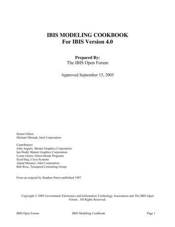
THREE MAIN INGREDIENTS: GLASS FILAMENT TYPE & SIZE (Heating Element)2.5mm x 2.5mm Box Filament Box Filament Centered Over Air JetPARAMETER SETTINGS PROGRAMHEATRamp 10PULL60-90VEL80DEL90PRESSURE200GLASSWithin each Chapter describing a specific application, Slice Patch Recording for example, a specific glasstype, a specific wall thickness, and filamented or non-filamented glass is recommended. Quartz glass is notdiscussed much in this cookbook because the filament-based pullers like the P-97 and P-1000 cannot meltQuartz glass, but it is mentioned (and recommended if you have a P-2000 Puller) in Chapter 13 – ZikaResearch and Mosquito Egg Injections. More information on the glass can be found inChapter 14– Crazy Lab Lore.FILAMENTSThe filament in your puller is the heating element used to melt the glass. The filaments come in two basicshapes, box or trough. See page 8 for list of filaments. They also come in various widths and IDs (innerdiameter or opening of the box or trough). The filament is made of Platinum:Iridium (90:10) and the properheat setting to use for your filament is determined by running a RAMP TEST. The ramp test is furtherdiscussed on page 12.9
PARAMETER SETTINGSThe P-97 and P-1000 puller use the following parameters to control the melting and pulling of the glass:Each application described in the Pipette Cookbook will offer a starting program where the heat, pull,velocity, time/delay and pressure settings are suggested. Please see the SutterInstrument YouTube Channelto find the Scientists Empowering Scientists Webinar, “How to Make Better Pipettes”, which describes theparameters settings in more depth. The manual that came with your puller will also have a description of theparameter settings. A brief description of each setting is discussed below:HEAT – This is the amount of current supplied to the filament. The value does not represent thetemperature, but indicates how much current is delivered to the filament. The filament needs to gethot enough to melt the glass, and this heat value is dependent on the filament shape, the filament sizeand the size and wall thickness of the glass. If you use a heat setting that is too high or too low, yourisk burning out the filament or damaging the puller. So it is not a good idea to guess at the heatsetting. You can also introduce a lot of variability if the heat setting is not ideal. To determine theproper and safe HEAT value to use, one should run a RAMP TEST. For more information about theRamp TEST, see page 12.PULL – This is the hard pull introduced to the glass after the glass has softened.This pull value determines the amount of current supplied to the pull solenoid to create the hard pull.The puller can pull the glass out with a hard pull (Pull 0 ) where the puller only uses thegravitational weight of the plunger inside the puller to pull on the glass. A pull of 0 is typicalwhen pulling a patch pipette where you want a 3-5mm short taper and a 1-3µm tip. A pull of 50-150is typical when making a sharp electrode of 30 to100 MΩ or when making a microinjection needle.VELOCITY – This is the rate of separation of the puller bars when the glass first starts to melt. Thevelocity is detected by a transducer inside the puller, a patented feature, and the velocity has a directcorrelation to the viscosity of the glass. The velocity is the “trip point” for turning off the heat andstarting the cooling and the hard pull. When the velocity is low, the pipette taper will be shorter.When the velocity value is low enough, as when pulling a patch pipette, the puller will pull inmultiple cycles or “LOOPS”. A velocity of 18 - 65 is typical when pulling a patch pipette, and whenusing a one-line program, the lower the velocity is, the more times the program will loop.LOOPING is further discussed on page 29. A pull of 50-150 is typical when making a sharpelectrode of 30 to100 MΩ or when making a microinjection needle.TIME – This is the duration of air used to cool the glass and the filament as the glass is beingpulled. When using the Time mode, the glass softens, the velocity trip point is reached, and then theglass is cooled at pulled simultaneously. The duration of cooling is determined by the value of theTime where each unit of time is equivalent to 0.5 milliseconds of cooling air. Traditionally a Timeof 150 (75ms) is recommended when using a trough filament or when using thin walled glass andmaking a pipette for slice patch recording. A higher Time value of 250 (125ms) is recommendedwhen using a box filament and pulling thick walled glass.DELAY – This is the alternative mode of cooling which provides a longer duration of cooling(300ms) than the Time mode (max of 127.5ms). In the Delay mode, the glass softens, the velocitytrip point is reached, and then 300ms of cooling is initiated. The Delay value determines how longthe glass is cooled before the hard pull is engaged and continues cooling the glass as the glass ispulled. So by cooling the glass while delaying the hard pull, you can determine how viscous theglass is when it is being pulled. I find this to be a more sophisticated way of controlling the glasswhen making electrodes. A low Delay value of 40-90 units will expose the glass to less coolingbefore the hard pull, the glass will be more molten when the hard pull engages and this will result10
in a longer tapered pipette. A higher delay value of 100-250 will provide more cooling to the glassbefore the hard pull engages, the glass will be more viscous, and this will result in a shorter taperedpipette. The delay mode of cooling is also most often used when pulling patch pipettes to deliver alonger duration of cooling to the glass which helps produce shorter tapered patch pipettes. Asdemonstrated on pages 30 and 31, a Delay mode of 1 with a Pull value of 0 results in shorttapered pipettes.PRESSURE – This is the pressure of air used to cool the filament and the glass. The defaultPressure setting is 500 units, which represents 2psi of cooling air. Both the Time and Delay modes(duration of cooling) work in conjunction with the Pressure to cool the glass. The higher thePressure, the more robust the cooling is to the glass and filament. An increase in Pressure will coolthe glass faster and shorten the taper. A decrease in the Pressure will reduce the cooling to the glassand allow for longer and more gradual tapers.General Guideline for the Parameter SettingsWhen designing a program or adjusting your existing parameter settings, it is quite easy to endup “lost” and with very unstable settings if you do not know where to start or when a setting isconsidered too high or too low. If you are trying to design a program from scratch, please refer to the“cookbook” programs provided for various applications. There you will find what we hope proves tobe a good starting point. If you are in the midst of adjusting and fine-tuning your existing parametersettings, below is a general guideline suggesting the range of settings to stay within for eachparameter. These ranges are a general rule of thumb, and there could often be exceptionsdepending on the filament and glass combination, the OD and ID of glass you are using,and the final morphology of the pipette you are aiming for.HEAT:Ramp - 5 to Ramp 15 for most applications!PULL:030 -7070 - 150Patch, 3-5mm taper and 1-3µm tipsMicroinjection, 6-8mm tapers, 0.9 to 0.5µm tipsHigh MΩ, 9-15mm tapers, 0.5 to 0.06µm tipsVELOCITY:20 - 6050 - 8070 - 100Patch, 3-5mm taper and 1-3µm tipsMicroinjection, 6-8mm tapers, 0.9 to 0.5µm tipsHigh MΩ, 9-15mm tapers, 0.5 to 0.06µm tipsTIME:250 box, 150 trough Patch, 3-5mm taper and 1-3µm tips250 box, 150 trough Microinjection, 6-8mm tapers, 0.9 to 0.5µm tips250 box, 150 trough High MΩ, 9-15mm tapers, 0.5 to 0.06µm tipsDELAY:160 - 11040 - 90PRESSURE:200 - 500200 - 700Patch, 3-5mm taper and 1-3µm tipsMicroinjection, 6-8mm tapers, 0.9 to 0.5µm tipsHigh MΩ, 9-15mm tapers, 0.5 to 0.06µm tipsThin Walled GlassThick Walled Glass11
RAMP TESTTo choose an appropriate heat setting, you must first determine the amount of heat required to meltyour glass by running a RAMP TEST. The heat value established by the ramp test will depend on thetype of heating filament installed in your puller and the type and dimension of glass you are using.The ramp test value for a box filament will traditionally be 1.5 to 2 times higher than the value ofa trough filament.When to Run a Ramp Test§ Using the Puller for the First Time§ Whenever you Change the Filament§ Whenever you Change Glass§ Before Writing or Editing a ProgramHow to Run a Ramp Test on a P-97 (for the P-1000, press “Ramp” on upper right of display)§ Enter any program number 0-99 when using a P-97§ Press clear CLR to enter the control functions§ Press 0 to not clear all parameter values§ Press 1 to run a RAMP TEST§ Install glass and press PULL To interrupt the RAMP TEST or reset the display after a ramp test, press RESET When a ramp test is executed, the following events take place1. The puller increments the HEAT2. Once the HEAT output allows the glass to soften, the puller bars will drift apart3. When the factory-set ramp velocity is reached (trip-point) the heat is turned off4. The Ramp Test value will be shown on the displayExpected ramp test valuesFilament #Filament DimensionsExpected Ramp Test ValuesMaximum HeatFT330B3mm x 3mm TROUGH250 – 300 (see warning below)Ramp 20FB255B2.5mm x 2.5mm BOX 480 to 540Ramp 30FB330B3.0mm x 3.0mm BOX 550 to 650Ramp 40FB245B2.5mm x 4.5mm BOX 750 to 880Ramp 75* Warning - If the ramp test value for your trough filament is OVER 300 units, this might be too highand could indicate that the filament shape is poor and therefore inefficiently heating the glass.Please remove your filament and reshape it according to the instructions in Chapter 14.Recommended Heat Settings for Each Filament TypeFilamentRecommended Heat Setting3mm TROUGH2.5mm x 2.5mm BOX3.0mm x 3.0mm BOX2.5mm x 4.5mm BOXRamp 15RampRampRamp* Caution - If your Heat setting is greater than 20 to 50 units above the ramp value, dependingon the filament shape and size, (see above table), you will risk burning out the filament!12
“INSTALLING A FILAMENT” - STEP by STEPVideo Available on SutterInstrument YouTube ChannelInstalling a Filament - Step 1 of 11Remove the Humidity Control Chamber, loosen the filament clamp screwsand remove the old or damaged filament.Installing a Filament - Step 2 of 11Install a piece of glass in the right puller bar. Slide the glassto the left edge of the brass jaws and clamp the glass as depicted below.Installing a Filament - Step 3 of 11Before installing a trough filament, you must shape it.Use your fingers and needle-nose pliers to produce a good shape.13
Installing a Filament - Step 4 of 11Hold the filament as shown and install the filament so the glass runs through the center of the filament.Using your fingers will not damage the filament and any oils from your hands will burn off duringthe first ramp test.Installing a Filament - Step 5 of 11If replacing a trough with a box – move both jaws DOWN approximately 3mm each.If replacing a box with a trough – move both jaws UP approximately 3mm each.Loosen screw to move top jawLoosen screw to moving bottom jawInstalling a Filament - Step 6 of 11Use your glass as a tool. Hold the left end of the glass and bend it front to back to gently position thefilament front to back so it is centered around the glass. Then use the tip of a screw driver to nudge thefilament right/left to center it over the air jet (VERY IMPORTANT). See Page 1714
Installing a Filament - Step 7 of 11Once the filament is centered to the glass and to the air jet, place your finger on the brass clampbefore tightening the clamp screw. This prevents the filament from moving out of place whentightening the screw and will make your life easier.Trough Installation:BAD – not centered over air jetGOOD – centered over air jet ¢ered around glassBAD Shape – walls angled outwardGOOD Shape – walls angled inwardBox Installation: BAD & GOOD15
Installing a Filament - Step 8 of 11With the glass still in place, examine the alignment of the filament from above and horizontally.If the filament is not properly positioned, fix the alignment.For LARGE adjustments, repeat steps 4-7.For SMALL adjustments, use the filament block assembly eccentrics (seen below)ECCENTRIC ADJUSTMENTSLoosen locking screw, turn eccentric to adjust jaw assembly Up and Down then tighten locking screw[[Loosen locking screw, turn eccentric to adjust Front to Back, then tighten locking screwInstalling a Filament - Step 9 of 11Once the filament is properly installed, replace the humidity control chamber.Install a piece of glass making sure it does not hit either side of the chamber, or the filament.If the glass runs into the chamber or the filament, contact Sutter for additional instructions.Installing a Filament - Step 10 of 11Open an existing or new program.Bring the puller bars together.Clamp the glass and run a new Ramp Test.Any time you install a new filament, open a new vial of glass,change the alignment, position or shape of the filament, you must run a new ramp test.The Last Step! Check to make sure your filament is CENTERED over air jet. See pages 17 - 18.16
Centering Filament Over Air Jet – Step 11 of 11If your filament is not properly centered over the air jet (right to left), this will not only make onepipette longer than the other and the right an
Using the Pipette Cookbook with a P-87 or a P-80/PC To adapt the P-97/P-1000 Pipette Cookbook programs to an earlier model Sutter Micropipette Puller, including the P-87 and P-80/PC, please do the following: § If you have a P- 87, reduce the heat setting listed in the cha