Transcription
I'NASATP1316C. 1NASA Technical Paper 1316Wind-Tunnel Investigationat Supersonic Speeds ofa Canard-Controlled Missile WithFixed and Free-Rolling Tail FinsA. B. Blair, Jr.SEPTEMBER 1978NASA
,. .' II
TECH LIBRARY KAFB. NMIllllllSl0334438ll lllIlllII1lNASA Technical Paper 1316Wind-Tunnel Investigationat Supersonic Speeds ofa Canard-Controlled Missile WithFixed and Free-Rolling Tail FinsA. B. Blair, Jr.Langley Research C e t e rHamptozz, VirgiltiaNASANational Aeronauticsand Space AdministrationScientific and TechnicalInformation Office1978
r e f e r e n c e d i a m e t e r , 6.604c m (2.600 i n . )1r e f e r e n c e body l e n g t h , 99.060 c m (39.000 i n . )MMach number(Psf a )f r e e - s t r e a m dynamic p r e s s u r e , N/m2a n g l e o f a t t a c k , degdrolld i f f e r e n t i a l d e f l e c t i o n s of t w o c a n a r d s ( c a n a r d s 2 and 4, shown i ns k e t c h ( a ) ) for r o l l c o n t r o l ; i n d i v i d u a l c a n a r d s a r e d e f l e c t e di n d i c a t e d amount: n e g a t i v e to p r o v i d e c o u n t e r c l o c k w i s e r o t a t i o nwhen viewed from r e a r , degGyawy a w - c o n t r o l d e f l e c t i o n o f t w o c a n a r d s ( c a n a r d s 1 and 3 , shown i ns k e t c h ( a ) ) ; p o s i t i v e for l e a d i n g e d g e r i g h t when viewed from r e a r ,deg@Cm o d e l r o l l a n g l e ; p o s i t i v e clockwise when viewed from r e a r ( f o r@c Oo, c a n a r d s are i n v e r t i c a l and h o r i z o n t a l p l a n e s ) , degr o l l r a t e o f t a i l - f i n a f t e r b o d y ; p o s i t i v e c l o c k w i s e when viewed fromr e a r , rpms t a t i c l o n g i t u d i n a l s t a b i l i t y para.meterCanardsI3Rear v i e wSketch (a)3I
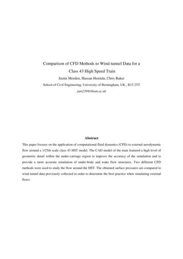
APPAKATUS AND TESTSWind TunnelThe investigation was conducted in the low Mach number test section of theLangley Unitary Plan wind tunnel, which is a variable-pressure, continuous-flowfacility, The test section is approximately 2.13 m ( 7 ft) long and 1 . 2 2 m( 4 ft) square* The nozzle leading to the test section is of the asymmetricsliding-block type, which permits a continuous variation in Mach number fromabout 1 . 5 to 2 . 9 .(See ref. 7 . )ModelDimensional details of the model are shown in figure 1 (a) and a modelphotograph is shown in figure 2. The model was a cruciform missile configuration that consisted of a cylindrical body with canards, aft tail fins, and aThe complete model body had a finetangent ogive nose of fineness ratio 3 . 0 .ness ratio of 1 5 . The canards and tail fins had slab cross sections withbeveled leading and trailing edges. In order for the model to have a freerolling tail-fin assembly, the tail-fin afterbody was mounted on a set of lowfriction ball bearings and was free to rotate through 3 6 0 0 (lock screw out).For the fixed-tail configuration (lock screw in), the tail fins were locked inline with the canards, For both the fixed and free-rolling tail configurations, the canards were deflected to provide roll control and yaw control.The tail fins were not deflected (zero cant angle) and the tail-fin assemblyhad no braking system.Test ConditionsTests were performed at the following tunnel conditions:Reynolds numberMachnumber1.702.1 178143015802056per meterper foot6.66.66.66.62.02.02.02.0xlo6x106The dewpoint temperature measured at stagnation pressure was maintainedbelow 2 3 9 K (-300 F) to assure negligible condensation effects. All testswere performed with boundary-layer transition strips measured streamwise onboth sides of the canards and tail fins and located 3.05 cm ( 1 . 2 0 in.) aft ofthe body nose and 1 . 0 2 cm ( 0 . 4 0 in.) aft of the leading edges. The transitionstrips were approximately 0 , 1 5 7 cm wide ( 0 . 0 6 2 in.) and were composed of No. 50sand grains sprinkled in acrylic plastic. (See ref. 8 . )4
Ir e f e r e n c e d i a m e t e r , 6.604 c m (2.600 i n . )c m (39.000 i n . )1r e f e r e n c e body l e n g t h , 99.060MMach number9f r e e - s t r e a m dynamic p r e s s u r e , N/m2(psfa)a n g l e o f a t t a c k , degd i f f e r e n t i a l d e f l e c t i o n s o f t w o c a n a r d s ( c a n a r d s 2 and 4 , shown i ns k e t c h ( a ) ) or r o l l c o n t r o l ; i n d i v i d u a l c a n a r d s a r e d e f l e c t e di n d i c a t e d amount; n e g a t i v e t o p r o v i d e c o u n t e r c l o c k w i s e r o t a t i o nwhen viewed from r e a r , deg&yawy a w - c o n t r o l d e f l e c t i o n o f t w o c a n a r d s ( c a n a r d s 1 and 3, shown i ns k e t c h ( a ) ) ; p o s i t i v e f o r l e a d i n g e d g e r i g h t when viewed from r e a r ,de9@Cmodel r o l l a n g l e ; p o s i t i v e clockwise when viewed from r e a r ( f o r@c 0 , c a n a r d s a r e i n v e r t i c a l and h o r i z o n t a l p l a n e s ) , deg@tailr o l l r a t e o f t a i l - f i n a f t e r b o d y ; p o s i t i v e c l o c k w i s e when viewed fromr e a r , rpmaCJaC,s t a t i c l o n g i t u d i n a l s t a b i l i t y parameterCanards4Rear v i ewSketch (a)3I
APPARATUS AND TESTSWind TunnelThe investigation was conducted in the low Mach number test section of theLangley Unitary Plan wind tunnel, which is a variable-pressure, continuous-flowfacility. The test section is approximately 2.13 m ( 7 ft) long and 1 . 2 2 m(4 ft) square. The nozzle leading to the test section is of the asymmetricsliding-block type, which permits a continuous variation in Mach number from(See ref. 7.)about 1 . 5 to 2.9.ModelDimensional details of the model are shown in figure l(a) and a modelphotograph is shown in figure 2, The model was a cruciform missile configuration that consisted of a cylindrical body with canards, aft tail fins, and atangent ogive nose of fineness ratio 3.0.The complete model body had a fineness ratio of 1 5 . The canards and tail fins had slab cross sections withbeveled leading and trailing edges. In order for the model to have a freerolling tail-fin assembly, the tail-fin afterbody was mounted on a set of lowfriction ball bearings and was free to rotate through 360 (lock screw out),For the fixed-tail configuration (lock screw in), the tail fins were locked inline with the canards. For both the fixed and free-rolling tail configurations, the canards were deflected to provide roll control and yaw control,The tail fins were not deflected (zero cant angle) and the tail-fin assemblyhad no braking system.Test ConditionsTests were performed at the following tunnel conditions:.Machr Stagnationtemperature-.Reynolds numberper meterper foot -11.702.1 62.362.8633911 : 9” 133915015015015056.411 7868,575.714301580205698.46.66.66.66.6xlo62.0 x 1 0 62.02.02.0The dewpoint temperature measured at stagnation pressure was maintainedbelow 2 3 9 K (-300 F) to assure negligible condensation effects. All testswere performed with boundary-layer transition strips measured streamwise onboth sides of the canards and tail fins and located 3.05 cm ( 1 . 2 0 in.) aft ofthe hotly nose and 1 . 0 2 cm ( 0 . 4 0 in.) aft of the leading edges. The transitionstrips were approximately 0.157 cm wide ( 0 . 0 6 2 in.) and were composed of No. 50sand grains sprinkled in acrylic plastic. (See ref. 8.)4
iYiThe p r i m a r y method f o r c o n t r o l l i n g t a i l - f i n r o t a t i o n a l speed was by l i m i t i n g t h e model a n g l e of a t t a c k - I n t h e e a r l y s t a g e s of t h i s t e s t program, t a i l f i n r o t a t i o n a l speed was n o m i n a l l y l i m i t e d t o 200 rpm as a s a f e t y p r e c a u t i o n ;however, t h i s l i m i t w a s e x t e n d e d t o 500 rpm as more c o n f i d e n c e was g a i n e d - I no r d e r to s a t i s f y t h e s e l i m i t s , o n l y small c a n a r d d e f l e c t i o n s were made.MeasurementsAerodynamic f o r c e s and moments on t h e model were measured by means o f asix-component e l e c t r i c a l s t r a i n - g a g e b a l a n c e which was housed w i t h i n t h e model.The b a l a n c e w a s a t t a c h e d t o a s t i n g which was, i n t u r n , r i g i d l y f a s t e n e d t o t h emodel s u p p o r t system.Balance-chamber pressure ( b a s e pressure) was measured bymeans o f a s i n g l e s t a t i c - p r e s s u r e o r i f i c e l o c a t e d i n t h e v i c i n i t y of t h e b a l ance.One l i g h t - e m i t t i n g d i o d e w i t h a p h o t o - t r a n s i s t o r r e c e i v e r pick-up mountedon t h e s t i n g was used i n c o n j u n c t i o n w i t h a c o l o r - c o d e d r i n g a t t h e b a s e of t h eThe a c c u r a c y o f t h i s r e c o r d i n gmodel t o r e c o r d t a i l - f i n a f t e r b o d y r e v o l u t i o n s .N o a t t e m p t w a s made t o measure t h e a f t e r b o d y torque t h a ts y s t e m was 520 rpm.was produced by t h e i n t e r n a l b a l l - b e a r i n g f r i c t i o n , v i s c o u s - l a y e r s k i n f r i c t i o n ,or aerodynamic damping-Correct i o n sThe a n g l e s o f a t t a c k h a v e been c o r r e c t e d f o r d e f l e c t i o n of t h e b a l a n c e andI n a d d i t i o n , a n g l e s o f a t t a c k have been cors t i n g due t o aerodynamic l o a d s .r e c t e d f o r tunnel-flow misalignment.The d r a g and a x i a l - f o r c e c o e f f i c i e n t d a t ahave been a d j u s t e d t o f r e e - s t r e a m s t a t i c p r e s s u r e a c t i n g o v e r t h e model b a s e .T y p i c a l measured v a l u e s o f b a s e a x i a l - f o r c e and d r a g c o e f f i c i e n t s a r e p r e s e n t e di n f i g u r e 3.PRESENTATION OF RESULTSFigureE f f e c t of f r e e - r o l l i n g t a i l on l o n g i t u d i n a l aerodynamic c h a r a c t e r i s t i c sof model w i t h z e r o c o n t r o l d e f l e c t i o n a t -@ c o0- . - . . . . . . . . . . . . . . . . . . . . . . . . . . . . .@, 450E f f e c t of c a n a r d s on l o n g i t u d i n a l aerodynamic c h a r a c t e r i s t i c s of modelw i t h f r e e - r o l l i n g t a i l a t @c 0 0.456E f f e c t of f r e e - r o l l i n g t a i l on l a t e r a l aerodynamic c h a r a c t e r i s t i c s o fmodel w i t h z e r o c o n t r o l d e f l e c t i o n a t -@c oo.@, 26.60@, 4507895I
FigureEffect of canards on lateral aerodynamic characteristics of model withfree-rolling tail at @c 0 0e, ,,, ,,,. . .,10Roll-control characteristics of model with fixed and free-rolling tailat@c OO@, 450.1112Yaw-control characteristics of model with fixed and free-rolling tailat @ C O O13-.TableSummary of test data from free-rolling tail configuration with Zero control deflectionCanardoffTwo canards differentially deflected 0,5O each for negative rollcontrol.Vertical canards deflected 5O for positive yaw control *,. . .II1111IVDISCUSSIONLongitudinal Aerodynamic CharacteristicsThe longitudinal aerodynamic characteristics of the model with zero controldeflection are presented in figures 4 and 5 for @c Oo and 45O, respectively.In general, at low angles of attack (a 6 4O), both the fixed and free-rollingtail configurations have about the same lift-curve slope CL, and stabilitylevel aG/aC,,At the higher angles of attack for @c 0 , the free-rollingtail configuration has more nonlinear pitching-moment coefficient characteristics with a slight pitch-up tendency and, in general, less restoring momentthan the fixed-tail Configuration. These aerodynamic differences between thetwo configurations for the @c 45O case (fig. 5) are less pronounced, withthe pitching-moment curves.becoming more nearly linear with increases in Machnumber for the free-rolling tail configuration However, the fixed-tail configuration now exhibits the pitch-up tendency that characterized the freeThis pitch-up trend is typical for arolling tail configuration at @c Oo.missile with cruciform tail fins in the x-position (@c 45O) at supersonicspeeds. Flow-field effects, in conjunction with adverse panel-to-panel interference between the windward and leeward tail-fin surfaces, result in a smalloverall reduction in tail lift capability. This loss of lift for the fixed-tailconfiguration (@c 45O) can be seen in the lift-coefficient curves presented infigure 5 and for the free-rolling tail configuration at @c Oo in figure 4.Visual observation has shown that for @c Oo, the free-rolling tail fins aregenerally interdigitated to the canards (x-position) when rotation stops and are 45O*therefore in a similar flow environment as the fixed-tail case whenThis loss in tail lift would account for the pitch-up tendency,aC
yaw-control capability than the fixed-tail configuration. Again, the aerolockup is delayed to higher angles of attack. (See table IV.)CONCLUSIONSA wind-tunnel investigation was made at free-stream Mach numbers from 1.70to 2.86 to determine the effects of fixed and free-rolling tail-fin afterbodieson the static longitudinal and lateral aerodynamic characteristics of a cruciform canard-controlled missile model. The effect of small canard roll- andyaw-control deflections was also investigated. The results of the investigation are as follows:1. The fixed and free-tail configurations have about the same lift-curveslope and longitudinal stability level at low angles of attack,2. For the free-rolling tail configuration, the canards provide conventional roll control with no roll-control reversal at low angles of attack,3 . The free-rolling tail configuration reduced induced r o l l due to modelroll angle and canard yaw control.Langley Research CenterNational Aeronautics and Space AdministrationHampton, VA 23665August 9, 1 9 7 89
REFERENCES1. Sawyer, Wallace C. ; Jackson, Charlie M.,Jr. i and Blair, A. B., Jr. : Aerodynamic Technologies for the Next Generation of Missiles. Paper presentedat the AIM/ADPA Tactical Missile Conference (Gaithersburg, Maryland),Apr. 27-28, 1977.2.Schult, Eugene D.:Free-Flight Measurements of the Rolling Effectivenessand Operating Characteristics of a Bellows-Actuated Split-Flap Aileronon a 60 Delta Wing at Mach Numbers Between 0.8 and 1.8. NACA RM L54H17,1954.3. Regan, Frank J,; and Falusi, Mary E.:The Static and Magnus AerodynamicCharacteristics of the M823 Research Store Equipped With Fixed and FreelySpinning Stabilizers, NOLTR 72-291, U.S- Navy, Dec. 1, 1972. (Availablefrom DDC as AD 751 658.)The Joint4. Regan, F. J.; Shannon, J. H. W.; and Tanner, F. J.:N.O,L,/R.A.E./W.R.E,Research Programme on Bomb Dynamics. Part 111.A Low-Drag Bomb With Freely Spinning Stabilizers. WRE-Report-904(WRbD), Australian Def. Sci. Serv., June 1973.5. Darling, John A,: Elimination of the Induced Roll of a Canard ControlConfiguration by Use of a Freely Spinning Tail. NOLTR 72-197, U.S. Navy,Aug. 16, 1972--6. Mechtly, E. A.:The International System of UnitsPhysical Constants andConversion Factors (Second Revision). NASA SP-7012, 1973.7. Schaefer, William T., Jr.:Characteristics of Major Active Wind Tunnels atthe Langley Research Center. NASA TM X-1130, 1965.8. Stallings, Robert L., Jr.; and Lamb, Milton: Effects of Roughness Size onthe Position of Boundary-Layer Transition and on the Aerodynamic Characteristics of a 55O Swept Delta Wing at Supersonic Speeds. NASA TP-1027,1977.9. Spahr, J. Richard; and Dickey, Robert R.: Wind-Tunnel Investigation of theVortex Wake and Downwash Field Behind Triangular Wings and Wing-Body Combinations at Supersonic Speeds. NACA RM A53D10, 1953.10.Dillenius, Marnix F. E.; and Nielsen, Jack N.:Prediction of Aerodynamicsof Missiles at High Angles of Attack in Supersonic Flow. NEAR TR 99(Contract No. N00014-74-C-0050); Nielsen Eng. & Res., Inc., Oct. 1975.(Available from DDC as AD A078 680.)11. Hardy, Samuel R.:Subsonic Wind Tunnel Tests of a Canard-Control MissileConfiguration in Pure Rolling Motion. NSWC/DL TR-3615, U.S. Navy, June1977. (Available frcm DDC as AD A044 957.)10
TABLE I.-SUMMARY OF TEST DATA FROM FREE-ROLLINGTAIL CONFIGURATIONWITH ZERO CONTROL DEFLECTIONMa,l a i l - f i n r o l l r a t e , rpmidegCounterclockwiseRemarks.70 -1.9801.22.24.46,68.911.113.5J17.911 512211 5127978880.70 -2.0511.12.14.56.610813312112711612116Rotated very slowlyRoll r a t e a p p a r e n t l y i n c r e a s i n g w i t h.70 -2.4 15-* 9010571 212311 21240021Stopped r o l l i n gVery small o s c i l l a t i o n angleRotated very slowly-.000Stopped r o l l i n g9ero lockupJery small o s c i l l a t i o n angle0-.-.92.24.46.58.8aJ.017.82.16-1.2.l1 .o2.23.35.57.7J.24.7012011411211 096750Rero lockupStopped r o l l i n g ; a e r o lockup0-aWhen viewed from t h e rear.11
TABLE I.-Ma,@c,degdeg- -ITail-fin r o l l rate, rpmaCounterclockwise-2.16Continued-1.0 26.41.92.13.25.47.57.8121122130107960-.1Remar k sStopped rolling0199Roll rate apparentljr increasing witha-2.162.36-1.4 4511 ll rate increasing with-1 .52.92,o2.95.27.39.614312983787237270Stopped rolling; aero lockup-.-.Stopped rolling00Started rollingaJ23.72.36I0-1.5 26.60.92.03.15*3L809498610Stopped rolling0--194aWhen viewed from the rear.12Large oscillation angleRoll rate apparently increasing witha
TABLE I.-M3,IC Ide9geg2.3t -1.o l-fin roll 1220Stopped rollingStarted rollingRoll rate increasing withaStopped rolling; aero lockupJ.23.82.8E -2.9-1 .65.71.83.8J.22.000-.2.8t -2.8 26.5-1.5-,6.61.83,75.98.010.011.523716462360Low roll ratesStopped rolling; aero lockup0334951050001310230Oscillated; 2 or 3 revolutionsStarted rollingStopped rollingStarted rollingStopped rollingRoll rate apparently increasing withCSWhen viewed from the rear.13
TABLE I.- ConcludedT a i l - f i n r o l l r a t e , 124000157 aWhen viewed from t h e r e a r ,14Low r o l l r a t3Stopped r o l l i n gSmall o s c i l l a t i o n a n g l eStarted rollingSteady r o l l i n gStopped r o l l i n gStarted rolling
ITABLE 11.- SUMMARY OF TEST DATA FROM FREE-ROLLING T A I L CONFIGURATIONWITH CANARD OFFMTail-finr o l l r a t e , rpmaRemar k s3,)CdeglegClockwise05437394647313100302826Very l o w r o l l r a t e s3334314720302300026Very l o w and steady r o l l r a t e s27Rolled h e s i t a n t l y and i r r e g u l a r l y70 -2.0-.901 .o2.14.06,O8.010.012.114,216.4!.1 6 -1 . 6911 .o2.03.05.07.09.111.313.4-.-.0Stopped and s t a r t e d t o r o l lAero lockupStopped r o l l i n gStopped; s t a r t e d f o r s e v e r a l revolut i o n s a t a very slow r a t eStopped; s t a r t e d ; o s c i l l a t e dJ.23.2aWhen viewed from t h e r e a r .15I
TABLE 11.- Concluded-Ir a i l - f i n r o l l r a t e , 07447865210288450Low r o l l r a t e sStopped; s t a r t e d ; and o s c i l l a t e dRolled h e s i t a n t l y and i r r e g u l a r l yJ.4223.0-2.5039Low r o l l r a t e s2800Stopped r o l l i n g3 s c i l l a t e d through s m a l l angleJ.5.67.89.8J.21 .603When viewed from the r e a r .16
TABLE 111.- SUMMARY OF TEST DATA FROM FREE-ROLLING TAIL CONFIGURATIONWITH TWO CANARDS DIFFERENTIALLY DEFLECTED 0.50EACH FOR NEGATIVE ROLL CONTROLMI .7I 1f17.9989690100114123131970-2.3-1 .311.32,24.3f102818310510412810.8207-1 * 64Steady r o l l i n g1380Stopped r o l l i n g ; aero l o c k u p-.2,l' a i l - f i n r o l l r a t e , rpma0Stopped r o l l i n g ; aero l o c k u pSmall o s c i l l a t i o n a l i g l eRoll r a t e i n c r e a s i n g w i t h(3 110;rpm 500(3;03When viewed from t h e rear.17
TABLE 111.-ContinuedPail-fin r o l l r a t e , rpmaRemarksClockwise-1.3 4501 .o2.13.35,47.6J.12.014.3J.24.5-.0-1 .o 45-41.32.33.45.67.810.012.2 24.2Steady r o l l i n g1510Stopped r o l l i n g ; aero lockup0 -1 .31.82.03.15.27.39.6J.24.482849595104150207 10912110395147123110008871105931081683 78156003When viewed from the r e a r .18Stopped r o l l i n g ; aero lockupStopped r o l l i n g ; aero lockup
TABLE 111.- ConcludedMIe9?.862.71.54-72.13.85.9bCIr a i l - f i n r o l l r a t e , rpmaRemarks fiegClockwise05167871048099123Steady r o l l i n g1330Stopped r o l l i n g ; aero lockup-.J4.77.0J.02.6- -2.862.61.55.61.73. a-.J.0.32.5J.12. E458458657173105420Low r o l l r a t e sSteady r o l l i n gStopped r o l l i n g ; aero lockup0‘When viewed from the rear.19
TABLE I V , -SUMMARY OF TEST DATA FROM FREE-ROLLING TAIL CONFIGURATIONWITH VERTICAL CANARDS DEFLECTED 5O FOR POSITIVE YAW CONTROL-T a i l - f i n r o l l r a t e , rpma-M: l o c k w i s e Counterclockwise-I .70-2.2-1 .101 .o2.1-2,163601348031 4463 -1 .301.12.23*36.2-1525324043051 7522Low r o l l r a t eExcessive r o l l r a t e. -1 93-* 2.92,o3.06.7a -2.36Roll d i r e c t i o n changedRoll r a t e i n c r e a s i n g w i t hExcessive r o l l r a t e . -1913618736050 0590Jery l o w r o l l r a t e both d i r e c t i o n sRoll r a t e i n c r e a s i n g w i t h aXxcessive r o l l r a t e.-I . 86 -2.7-1 .5-* 5 4940J.22.7aWhen viewed from t h e r e a r .2003011 d i r e c t i o n changed3011 r a t e i n c r e a s i n g w i t hStopped r o l l i n g ;" s t a b l e " a e r o lockup
a,m.-d3N0mma,4c51nmmY21
IT-I122
It23
. . . . ., ., .,, . .I.II024m
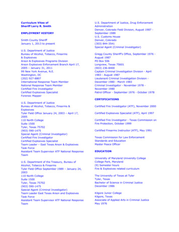
!Tail37-4FixedFree012162024(a) M 1.70.Figure 4.- Effect of free-rolling tail on longitudinal aerodynamic characteristics of model with zero control deflection at Oc Oo.25I
200-200.2I0 Fixed1 0Free0-. 2Crn-.44-.63-.8'D10201612a,deg8i .4. .0-4-20246a( a ) Concluded.F i g u r e 4.-26Continued.10121416
.8. 4 CA0a . deg(b) M 2.16.F i g u r e 4.-Continued.27
20(mtail, rpm(-201 -.2Tail0Fixed0 Free60zlb '1-.25'rlCm'I,a-. 44-.6D'#-.8224120016120,deg840-4-202468(b) Concluded.Figure 4.- Continued.2810121416
200@tail.rpmo-200Cn.20-.2Cm-. 4-. 6-.812Tail1000FixedFree864cN42DcU-2M 2.36.F i g u r e 4.-Continued.29I
200@tail, rpm-O200Tail.2Q Fixed0 Free505-. 2Cm4I-.E3 cD-.121202102104( c ) ConcludedF i g u r e 4.-30IContinued.1416
200*tailIrpm0-200CLi.,,.I. I '!,'II1::, :./ ;/.:!I;.20-tCm - . 2-.4-. 6fTailFixed1IIi'NiI0F i g u r e 4.-Continued.31
Tail0 FixedFree543CO213OB! !-4 -20246a(d) Concluded.Figure 4.- Concluded.32101116
200-2oc.20-. Cm-.-.181‘A011FreeICN/D-4162024Figure 5.- Effect of free-rolling tail on longitudinal aerodynamic characteristics of model with zero control deflection at @c 45O.33
200I@ t a i l , rPmo-200. .9-1.20 Fixed00 Free-.2Crn-.44B-.63P*-.8102c16P12a,deg40-4d68(a) Concluded.Figure 5.- Continued.34101214D'
aI2003- QE D-20I.,. 1Ik B.#cmi,- . 1-. f.aM 3-. e.4-1.00c*Tailli00FixedFree' d1c)J86/cN42d0-201Figure 5.-2428Continued.35
Tail00ixedree6543 'D21024106(b) Concluded.Figure 5.36Continued.121416
200@ t a i l , rpm-0200.2C-. iCm-.L8-.'A-.I0-1.1100FixedFree1cN20F i g u r e 5.-242832Continued.37
20-201.iCin-.25,-. 4.4-.63-.CO-.8?.24f20I16.4.0-4-2--d02468(c) Concluded.Figure 5.38Continued.LO121416
��8(a)F i g u r e 5.-12a. deg2M 2-86,Continued,39I
@tail. .Tail0Fixed-0 Free432 'D1024ta(d) Concluded.F i g u r e 5.40Concluded.10121416
200‘tailIrpm!i!I-200.2i0!-. 2-. 4.i-. 6Cm-. 8-1.0-1.2.8-1.4 . 4 CA0I(Canard0t0OnOff/tAcN‘ !j- .L-408(a)12162024M 1.70.F i g u r e 6.- E f f e c t of c a n a r d s on l o n g i t u d i n a l aerodynamic c h a r a c t e r i s t i c s o f model w i t h f r e e - r o l l i n g t a i l a t @c Oo.41I
iI200@tailsrpm-0200.2II0Canard-. 200OnOff- 4cm - . 6-. 8-1.04-1.23- 1.4I20!01612II8-a.d egII1i4I10IIi-4-E2468Ct(a) Concluded.Figure 6.- Continued.426
200Otail.0rpm-2oc.20-. 2Cm-. 4-. 6-. F i g u r e 6.2024M 2.16.-Continued.43
200I'I%ail .rpm-:IE-l -E0200II.2I0-.2:anardI'OnOff1010-. 4IIII-. 6Cm 5Ii- 85I I 2 cD1121416
200oQtailsrpm- 200.20II!-. 2fII-.4II1-.6bCmi-. 8-1.0-1.2-1.4.I-Cli1cI 81Canar4I:OnOffI4i II!iIr -.a-404(C)812162024M 2.36-F i g u r e 6.- Continued.45
.i!l ECanard I0On,Off0IIII1i5II!I4iI3IIIcDjI1 4III3IiI1iI 608IOConcluded.F i g u r e 6.46Continued.121416
Canard100OnOff(d) M 2.86.Figure 6.- Continued.47
I.14II-1 -jI!I- 11 -!!Ii1IIi4,IIIICanard0h,OnOffIc!!.\143Y1J 1III 5cDI0I1:IIiiii IiIIIIi.jIIIjIII1468CL(d) Concluded.F i g u r e 6.-48Concluded.6
[. .iI 1-Tail0. .0!FixedFreeiIIijIijIIiI-c.2IIII.-0ii. 2iI I.I .T-rr, i!Ia. d e gM 1.70.Figure 7.- E f f e c t of f r e e - r o l l i n g t a i l on l a t e r a l aerodynamic character Oo.istics of model w i t h zero c o n t r o l d e f l e c t i o n . a taC49
1216a. d e g(b) M 2-16.F i g u r e 7.-50Continued.202428
20('I1--trLI-- --t-1C"0-1CY'. ia12a , deg162024(e) M 2.36.Figure 7.-Continued.51
I.iI!j t---4IIc-II.2I0- .2-tIiII .-Ii.i.!3 4 --c.*.-iM. .IIIa(d)M 2.86.Figure 7.-Concluded.52-.-.I
E/;20@ t a i l . rpm-20Tail!-FixediFreeIIiI iIC"i(I'IIi-1I .I1iIiIII. .i'6.201.i-. 2iI!i2.I'.I0-2.!3.I0.1.042a. d e g(a) M 1 . 7 0 .Figure 8.- E f f e c t of f r e e - r o l l i n g t a i l on l a t e r a l aerodynamic characteri s t i c s of model w i t h zero c o n t r o l d e f l e c t i o n a t Oc 26.6O.53
200@ t a i l , rpm-0200,I0C"-1-22-?8(b) M 2.16.Figure 8 , - Continued.5432
20(*tail.rpm[-20(I. rII.--*II-. -I.IOC12IIIII--0-44aI12a, deg1620242832(c) M 2.36.Figure 8.- Continued.55
200* t a i l , rpma-20ctITai0Fixei0 Free10c"-1j--2I-- t--I1IL Ij .2-d0I.2!.:.*:j 'III2"It0-2.A-4.I!0-.'.240M 2.86.Figure 8. - Concluded.56- -.- . . .,,,28'--i- I32
20*tailII&rpm-3I 1-20Tail0Fixed0 FreeiiIc"I-1KLncnI1!1-1I1!II1I I. .I. I1icEc!--.2I1I0I!i!-. 2iIIv-iIII.III'IiIQP-IIIII!I- t-4048(a)12a. d e g1620242832M 1.70,Figure 9.-E f f e c t of f r e e - r o l l i n g t a i l on l a t e r a l aerodynamic characteristics of model w i t h zero c o n t r o l d e f l e c t i o n a t @c 45O.57
.200,@tail, rpmo-2001c"0-1.20-. 220Ii-2-4081216(b) M 2.16,Figure 9.- Continued.58202428
20*tail, rpm-20Tail00c"FixedFreeBi-GF .2Ic 2-rctI--0-. 2I'D Q?- 1!i84i12320242832a, d e g(c)M 2.36.Figure 9.- Continued.59
.I . 1.4- .ii. -1IIiIIIIiLritI. I!Ii. L-1I!1 1 IIII.III I- .,I- 1 .(a)M 2.86,F i g u r e 9.- C o n c l u d e d .60L
I IdI4 7EIII II II 1I40On0OffI II IIII ITIII1IIIk1I IIL' LI rrkIII II II III-2-8-4Y'IIIL IP1 TI IIII II III II0-. 2.I,I0.24I(a)E11216L"!428M 1.70.Figure 10.- E f f e c t of canards on l a t e r a l aerodynamic characteristics of model w i t h a f r e e - r o l l i n g t a i l a t ' c Oo.61
.20 cz.2-404(b)16degM 2.16.F i g u r e 10.-621280.Continued.202428
f200@tail, rpm0-200mULdi4rlCanard1Cn0-1.2O Cz. 22CY0-24a121620242a(c) M 2.36,F i g u r e 10.-Continued.63
-a-40a412a, deg(a) M 2.86.F i g u r e 10.64Concluded,16202428
4020@tail, rpm-20-40C"1.20 Cl-. 2000ATailFixedFreeFixedFreedroll .de!00-0.5-0.5CY24(a)F i g u r e 11.-2832M 1.70.R o l l - c o n t r o l c h a r a c t e r i s t i c s of model w i t h f i x e d and f r e e - r o l l i n gt a i l a t c Oo.Two c a n a r d s d e f l e c t e d .65
400200otailIorPm-200-400CY(b) M 2.16.F i g u r e 11.-66Continued.
40i20@tailIiII--Arpm-- rp-20-40C"II-1020CYTailFixedFreed;