Transcription
03 1587132079 ch02.qxd3/27/082:33 PMPage 45CHAPTER 2Basic Switch Concepts and ConfigurationObjectivesUpon completion of this chapter, you will be able to answer the following questions: What are the principal Ethernet operations pertinent to a 100/1000/10000 Mbps LAN in theIEEE 802.3 standard? How do you configure a switch for operation ina network designed to support voice, video, anddata communication? What are the functions that enable a switch toforward Ethernet frames in a LAN? How do you configure basic security on a switchthat operates within a network designed to support voice, video, and data communication?Key TermsThis chapter uses the following key terms. You can find the definitions in the Glossary.read-only memory (ROM)page 49organizational unique identifier (OUI)half duplex page 49page 65page 71Trivial File Transfer Protocol (TFTP)floods page 51page 54propagation delay page 54store-and-forwardGUInon-volatile RAM (NVRAM)page 51virtual LAN (VLAN)page 49page 59Simple Network Management Protocol(SNMP) page 65full duplex page 49auto-MDIXcut-through switchingpage 59encryptionspoofpage 80page 90page 100Cisco Discovery Protocol (CDP)page 101
03 1587132079 ch02.qxd463/27/082:33 PMPage 46LAN Switching and Wireless, CCNA Exploration Companion GuideIn this chapter, you build upon the skills learned in CCNA Exploration 4.0: NetworkFundamentals, reviewing and reinforcing these skills. You also learn about some key malicious threats to switches and learn to enable a switch with a secure initial configuration.Introduction to Ethernet/802.3 LANsIn this section, you learn about key components of the Ethernet standard that play a significant role in the design and implementation of switched networks. You explore how Ethernetcommunications function and how switches play a role in the communication process.Key Elements of Ethernet/802.3 NetworksEthernet/802.3 networks rely on carrier sense multiple access/collision detect (CSMA/CD),unicast transmission, broadcast transmission, multicast transmission, duplex settings, switchport settings, and MAC address table management. We next review each of these conceptsfrom CCNA Exploration 4.0: Networking Fundamentals.CSMA/CDEthernet signals are transmitted to every host connected to the LAN using a special set ofrules to determine which station can access the network. The set of rules that Ethernet usesis based on the IEEE carrier sense multiple access/collision detect (CSMA/CD) technology.Recall that CSMA/CD is used only with half-duplex communication typically found withhubs. Full-duplex ports do not use CSMA/CD.In the CSMA/CD access method, all network devices that have messages to send must listen before transmitting. If a device detects a signal from another device, it waits for a specified amount of time before attempting to transmit. When there is no traffic detected, adevice transmits its message. While this transmission is occurring, the device continues tolisten for traffic or collisions on the LAN. After the message is sent, the device returns to itsdefault listening mode.If the distance between devices is such that the latency of the signals of one device meansthat signals are not detected by a second device, the second device may also start to transmit. The media now has two devices transmitting signals at the same time. The messagespropagate across the media until they encounter each other. At that point, the signals mixand the messages are destroyed, a collision. Although the messages are corrupted, the jumble of remaining signals continues to propagate across the media.When a device is in listening mode, it can detect when a collision occurs on the sharedmedia because all devices can detect an increase in the amplitude of the signal above thenormal level. When a collision occurs, the other devices in listening mode, as well as all thetransmitting devices, detect the increase in the signal amplitude. Every device that is transmitting continues to transmit to ensure that all devices on the network detect the collision.
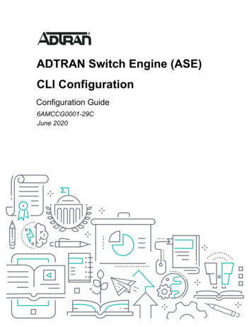
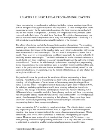
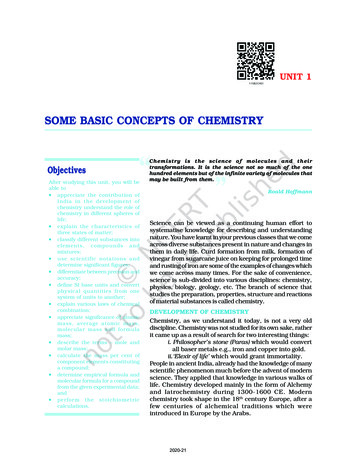
03 1587132079 ch02.qxd3/27/082:33 PMPage 47Chapter 2: Basic Switch Concepts and Configuration47When a collision is detected, the transmitting devices send out a jamming signal. The jamming signal notifies the other devices of a collision so that they invoke a backoff algorithm.This backoff algorithm causes all devices to stop transmitting for a random amount of time,which allows the collision signals to subside.After the delay has expired on a device, the device goes back into the “listening beforetransmit” mode. A random backoff period ensures that the devices that were involved in thecollision do not try to send traffic again at the same time, which would cause the wholeprocess to repeat. However, during the backoff period, a third device may transmit beforeeither of the two involved in the collision have a chance to retransmit.Ethernet CommunicationsReference Figure 2-1 for the Ethernet communications discussion that follows. Communicationsin a switched LAN occur in three ways: unicast, broadcast, and multicast.Figure 2-1Ethernet CommunicationsUnicastBroadcastMulticastClient GroupWith unicast communication, a frame is sent from one host and addressed to one specificdestination. In unicast transmission, there is just one sender and one receiver. Unicast transmission is the predominant form of transmission on LANs and within the Internet.Examples of unicast transmissions include HTTP, SMTP, FTP, and Telnet.With broadcast communication, a frame is sent from one address to all other addresses. Inthis case, there is just one sender, but the information is sent to all connected receivers.Broadcast transmission is essential when sending the same message to all devices on theLAN. An example of a broadcast transmission is the address resolution query that theaddress resolution protocol (ARP) sends to all computers on a LAN.
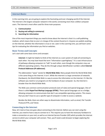
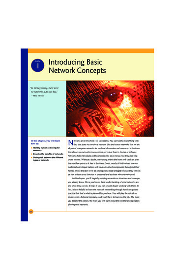
03 1587132079 ch02.qxd483/27/082:33 PMPage 48LAN Switching and Wireless, CCNA Exploration Companion GuideWith multicast communication, a frame is sent to a specific group of devices or clients.Multicast transmission clients must be members of a logical multicast group to receive theinformation. An example of multicast transmission is the video and voice transmissionsassociated with a network-based, collaborative business meeting.To briefly review the Ethernet frame structure, recall that the Ethernet frame adds headersand trailers around the Layer 3 PDU to encapsulate the message being sent. Both theEthernet header and trailer have several sections (or fields) of information that are used bythe Ethernet protocol. Figure 2-2 shows the structure of the current Ethernet frame standard,the revised IEEE 802.3 (Ethernet).Figure 2-2Ethernet FrameIEEE 802.37166246 to 15004PreambleStart gth/Type802.2 Header andDataFrame CheckSequenceThe Preamble (7 bytes) and Start Frame Delimiter (SFD) (1 byte) fields are used for synchronization between the sending and receiving devices. These first 8 bytes of the frame areused to get the attention of the receiving nodes. Essentially, the first few bytes tell thereceivers to get ready to receive a new frame.The Destination MAC Address field (6 bytes) is the identifier for the intended recipient.This address is used by Layer 2 to assist a device in determining whether a frame isaddressed to it. The address in the frame is compared to the MAC address in the device. Ifthere is a match, the device accepts the frame.The Source MAC Address field (6 bytes) identifies the frame’s originating NIC or interface.Switches use this address to add to their lookup tables.The Length/Type field (2 bytes) defines the exact length of the frame’s data field. This fieldis used later as part of the Frame Check Sequence (FCS) to ensure that the message wasreceived properly. Only a frame length or a frame type can be entered here. If the purposeof the field is to designate a type, the Type field describes which protocol is implemented.When a node receives a frame and the Length/Type field designates a type, the node determines which higher layer protocol is present. If the two-octet value is equal to or greaterthan 0x0600 hexadecimal or 1536 decimal, the contents of the Data Field are decodedaccording to the protocol indicated; if the two-byte value is less than 0x0600, the value represents the length of the data in the frame.The Data and Pad fields (46 to 1500 bytes) contain the encapsulated data from a higherlayer, which is a generic Layer 3 PDU, or more commonly, an IPv4 packet. All frames mustbe at least 64 bytes long (minimum length aides the detection of collisions). If a small packetis encapsulated, the Pad field is used to increase the size of the frame to the minimum size.
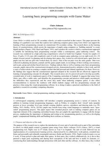
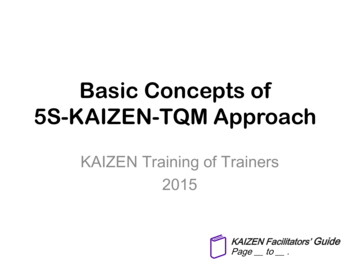
2:33 PMPage 49Chapter 2: Basic Switch Concepts and Configuration49The FCS field (4 bytes) detects errors in a frame. It uses a cyclic redundancy check (CRC).The sending device includes the results of a CRC in the FCS field of the frame. The receiving device receives the frame and generates a CRC to look for errors. If the calculationsmatch, no error has occurred. If the calculations do not match, the frame is dropped.An Ethernet MAC address is a two-part 48-bit binary value expressed as 12 hexadecimaldigits. The address formats might be similar to 00-05-9A-3C-78-00, 00:05:9A:3C:78:00, or0005.9A3C.7800. All devices connected to an Ethernet LAN have MAC-addressed interfaces. The NIC uses the MAC address to determine whether a message should be passed tothe upper layers for processing. The MAC address is permanently encoded into a read-onlymemory (ROM) chip on a NIC. This type of MAC address is referred to as a burned-inaddress (BIA). Some vendors allow local modification of the MAC address. The MACaddress is made up of the organizational unique identifier (OUI) and the vendor assignment number. The OUI is the first part of a MAC address. It is 24 bits long and identifiesthe manufacturer of the NIC card. The IEEE regulates the assignment of OUI numbers.Within the OUI are 2 bits that have meaning only when used in the destination address, thebroadcast or multicast bit and the locally administered address bit, shown in Figure 2-3.Figure 2-3OUI CompositionLocal3/27/08Broadcast03 1587132079 ch02.qxdOUIVendorAssignedThe broadcast or multicast bit in a MAC address indicates to the receiving interface that theframe is destined for all or a group of end stations on the LAN segment.The locally administered address bit indicates whether the vendor-assigned MAC addresscan be modified locally.The vendor-assigned part of the MAC address is 24 bits long and uniquely identifies theEthernet hardware. It can be a BIA or it can be modified by software indicated by the local bit.Duplex SettingsThere are two types of duplex settings used for communications on an Ethernet network:half duplex and full duplex.Half-duplex communication relies on unidirectional data flow where sending and receivingdata are not performed at the same time. This is similar to how walkie-talkies or two-wayradios function in that only one person can talk at any one time. If someone talks whilesomeone else is already speaking, a collision occurs. As a result, half-duplex communication implements CSMA/CD to help reduce the potential for collisions and detect them whenthey do happen. Half-duplex communications have performance issues due to the constantwaiting, because data can flow in only one direction at a time. Half-duplex connections aretypically found in older hardware, such as hubs. Nodes that are attached to hubs that share
03 1587132079 ch02.qxd503/27/082:33 PMPage 50LAN Switching and Wireless, CCNA Exploration Companion Guidetheir connection to a switch port must operate in half-duplex mode because the end computers must be able to detect collisions. Nodes can operate in a half-duplex mode if the NICcard cannot be configured for full-duplex operations. In this case, the port on the switchdefaults to a half-duplex mode as well. Because of these limitations, full-duplex communication has replaced half-duplex in more current hardware.In full-duplex communication, data flow is bidirectional, so data can be sent and received atthe same time. The bidirectional support enhances performance by reducing the wait timebetween transmissions. Most Ethernet, Fast Ethernet, and Gigabit Ethernet NICs sold todayoffer full-duplex capability. In full-duplex mode, the collision-detect circuit is disabled.Frames sent by the two connected end nodes cannot collide because the end nodes use twoseparate circuits in the network cable. Each full-duplex connection uses only one port. Fullduplex connections require a switch that supports full duplex or a direct connection betweentwo nodes that each support full duplex. Nodes that are directly attached to a dedicatedswitch port with NICs that support full duplex should be connected to switch ports that areconfigured to operate in full-duplex mode.Standard, shared hub-based Ethernet configuration efficiency is typically rated at 50 to 60 percent of the 10 Mbps bandwidth. Full-duplex Fast Ethernet, compared to 10 Mbps bandwidth,offers 100 percent efficiency in both directions (100 Mbps transmit and 100 Mbps receive).Switch Port SettingsA port on a switch needs to be configured with duplex settings that match the media type.Later in this chapter, you will configure duplex settings. The Cisco Catalyst switches havethree settings: The auto option sets autonegotiation of duplex mode. With autonegotiation enabled,the two ports communicate to decide the best mode of operation. The full option sets full-duplex mode. The half option sets half-duplex mode.For Fast Ethernet and 10/100/1000 ports, the default is auto. For 100BASE-FX ports, thedefault is full. The 10/100/1000 ports operate in either half- or full-duplex mode when theyare set to 10 or 100 Mbps, but when set to 1,000 Mbps, they operate only in full-duplex mode.NoteAutonego
Figure 2-1 Ethernet Communications Chapter 2: Basic Switch Concepts and Configuration 47 Unicast Broadcast Multicast Client Group With unicast communication, a frame is sent from one host and addressed to one specific destination. In unicast transmission, there is just one sender and one receiver. Unicast trans- mission is the predominant form of transmission on LANs and within the Internet .