Transcription
Installation and Operation ManualThermo Scientific Jewett Laboratory Freezers
2010 Thermo Fisher Scientific. All rights reserved.“Suva ” is a registered trademark of DuPont.All other trademarks are the property of Thermo Fisher Scientific Inc. andits subsidiaries.
Thermo Scientific Jewett Laboratory FreezersInstallation and OperationTable of Contents1Introduction. . . . . . . . . . . . . . . . . . . . . . . . . . . . . . . . . . . . . . . . . . . . . . . . . . . . . . . . . . . . . . . . . . . . . . . 12Safety Precautions . . . . . . . . . . . . . . . . . . . . . . . . . . . . . . . . . . . . . . . . . . . . . . . . . . . . . . . . . . . . . . . . . 13Pre-Installation . . . . . . . . . . . . . . . . . . . . . . . . . . . . . . . . . . . . . . . . . . . . . . . . . . . . . . . . . . . . . . . . . . . . 13.145678Unpacking. . . . . . . . . . . . . . . . . . . . . . . . . . . . . . . . . . . . . . . . . . . . . . . . . . . . . . . . . . . . . . . . . . . . . . . . . . . . . .1Installation. . . . . . . . . . . . . . . . . . . . . . . . . . . . . . . . . . . . . . . . . . . . . . . . . . . . . . . . . . . . . . . . . . . . . . . . 24.1Location . . . . . . . . . . . . . . . . . . . . . . . . . . . . . . . . . . . . . . . . . . . . . . . . . . . . . . . . . . . . . . . . . . . . . . . . . . . . . . .24.2Wiring . . . . . . . . . . . . . . . . . . . . . . . . . . . . . . . . . . . . . . . . . . . . . . . . . . . . . . . . . . . . . . . . . . . . . . . . . . . . . . . . .24.3Leveling . . . . . . . . . . . . . . . . . . . . . . . . . . . . . . . . . . . . . . . . . . . . . . . . . . . . . . . . . . . . . . . . . . . . . . . . . . . . . . .24.4Shelves and Drawers . . . . . . . . . . . . . . . . . . . . . . . . . . . . . . . . . . . . . . . . . . . . . . . . . . . . . . . . . . . . . . . . . . . . .24.5Door Seal . . . . . . . . . . . . . . . . . . . . . . . . . . . . . . . . . . . . . . . . . . . . . . . . . . . . . . . . . . . . . . . . . . . . . . . . . . . . . .24.6Solid Doors . . . . . . . . . . . . . . . . . . . . . . . . . . . . . . . . . . . . . . . . . . . . . . . . . . . . . . . . . . . . . . . . . . . . . . . . . . . . .24.7Final Checks . . . . . . . . . . . . . . . . . . . . . . . . . . . . . . . . . . . . . . . . . . . . . . . . . . . . . . . . . . . . . . . . . . . . . . . . . . . .24.8Control Panel Features . . . . . . . . . . . . . . . . . . . . . . . . . . . . . . . . . . . . . . . . . . . . . . . . . . . . . . . . . . . . . . . . . . . .3Control Panel . . . . . . . . . . . . . . . . . . . . . . . . . . . . . . . . . . . . . . . . . . . . . . . . . . . . . . . . . . . . . . . . . . . . . 35.1Display Functions . . . . . . . . . . . . . . . . . . . . . . . . . . . . . . . . . . . . . . . . . . . . . . . . . . . . . . . . . . . . . . . . . . . . . . . .45.2Setpoint Programming . . . . . . . . . . . . . . . . . . . . . . . . . . . . . . . . . . . . . . . . . . . . . . . . . . . . . . . . . . . . . . . . . . . .45.3Service Mode Parameters . . . . . . . . . . . . . . . . . . . . . . . . . . . . . . . . . . . . . . . . . . . . . . . . . . . . . . . . . . . . . . . . .4Operation. . . . . . . . . . . . . . . . . . . . . . . . . . . . . . . . . . . . . . . . . . . . . . . . . . . . . . . . . . . . . . . . . . . . . . . . . 56.1Temperature Settings . . . . . . . . . . . . . . . . . . . . . . . . . . . . . . . . . . . . . . . . . . . . . . . . . . . . . . . . . . . . . . . . . . . . .56.2Start Up . . . . . . . . . . . . . . . . . . . . . . . . . . . . . . . . . . . . . . . . . . . . . . . . . . . . . . . . . . . . . . . . . . . . . . . . . . . . . . .5Defrost . . . . . . . . . . . . . . . . . . . . . . . . . . . . . . . . . . . . . . . . . . . . . . . . . . . . . . . . . . . . . . . . . . . . . . . . . . . 57.1Automatic Defrost (-30 C Models Only) . . . . . . . . . . . . . . . . . . . . . . . . . . . . . . . . . . . . . . . . . . . . . . . . . . . . .57.2Manual Defrost (-20º Models Only) . . . . . . . . . . . . . . . . . . . . . . . . . . . . . . . . . . . . . . . . . . . . . . . . . . . . . . . . . .5Alarm Systems . . . . . . . . . . . . . . . . . . . . . . . . . . . . . . . . . . . . . . . . . . . . . . . . . . . . . . . . . . . . . . . . . . . . 68.1Operating the Alarm . . . . . . . . . . . . . . . . . . . . . . . . . . . . . . . . . . . . . . . . . . . . . . . . . . . . . . . . . . . . . . . . . . . . . .68.2Remote Alarm Terminals . . . . . . . . . . . . . . . . . . . . . . . . . . . . . . . . . . . . . . . . . . . . . . . . . . . . . . . . . . . . . . . . . .68.3Installing the Remote Alarm . . . . . . . . . . . . . . . . . . . . . . . . . . . . . . . . . . . . . . . . . . . . . . . . . . . . . . . . . . . . . . . .68.4Alarm Test . . . . . . . . . . . . . . . . . . . . . . . . . . . . . . . . . . . . . . . . . . . . . . . . . . . . . . . . . . . . . . . . . . . . . . . . . . . . .68.4.1 Theory of Operation . . . . . . . . . . . . . . . . . . . . . . . . . . . . . . . . . . . . . . . . . . . . . . . . . . . . . . . . . . . . . . . .68.4.2 Alarm Test Procedure . . . . . . . . . . . . . . . . . . . . . . . . . . . . . . . . . . . . . . . . . . . . . . . . . . . . . . . . . . . . . . .6i
910Chart Recorders . . . . . . . . . . . . . . . . . . . . . . . . . . . . . . . . . . . . . . . . . . . . . . . . . . . . . . . . . . . . . . . . . . . 79.1Set Up and Operation. . . . . . . . . . . . . . . . . . . . . . . . . . . . . . . . . . . . . . . . . . . . . . . . . . . . . . . . . . . . . . . . . . . . .79.2Power Supply . . . . . . . . . . . . . . . . . . . . . . . . . . . . . . . . . . . . . . . . . . . . . . . . . . . . . . . . . . . . . . . . . . . . . . . . . . .79.3Changing Chart Paper . . . . . . . . . . . . . . . . . . . . . . . . . . . . . . . . . . . . . . . . . . . . . . . . . . . . . . . . . . . . . . . . . . . .79.4Calibration Adjustment . . . . . . . . . . . . . . . . . . . . . . . . . . . . . . . . . . . . . . . . . . . . . . . . . . . . . . . . . . . . . . . . . . . .7Drawers (Optional) . . . . . . . . . . . . . . . . . . . . . . . . . . . . . . . . . . . . . . . . . . . . . . . . . . . . . . . . . . . . . . . . . 810.1 Removing the Drawers . . . . . . . . . . . . . . . . . . . . . . . . . . . . . . . . . . . . . . . . . . . . . . . . . . . . . . . . . . . . . . . . . . . .810.2 Reinstalling the Drawers. . . . . . . . . . . . . . . . . . . . . . . . . . . . . . . . . . . . . . . . . . . . . . . . . . . . . . . . . . . . . . . . . . .810.3 Changing Drawer Slide Position . . . . . . . . . . . . . . . . . . . . . . . . . . . . . . . . . . . . . . . . . . . . . . . . . . . . . . . . . . . . .81112Cleaning . . . . . . . . . . . . . . . . . . . . . . . . . . . . . . . . . . . . . . . . . . . . . . . . . . . . . . . . . . . . . . . . . . . . . . . . . 811.1Cleaning the Drawers or Shelves . . . . . . . . . . . . . . . . . . . . . . . . . . . . . . . . . . . . . . . . . . . . . . . . . . . . . . . . . . . .811.2Cleaning the Condenser. . . . . . . . . . . . . . . . . . . . . . . . . . . . . . . . . . . . . . . . . . . . . . . . . . . . . . . . . . . . . . . . . . .8Troubleshooting . . . . . . . . . . . . . . . . . . . . . . . . . . . . . . . . . . . . . . . . . . . . . . . . . . . . . . . . . . . . . . . . . . . 9ii
Thermo Scientific Jewett Laboratory Freezers1IntroductionThis manual provides installation and operation instructions forlaboratory freezers with preset temperature setpoints of -20ºCand -30ºC.Installation and Operation2In this manual and on labels attached to this product, the wordsWARNING and CAUTION mean the following: WARNING: apotentially hazardous situation which, if notavoided, could result in serious injury or death.The control system, standard on all models, includes: Key-operated power and alarm switchPreset temperature setpointDigital temperature display with 0.1ºC resolutionGraphic temperature displayAudible and visual power failure indicatorsAlarm silence, ringback, and automatic reset functionsPushbutton alarm testOther standard features include: Safety Precautions CAUTION:a potentially hazardous situation which, if notavoided, may result in minor or moderate injury ordamage to the equipment.Before installing, using or maintaining this product, please besure to read this manual and product warning labels carefully.Failure to follow these instructions may cause this product tomalfunction, which could result in injury or damage.Below are important safety precautions that apply to this product:Remote alarm contactsCFC-free refrigerantCFC-free foamed in-place urethane insulationQuiet, hermetically sealed refrigeration compressorsKeyed door locks Use this product only in the way described in the productliterature and in this manual. Before using it, verify that thisproduct is suitable for its intended use. Do not modify system components, especially the controller.Use OEM exact replacement equipment or parts. Before use,confirm that the product has not been altered in any way. Your unit must be properly grounded in conformity withnational and local electrical codes. Never connect the unit tooverloaded power sources. Disconnect the unit from all power sources before cleaning,troubleshooting, or performing other maintenance on theproduct or its controls.33.1Pre-InstallationUnpackingAt delivery, examine the exterior for physical damage while thecarrier’s representative is present. If exterior damage is present,carefully unpack and inspect the unit and all accessories fordamage.If there is no exterior damage, unpack and inspect the equipmentwithin five days of delivery. If you find any damage, keep thepacking materials and immediately report the damage to thecarrier. Do not return goods without written authorization.When submitting a claim for shipping damage, request that thecarrier inspect the shipping container and equipment.1
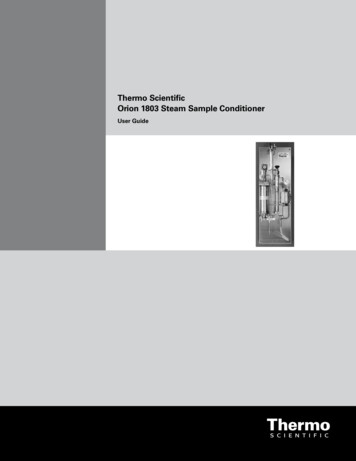
Thermo Scientific Jewett Laboratory Freezers4Installation and OperationInstallationCAUTION! Improper operation of the equipmentcould result in dangerous conditions. Follow allinstructions and operate within design limits noted onthe dataplate.4.1LocationInstall the unit in a level area free from vibration with a minimumof 6 inches of space on the sides and rear and 12 inches at the top.Do not position the equipment in direct sunlight or near heatingdiffusers, radiators, or other sources of heat. The ambienttemperature range at the location must be 59 to 90 F(15 to 32 C).4.2WiringBefore connecting your freezer to a power source, be sure tocheck the dataplate for correct voltage. Standard NEMA plugsare provided with all units. Wiring diagrams are attached to theback of the cabinet.CAUTION! Connect the equipment to the correctpower source. Incorrect voltage can result in severedamage to the equipment.WARNING! For personal safety and trouble-freeoperation, this unit must be properly grounded beforeit is used. Failure to ground the equipment may causepersonal injury or damage to the equipment. Alwaysconform to the National Electrical Code and localcodes. Do not connect unit to already overloadedpower lines.Figure 1. Shelf Support Hanger4.5Door SealDoor seal integrity is critical for freezers. A loose fitting gasketallows moist air to be drawn into the cabinet, resulting in quickerfrost buildup on the evaporator coil, longer running time, poortemperature maintenance, and increased operation cost.To check the door seal, complete the following steps:1. Open the door.2. Insert a strip of paper (a couple of inches wide) between thedoor gasket and the cabinet flange and close the door.3. Slowly pull the paper strip from the outside. You should feelsome resistance.4. Repeat this test at 4-inch intervals around the door. If thedoor does not seal properly, replace the gasket.4.6Solid DoorsAlways connect the equipment to a dedicated (separate) circuit.Electrical codes require fuse or circuit breaker protection forbranch circuit conductors. Use time delay fuses for #12 AWGcircuits.Solid doors stay open if opened 90 degrees. Solid door springtension cannot be adjusted.4.3Before start up, complete the following steps:LevelingThe unit must be level. Use thin sheets of metal to level unitsequipped with casters.4.4Shelves and Drawers4.7Final Checks1. Make sure that the unit is free of all wood or cardboardshipping materials, both inside and outside.2. Verify that the unit is connected to a dedicated circuit.Plasma freezers come standard with drawers. All other freezerscome standard with wire shelves. -20 C enzyme freezers comestandard with wire shelves which have a rail at the front.Additional drawers and/or shelves are offered as availableoptions.For safety in shipping, the shelves are packaged and securedinside the cabinet. Insert the shelf support hangers (included withthe shelves) into the built-in shelf supports (located on the insidewalls of the cabinet interior) at the desired locations. Position theshelves on the flat supports (refer to Figure 1).Note:The number of shelves supplied per cabinet variesaccording to type of unit and size of cabinet.2
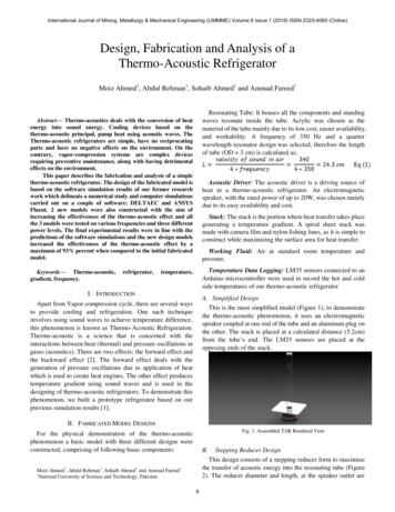
Thermo Scientific Jewett Laboratory Freezers5Installation and OperationControl Panel31452910Key Switch678Figure 2. Laboratory Freezer Control Panel5.1Control Panel FeaturesThe control panel is located on the top right side of the freezer.You can use the three pushbuttons (#5, #8, and #9 in Figure 2) tochange the temperature display (#1) or to adjust temperature andalarm setpoints. The thermometer display (#2) provides a quickvisual indicator of current cabinet temperature and alarmconditions.Before starting up your freezer, take some time to review thecontrol panel functions:1. Main temperature display — during normal operation, showscabinet temperature in degrees Celsius, as measured by thesensor inside the cabinet. You can use the buttons to displayother values such as setpoints and extreme values.The number in the main display flashes when you arechanging a value.2. Thermometer — shows cabinet temperature and alarmconditions. There are 10 horizontal bars: 9 are displayedduring normal operation, the tenth (top) bar indicates a warmalarm condition.The number of bars illuminated indicatesapproximate cabinet temperature. Depending on alarmsettings, 4 or 5 bars illuminated indicate that the cabinet is atsetpoint.For example, suppose that the cabinet temperature setpoint is-30ºC and that the warm and cold alarm setpoints are -26ºCand -34ºC. Then the number of bars illuminated indicatescabinet temperature as follows:bulb only1 bar2 bars3 bars4 bars5 bars-34 (cold alarm)-33.2-32.4-31.6-30.8-30 (setpoint)6 bars7 bars8 bars9 bars10 bars-29.2-28.4-27.6-26.8-26(warm alarm)When cabinet temperature exceeds the warm alarm setpoint,the top of the thermometer flashes. When temperature islower than the cold alarm setpoint, the bulb flashes.When you are in programming mode (described in Table 2)the thermometer shows the setpoint value you are changing.3. Power failure — illuminated when the main power supply isinterrupted. In this case the audible alarm also sounds.4. Service required — illuminated when the controller is inservice programming mode or when simulated warm or coldalarm conditions are failing to occur during an alarm test.5. Increase — pushbutton used to increase setpoint values inprogramming mode and for various display functions.6. Door ajar — illuminated when the freezer door is open andthe alarm is activated (key switch turned to the alarmposition). (This feature is not available for 45 ft3 sliding glassdoor models.)7. Battery low — illuminated when the backup battery is low.8. Decrease — pushbutton used to decrease setpoint values inprogramming mode and for various display functions.9. Scan — pushbutton used to change the main display and forvarious other functions.10. Audible alarm — illuminates during warm and cold alarmconditions.For full descriptions of display and programming functions, referto Tables 1 and 2 on page 4.3
Thermo Scientific Jewett Laboratory Freezers5.2Installation and OperationDisplay FunctionsTable 2.Control Panel Display Functions)FunctionMeaningSequenceDisplayNormal operationDefault display whilefreezeris running—Temperature display, thermometer show cabinet temperature.Cold excursionShow coldest cabinet temperaturesince last startup or resetPressThermometer, display show cold excursion while button ispressed.Warm excursionShow warmest cabinet temperaturesince last startup or resetPressThermometer, display show warm excursion while button ispressed.MuteSilence audible alarmPress ScanThermometer, display show cabinet temperature, alarm iconcontinues to flash.ResetReturn to default display afterexcursion or alarm conditionPressandsimultaneously, holdfor five secondsExcursion values are reset; thermometer, display show cabinettemperature. Display blinks twice to confirm reset.Alarm testTest by simulating warm alarmconditionsPressand Scansimultaneously, holdfor five secondsDisplay shows simulated cabinet temperature, alarms flash andsound as appropriate. Display blinks twice when test is started.Alarms are cleared when test is completed.5.3Setpoint ProgrammingTo enter programming mode, make sure that the key switch is in position 1 (see Figure 3), pressfirst value displayed is the cabinet temperature setpoint.Table 3.Setpoint Programming FunctionsFunctionProgramming SequenceAdjust cabinet temperature setpointEnter programming mode by pressing Scan and holding for about 5 seconds. The display will go blank, thendisplay “Prg”. On release of the button, the current cabinet temperature setpoint value flashes in theandto adjust the setpoint. The displaytemperature display and is shown on the thermometer. Useautomatically returns to normal operating mode 30 seconds after the last key entry or after scrolling throughall available functions and parameters.Adjust cold alarm setpointEnter programming mode and press Scan repeatedly. When the current cold alarm setpoint value flashes inandto adjust it.the temperature display, and the bottom LED of the thermometer is illuminated, useThe display automatically returns to normal operating mode 30 seconds after the last key entry or afterscrolling through all available functions and parameters.Adjust warm alarm setpointEnter programming mode and press Scan repeatedly. When the current warm alarm setpoint value flashes inandto adjust it. Thethe temperature display, and the top LED of teh thermometer is illuminated,usedisplay automatically returns to normal operating mode 30 seconds after the last key entry or after scrollingthrough all available functions and parameters.Note:5.4, hold for 5 seconds, and release. TheIn order to maintain setpoint security, the alarm setpoints cannot be adjusted when the key switch is in the alarm position.Service Mode ParametersThe service parameters are displayed after the alarm setpoints described in Section 5.3 above. To enter Service Mode, press and holdfor about 5 seconds (this can be done from any program mode when the alarms are not enabled). The display will go blank, then display“SEr” with the service wrench icon illuminated. On release of the button, the firmware checksum (read-only) will be displayed for about4 seconds. Pressing Scan repeatedly scrolls through the available functions. For any modifiable parameter you can use and toadjust the value. The display automatically returns to normal operating mode 30 seconds after the last key entry or after scrollingthrough all available functions and parameters.Table 4.Service Mode ParametersParameterDisplayNotes1. OffsetValue in main display, single barilluminated in thermometerCenter air temperature calibration. Default value is 0 (maximum or - 10.0).2. Network addressnEt (2 sec.); Adr (2 sec.); then valueCan only be modified by RS-485 communications software.3. Defrost probetemperaturedEF (2 sec.); Prb (2 sec.); then valueDisplay only.4
Thermo Scientific Jewett Laboratory Freezers6Operation6.1Temperature SettingsThe factory default temperature settings are: -30 C for automatic defrost freezers, including plasmafreezers.-20 C for manual defrost freezers, including enzymefreezers.To change the factory temperature settings, refer to theinstructions in Section 5.3.6.2Start UpTo start up the freezer, complete the following steps:1. Plug in the power cord.2. Insert the key in the switch and turn the power on, turning thekey switch to position 1. The compressor and the evaporatorfans should start immediately.3. Rotate the power switch to the ALARM ON position whenthe temperature drops below the warm alarm setpoint.All controls should now be fully operational, the alarm activated,and all visual indicators active.CAUTION! Do not operate strong radio emissionsources such as walkie-talkies within 3 feet of thefreezer. EMI and RFI can affect the performance of thecontrol systems.Installation and Operation77.1DefrostAutomatic Defrost (-30º C Models Only)The defrosting process on all -30 C freezers initiatesautomatically in response to a built-in timer.All models are set for one defrost cycle every six hours. Thedefrost cycle is 20 minutes. The cycle terminates automatically ifduring defrost the evaporator coil temperature exceeds 15ºC.7.2Manual Defrost (-20º Models Only)You should defrost the freezer whenever there is significant frostbuildup inside the cabinet.To defrost:1. Remove all products and place in another cold storagemedium.2. Turn off the unit and allow the interior to warm to roomtemperature.3. Dispose of the ice and wipe out any water standing in thebottom of the cabinet.CAUTION! When defrosting your freezer, never usesharp or heavy tools such as chisels or scrapers.Damage to the equipment can result. Let the ice meltenough so that it can be easily removed.If there is freezer odor, wash the interior with a solution ofbaking soda and warm water. Clean the exterior with anycommon household cleaning solution.5
Thermo Scientific Jewett Laboratory Freezers8Alarm Systems8.18.4The alarm system is designed to provide visual and audiowarning signals for both power failure and rise in temperature.The alarm is equipped with a battery backup.The alarm is activated when the freezer is operating and the keyswitch is turned to the third position (see Figure 2 on page 3).When the alarm system is activated, there is a Ringback feature:the audible alarm sounds approximately every six minutes untilthe alarm condition is corrected or the user resets.Refer to pages 3 and 4 for descriptions of alarm functions anddisplays.Remote Alarm TerminalsWhen you order an optional freestanding alarm package with thecabinet, remote alarm terminals are provided. These terminalsare located at the rear of the machine compartment. Theterminals are: Common, Normally Closed, and Normally Open.8.3Installing the Remote Alarm1. The remote alarm system has two keyhole slots on the backto hang the alarm system on the wall. Insert two screws, nolonger than a #12 truss-head type and spaced two inchesapart, into a wall and mount the alarm.2. Refer to Table 5 to make the following connections:a. Connect the common terminal on the cabinet switch tothe orange wire on the alarm.b. Connect the normally closed terminal on the cabinet tothe red wire on the alarm. This connection gives an alarmwhen the switch contacts open.Note:If you require the alarm signal when the switch contactsclose, connect the normally open terminal on the cabinetto the black wire on the alarm. The orange and red wiresmust be tied together in this application.Table 5.Alarm TestIt is important to test the alarm before loading your laboratoryfreezer with any critical product.Operating the Alarm8.2Installation and OperationWire GaugesWire GaugeTotal Wire Length(feet)Distance to Alarm1/2 Wire 123,3701,6858.4.1 Theory of OperationThe alarm test procedure applies to all models, whether theyhave factory-installed built-in alarms or field-installed remotealarms.While this procedure is very accurate and reliable, thetemperature of the refrigerated space does not change during thealarm test. The alarm test checks the temperature sensor which isartificially heated by a tiny, built-in thermoelectric heating unitwhich simulates warm conditions. The electronic control modulenotes the sensor temperature changes and the LED displays thesechanges.8.4.2 Alarm Test ProcedureWhen the unit is in operating temperature range, activate thealarm test by pressing and simultaneously and holding forabout five seconds. The test then automatically advances throughall steps and stops:1. The main display (Figure 2 on page 3, #1) and thethermometer (#2) show the warm alarm temperature.2. The alarm sounds and the alarm icon (#10) flashes.3. The test is now complete but the alarm continues to sounduntil the temperature on the display is back in the operatingrange.If the simulated alarm conditions do not occur during the first 10minutes of the alarm test, the service (wrench) icon illuminatesand the test is terminated. You can also terminate the testimmediately by turning the key switch to the second (non-alarm)position. When during the alarm test, the temperature displaydoes not change or the service icon illuminates, check the sensorconnections.After an alarm test has terminated, there is a 5-minute delaybefore the test can be run again.3. Plug the alarm system service cord into an electrical outlet.This alarm is designed for 115V/60 Hz, 115V/50 Hz, or100V/50 Hz operation.Note:The wiring diagram is attached to the inside of the alarmback cover.6
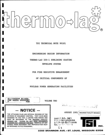
Thermo Scientific Jewett Laboratory Freezers9Installation and OperationChart Recorders9.2Panel-mounted six inch recorders are standard and factoryinstalled on all plasma freezers except for undercounter models,for which free-standing recorders are available as optionalaccessories. Recorders are available as optional accessories forall laboratory and enzyme freezers.9.1Set Up and OperationTo prepare the recorder to function properly, complete thefollowing steps:1. Open the recorder door to access the recorder.2. Connect the nine volt DC battery located at the recorder’supper right corner. This battery provides backup power.3. Install clean chart paper (refer to Section 9.3 below).4. Remove the plastic cap from the pen stylus and close therecorder door.Recorder operation begins when the system is powered on.Therecorder may not respond until the system reaches temperatureswithin the recorder’s range.9 Volt BatteryPower SupplyThe recorder normally uses AC power when the system isoperating. If AC power fails, the LED indicator flashes to alertyou to a power failure. The recorder continues sensing cabinettemperature and the chart continues turning for approximately24 hours with back-up power provided by the nine-volt battery.The LED indicator glows continuously when main power isfunctioning and the battery is charged.When the battery is low, the LED flashes to indicate that thebattery needs to be changed.9.3Changing Chart PaperTo change the chart paper, complete the following steps:1. Locate the pressure sensitive buttons at the front, upper leftof the recorder panel.2. Press and hold the Change Chart button (#3) for one second.The pen will move off the scale.3. Unscrew the center nut, remove the old chart paper, andinstall new chart paper. Carefully align the day and time withthe reference mark (a small groove on the left side of therecorder panel).4. Replace the center nut and hand tighten. Press the ChangeChart button again to resume temperature recording.Chart Buttons9.4Calibration AdjustmentThis recorder has been accurately calibrated at the factory andretains calibration even during power interruptions. If required,however, adjustments can be made as follows:ImprintingStylus1. Run the unit continuously at the control setpoint temperature.Continue steady operation for at least two hours to provideadequate time for recorder response.2. Measure cabinet center solution temperature with acalibrated temperature monitor. (Solution temperature ismeasured inside the sensor bottles — see .)3. Compare the recorder temperature to the solutiontemperature. If necessary, adjust recorder by pressing the left(#1) and right (#2) chart buttons.ReferenceMarkHub-Nut andRetaining WireChartNote:The stylus does not begin to move until the button is heldfor five seconds.Figure 2. Chart RecorderCHANGE CHART312Figure 3. Chart Buttons7
Thermo Scientific Jewett Laboratory Freezers10 Drawers (Optional)Installation and Operation10.3 Changing Drawer Slide PositionThe drawers in all models can be removed for cleaning oradjustment.10.1 Removing the DrawersTo remove the drawers, complete the following steps (refer toFigure 4):1. Pull the drawer toward you until the slides are fully extended.2. Lift the back of the drawer to disengage the mounting tabsfrom the slots on the slides.Note: The drawers fit snugly between the slides. Push the backof the drawer from underneath to remove the drawer.3. Raise the back of the drawer almost to a vertical position anddisengage the front mounting clips from the slides.The drawer slides are adjustable. You can position these slides inthe vertical slots which are spaced at one-inch intervals.Drawer slides have a small wire safety clip at the front shelfsupport which prevents the slides from falling when the drawersare removed. To change the position of the drawer slides,complete the following steps:1. Locate the safety clip.2. Slip your fingernail or a small screwdriver under the bottomof the wire clip and pry the clip out toward the inside of thefreezer.3. Lift up the slide at the front. The slide is free to move fromthe front shelf support.4. The drawer slide must be removed from the rear shelfsupport at approximately a 45 degree angle toward the centerof the cabinet.5. Pull the slide toward the front of the cabinet.Note: Drawer slides do not require lubrication. Additionallubricant could impede movement of the drawers whenthe lubricant is cold.11 Cleaning11.1 Cleanin
bulb only -34 (cold alarm) 6 bars -29.2 1 bar -33.2 7 bars -28.4 2 bars -32.4 8 bars -27.6 3 bars -31.6 9 bars -26.8 4 bars -30.8 10 bars -26 5 bars -30 (setpoint) (warm alarm) When cabinet temperature exceeds the warm alarm setpoint, the top of the thermometer flashes. When temperature is lower than th