Transcription
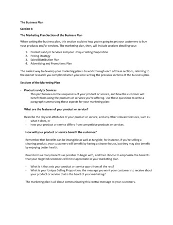
CHAPTERThree-View, Plan Viewand Elevation View DrawingsTechnical drawings are the language engineers andarchitects use to communicate their ideas and designsto journeymen. It is a language based on lines and s:mbols that have specific meanings. Journeymen mustpossess the sldll to interpret these symbols and l i e s ,so that they may install and maintain piping systems.This chapter discusses the use of three-view drawings, section drawings, and schematic drawings, andintroduces some special-purpose drawings, such as exploded drawings and wiring diagrams.The photograph in Fig. 2-1 clearly depictsthe over-all appearance of a concreteblock. A three-view drawing will mostclearly show the appearance as well asthe exact size and other details ofconstruction of an object.Top ViewFront ViewRight-Side ViewAlso, the Right-Side View in Fig. 2-2 does not represent what is usually considered the "Right-Side" of theconcrete block.The key to understanding the relationship of theviews in a three-view drawing is the Front View. TheFront View locates the object directly in front of theviewer. See Fig. 2 3 .The three-view drawing of the concrete blockshown in Fig. 2-2 is a drawing with the Top View positioned directly above the Front View and the RightSide or Left-Side View positioned directly to the rightor left of the Front View.'3:-1The Front View of the concrete block in Fig. 2-2does not show what is normally considered the FrontView.The Front V ewin a 3 View drawing does not necessarily show the -front" of an object
How, then, is the Right-Side View relatedto the Front View?Fig. 2-6 is a three-view drawing of aconcrete block.With the Front View directly in front of the viewer,the Right-Side View is what the viewer would see if heor she were to walk to their right until the right side ofthe object was directly in front of them. See Fig. 24.-Top ViewFront ViewRiqht-Side View11 1Front ViewB1R ght-SldeV ewHow would the Top View be related to theFront View?The TOP View in Fig. 2-5 shows the object a s theviewer would see it when they stand at the Front View, asshown in Fig. 24, and look directly down on the object.TOP ViewOn squared block Paper, sketch theconcrefe block in three views as shown infig. 2-6. usea straight edge and amedium-weight pencil. Note the equalspacing at "A" and "6."Save thesesketches for future reference.The drauing in Fig. 2-6 does not give a complete understanding of the object. Only the visible details ineach view are shown.In a three-view drawing, solid limes are used to represent the details of an object which can be seen ineach view.Broken lines are used to illustrate the openingswhich are "hidden" in the Front and Right-Side Views.See Fig. 2-7.
rnnrr-vrrw,1-LAN V l L W AND ELEVATION VIEW DRAWINGS3rTOPViewFrontViewTOPViewRight SideViewUsing the Top View shown in Fig. 2-8 asthe Right-Side View, make a secondsketch and compare it with Fig. 2-9.The three-view drawings which havebeen discussed are generally accepted asstandard in the United States andTOPView;,The Front View, Top View, and the RightSide View in Fig. 2-7 must be comparedto get a true picture of the "hidden"details.IOn squared block paper, make a threeview drawing of the concrete block withthe Front View being what is normallyconsidered as the front of the block.Compare your drawing with the oneshown in Fig. 2-8.FrontViewRight SideView
Canada, but other views may be shownwhich would better illustrate the object.See Fig. 2- 10.TopViewIThe water closet shown in Fig. 2-11 istaken from an actual rough-in book.The Front View of the drawing in Fig. 2-11shows theleft side of the fixture.In Fig. 2-11, the left side of the fixture was chosen asthe Front View because the left side of the fixture contains the ballcock and the rough-in could best beshown by this view.The Top View- of the fixture in Fig. 2-11 was omittedbecause the Front View, Right-Side View, and relatednotes provide sufficient information to rough-in thisparticular type water closet.Technical drawings don't always showthree views or all of the hidden lines andthe exact outside shape of an object.FrontViewRight SideViewIf space is at a premium, the draftsman may usesymbols to represent objects such as valves or pipe fittings.Finished Wall LineY8'' S.P.S. Supply to FloorWhen SpecifiedNOTE: This Water Closet is Designed to Rough-in at a Min. Dimension of 12" From Finished Wall to Q of Outlet
Fig. 2-12-A, B and C are drawings of a 90"elbow shown in three views. An exampleof a 90" elbow is shown in Fig. 2-12-6 andC using symbols.Tee Looking Away From Viewer1@QTop ViewTop ViewAFrontViewCheck ValveRight SidViewFrontViewr1Right SideViewQPDTop ViewFrontViewReducer or IncreaserTee Looking Toward ViewerRight SideMewCOn squared block paper, sketch a threeview drawing, using fitting symbols, toillustrate the piping arrangement shownin Fig. 2-15.In the process of making a drawing of acomplicated piping system, the use ofsymbols similar to the types shown in Fig.2-13 obviously saves time and space. Youmust know what these symbols stand forif you are to understand what thedraftsman is trying to convey in a drawing.IEach symbol in Fig. 2-13 is both correctly identifiedand pictured by a double line drawing in Fig. 2-14.Compare your sketch with the one shown in Fig.2-16.17
Note: The "Fitting Face Marks" are omitted in Fig.2-16.0Fitting Face Marks should only be used on a sketchor drawing when they are needed for clarification.Figs. 2-17, 2-18 and 2-19 are the front, right side, andtop views of a pneumatic water booster system. Fig. 220 is the same system drawn in an isometric view withthe use of fitting symbols.Symbols are used in Fig. 2-20 which represent thepumps, valves and fittings. From observation it becomes obvious that the use of symbols require far lesseffort than drawing each item in the three views of thepneumatic water booster system shown in Figs. 2-17,218 and 2-19.
THREE-VIEW, PLAN VIEWANDELEVATION VIEW DRAWINGS
THREE-VIEW, PLAN VIEWANDELEVATION VIEW DRAWINGS
as vessels, turbines, etc. You must remember that thisview is from the bottom looking up.The type of drawings most commonlyused on job sites are plan and elevationviews. Usually the plan and oneelevation view are used to fully describean object, however in some instancesmore than one elevation view is needed.Explain.The plan view is often used to show the floor plan ofa building or equipment room. Usually the plan viewshows the building with the roof removed and the observer is looking down at the floor or floor plan.The plan view is the view as seen from above the object, looldng down on it or the top view.Fig. 2-21 shows the correct method forarranging these six views. When sketchingpipe, how should these rules be observed?The elevation view is the view from one side of theobject. Fig. 2-21 is an example of this type of drawing,showing the plan view, four elevation views and thebottom view.1. The top view or plan view should be placed directly above the front view.Each one of these views shows two of the principledimensions and can show only two. The front view orfront elevation shows the width and height of the frontof the object. The top view or plan view shows thew i d t h and length of the top.3. The right view should be drawn directly to theright of the front view.The right side view or right elevation shows thelength and height of the right side. The left view or leftelevation shows the length and height of the left side.The rear view or rear elevation shows the w i d t h andheight of the rear side.The bottom view is not a plan view, but rather it is aview from beneath the object looking up. This viewshows the length and width of the underside of the object. This view is not often used in pipe drawings, but issometimes used to show the bottom side of such things2. The bottom view should be drawn directly belowthe front view.4. The left view should be drawn directly to the left ofthe front view.5. The rear view should be drawn to the left of the leftview or if necessary to the right of the right view.While some views can be omitted: no view should bedrawn in any other position.Fig. 2-22 is a pictorial drawing of a simple piping situation using screwed pipe and fittings with the fittingsnumbered and the pipe lettered. To give a complete description of this piping situation using a plan and elevation view, at least lwo views a s in Fig. 2-23 would Elevation
3The symbol used to show the tee is the symbol for atee turned up or side outlet up. You b o w from the planview that the side outlet of the tee is horizontal. Thissymbol shows that you are looking into the side outletor the side outlet is facing you.33Fig. 2-24 shows the five views possible for t h epiping situation in Fig. 2-22. The bottom view is notused.Rear ElevationIPlanPlanRightLeftElevationFront ElevationStarting at the left side of the plan view you well seethe symbol for the 90-degree ell n t u r n e d doum. Fromthis ell going to the right, you will see nipple @ whichThe side outlet of the tee is in theconnects to teehorizontal position with a piece of pipe @) screwedInlo l r On thr right s d cof the te? 15 another plecc ofpipe @ whlvl connects to a 90-degr? ellturnedUP.ElevationIFront ElevationA.-1This plan \view shows most of the informationneeded, but not all of the information needed. It doesTo getnot show the length of the nipples @ andthese lengths you must refer to the front elevation viewin Fig. 2-23.0.Scarting at the left side of thesee nipple @ connected to theis now shown as a side view. Moving to the right fromyou can see nipple@, which isthe 90-degree ellconnected to IIA.To be able to draw the four elevation views youmust rotate the pictorial drau-ing in Fig. 2-26 in yourmind's eye. If this were a piping situation alreadyfabricated it would be simple to walk around to therear side to see how it looks, but most drawings o rsketches are made to show how the pipe is to befabricated rather than t o show existing pipe fabrications.
Fig. 2-25 is a pictorial drawing with the fittings numbered and the pipe lettered. Fig. 2-26 consists ofa plan and four elevation views of the same piping situation.Study the pictorial drawing in Fig. 2-25. Fill in the correct numbers in the triangles next to each f i i n gin the plan and elevation views in Fig. 2-26. Fill in the correct letter in the square next to each pieceof pipe.In Fig. 2-26 which elevation view would be the best one to use?0loRear ElevationPlan ViewFrontFront ElevationeftElevationRightElevation
.nrr- wlrw, I'LAN VIEWAND ELEVATIONVIEW DRAWINGSDraw the plan view and fmnt elevation view of the piping situation in Fig. 2-27 on a piece of squaredblock paper. Use a drawing board and T-Squae. Use screwed fitting symbols. Make the drawingapproximately twice the size shown in Fig. 2-27.)The terms front elevation view, rear elevation viewand side elevation view refer to the side from whichyou are viewing the object. When drawing the front elevation view of a building, this would be the view wherethe journeyman is standing in front of the building andlooking at the front.The terms front, rear, and side are not often used inpipe work, especially in industrial applications. Theseterms are replaced by the terms east elevation, west elevation, north elevation and south elevation.The front view of a building would be called thesouth elevation view as shown in Fig. 2-28.Soulh ElevationWest Elevation
Fig. 2-29 shows a pictorial view of a cylinder and athree view drawing of the same cylinder. Piping diagrams normally use the points of the compass to de-scribe the elevations. Note that the South Elevation isthe south side of the tank and would be seen when youare facing north.-PlanSouth ElevationEast Elevation----
iiThe elevation views of piping w o u l d be named in thesame m a n n e r Fig. 2-31 shows the plan view and thefour elevation views o f the piping anangement in230.- rsWest Viewfrom thissideDownNhhSouthViewIEast Viewfrom thissideIPlan ViewFEast ElevationSouth Elevation -3West ElevationNorth ElevationFig.
EXERCISE 2-3On squared block paper draw a Plan View and East Elevation View of the piping arrangement in Fig.2-32."XISDraw a Plan View and West Elevation View of Fig. 2-33.DownDown
CHAPTERGraphic Symbols forPipe Fittings and ValvesThe use of symbols to represent fittingsand valves on pipe drawings andsketches is necessary to show whattypes of fittings and valves are to beused. Without the use of these symbolsthe fittings and valves would have to bedrawn to their actual shape or their typeswould have to be written on the drawing.What has the piping industry done toshow the types of fittings and valves tobe used?The piping industry has developed a set of symbolsto represent pipe fittings and valves. Most of thesesymbols are universal and the most common onessuch as the standard symbols shown in Fig. 3-1 forGate Valvegate valves, globe valves, and check valves are recognized throughout the industry. Some of the larger companies and some localities have their own symbolswhich they prefer to use, and this should be kept inmind.Pages 31 through 37 show single-line graphic symbols as currently used in the piping industry. Whendrawing these symbols it is not necessary to attempt toscale the size of the symbol to correspond with the sizeof the valve or fitting represented. There is no rule reg.ulating the size of these symbols. They must be largeenough to permit easy and accurate reading.Representation of single-line symbols may be compared to letting a single wire represent the pipe, andrepresenting the connection of the pipe to the fitting bya disc centered on the wire (in the case of flanged fittings, two discs). See Fig. 3-2. This assembly whenAngle Gate ValveFrontLeftTOPGlobe ValveAngle Globe ValveCheck ValveAngle Check ValveRightPictorial view of discs representing screwed fittings
viewed from the top, front, or either end will give theappearance of a single-line symbol representing the fittings shown in Figs. 53 through 56.Why are fitting face marks currently used less in single line drawings than in yearsprevious?With the advent of "fast track" jobs, CAI) (computeraided drawing), and the need to save time; fitting facemarks are often omitted.Front view of fittingsThe symbols used to indicate the joining methods(such as welded, flanged, soldered, etc.) and the pressure rating of the fittings required in a piping systemare also often omitted from drawings. The journeymanmust refer to notes on the drawing, the job specifications, and the addenda in order to be sure of the typesof inaterials to be used for each system.Most charts refer to the position of thesymbols as "in elevation, turned up, orturned down." In elevation means a viewlooking at the side of the symbol. Listfour examples of the position of symbolsfor fittings shown in a front view, left sideview, right side view and top view in apiping drawing.Left side view of fittingsWith the elbow or with the tee, the discs would appear as stmight lines as in Fig. %3. These cross lines onthe symbols are drawn so they appear to be lying in theplane formed by the bend in the pipe. When symbolsoverlap, the rear or overlapped symbol is usually omitted.If the elbow is tumed so the flow is away from theviewer (viewed from the left), one of the connectingdiscs would appear as a circle and the back of theelbow would appear as a line drawn to the center ofthe disc. See Fig. 54. The tee would appear as shownwith the circle, dot, and line.Right side view of fittingsIf the elbow is turned so the flow is toward theviewer (viewed from the right), one connection wouldappear as a circle, the other as a straight line. The endof the pipe would be shown as a dot in the center of thedisc, as shown in Fig. 2-5.Fig. 3-6 shows the appearance of the elbow and teewhen they are viewed from above.TODview of fittinasSee Table 3-A. Provide a complete list ofgraphic symbols for pipe fittings andvalves. Construct the list in table formwhich will include symbols for fittings andvalves with flanged, screwed, bell andspigot, welded and soldered joints.
GRAPHIC SYMBOLSi1. BUSHING3.1 REDUCING4. CROSSOVER5 1 45-DEGREE5.2 90-DEGREE5.3 TURNED DOWN OR5.6 DOUBLE BRANCH31FORPIPEFIITINGS AND VALVES
-.TABLE 3-A (continued). GRAPHIC SYMBOLS FOR PlPE FIlTINGS AND VALVESFLANGED5.7 LONG RADIUS5.8 REDUCINGg J :OUTLETzV&5.9 SIDEYOU)pTfi6.2 EXPANSION7. LATERAL8. ORIFICE FLANGEWELDEDISOLDEREDrII4--1(fd-I-i, -I.LFE- -- k - - c - - *G;I4-1' " ffSTREET6. JOINT6.1 CONNECTINGPlPEBELL 8 SPIGOTfl p- 5.10 SlDE OUTLET(OUTLETUPORTOWARD YOU)5.11SCREWEDeP Y YC-L:I-.--LL.I-.- IF-!?9. REDUCING FLANGE---(iE32
i- -10.1 BULL PLUG10.2 PIPE PLUG11.2 ECCENTRIC112.SLEEVE13.TEE13.1 STRAIGHTSIZE3 - - L L L13.2 OUTLET UP ORTOWARD YOU 13.3 OUTLET DOWNOR AWAY FROMYOUtl i -t13.4 DOUBLESWEEP13.5 REDUCING13.6 SINGLESWEEP@,n/2 U Lt b t IJ-#&&b--AnA,wVuV2 S t 4 .&@
TABLE 3-A (continued). GRAPHIC SYMBOLS FOR PIPE FITTINGS AND VALVESFLANGED13.7 SlDE OUTLETAWAY FROM YOU--.- ---- -.SCREWED&I.-BELL & SPIGOTWELDEDSOLDERED,X:;-&&13.8 SlDE OUTLETTOWARD YOU- IF --I 14. UNION.- . (I--. i"f15. ANGLE VALVE15.1 CHECKi l l 15.2 GATE(ELEVATION)at-( 3 315.3 GATE(PLAN)(33-p a ,at15.5 GLOBE(PLAN)-- 15.6 HOSE ANGLE 16. BUlTERFLYVALVE--SAME AS El-ED-. .--SYMBOL23.1
TABLE 3-A (continued). GRAPHIC SYMBOLS FOR PIPE FllTlNGS AND VALVESFLANGED17. BALL VALVE18. STRAINERSCREWEDBELL & SPIGOTWELDEDSOLDEREDiloc -lot-4ok*# 19. CHECK VALVESAME AS19.1 ANGLE CHECK19.2 (STRAIGHT WAY)SYMBOL trdl-w-**20. COCKi nit-21. DIAPHRAGM& AVALVE15.1r-2L-2f16 81-3.&&r -ri1r -1I.:0L-,I22. FLOAT VALVE&&23. GATE VALVE o c t - r a - -.23.l23.2 ANGLE GATE23.3 HOSE GATESAME ASSYMBOLSSAME ASSYMBOL15.2& 15.323.2'ALSO USED FOR GENERAL STOP VALVE SYMBOL WHEN SPECIFIED.:--IL-2I
24. GLOBE VALVE24.4 MOTOR-OPERATED25. HOSE VALVE25.1 ANGLE25.2 GATE-HXb a25.3 GLOBE a--b 26. LOCKSHIELD VALVE&&27. QUICK OPENING VALVE-i%--&GbGb28. SAFETY VALVE29. STOP VALVE&- # a - * m @ - SAME ASSYMBOL21.1
GRAPHIC SYMBOLSFORPIPE FITTINGSANDVALVESTABLE 3-A (continued). GRAPHIC SYMBOLS FOR FLANGED AUTOMATIC VALVES30. AUTOMATICVALVE30.2GOVERNOROPERATED30.1 BY PASS9qr30.3REDUCING-4IFig. 3-7 shows a piping installation drawnwith the two-line method. It gives acomplete picture of the pipe, valves andfittings. What method is used in Fig. 3-8which shows the same piping installation?Fig. 58 shows the same piping installation as shownin Fig. 5 7 , however the single-line method is used to r e present the pipe and the proper symbols are used to represent fittings and valves. The fittings and valves in Fig. 5 7and Fig. 58 are numbered and the pipe is lettered.Study and compare both drawings for abetter understanding of piping symbols.A comparison of these two drawings illustrates thesimplicity of the single-line type of drawing. Both drawn show the same pipingings. . - installation, but the singleli e drawing is the easiest one to draa. and the morepractical one to be used in the field.-7
-Following are five exercises which require you to identify symbols for several types of valvesand pipe fittings. Read the directions and furnish the correct information in each exercise.EXERCISE 3-1Fill in the correct names of the fittings and valves shown in Fig. CISE 3-2Fill in the proper name of the symbols.-!I
GRAPHICSYMBOLS FORPIPE FITTINGS ANDVALVESDraw or sketch the proper symbols in the spaces provided.NOTE: The symbols may be drawn with straight lines ratherthan curved lines; for example, a 90degree screwed ell may be drawn:TeeStraight SizeSolderedUnionScrewedCheck ValveBell and SpigotGate ValveScrewed90" ElbowTurned UpWelded90' Street ElbowScrewedLateralFlangedConcentric ReducerWeldedGate ValveFlangedGlobe ValveScrewedTeeOutlet DownFlanged90" ElbowTurned DownWeldedTeeOutlet UpScrewedCrossStraight SizeScrewed45" Elbow90" ElbowSolderedSoldered
EXERCISE 3-4Add the proper symbols to this drawing using the symbols for screwed fittings.45"Ell-GateValve-90'Ell-
U K A l ' H l L 3 Y M b U L S t U K I'I1'L T I 1 IINCIS AND VALVLSCircle t h e number next t o the correct answer.1.In this top view the elbow is turned:1. up or toward you.2. down or away from you.2.This is a side view or elevation view of the same piping configuration as in Question 1. The elbow is a:1. 90' soldered ell.2. 45' street ell.3. 90" screwed ell.3. In this top view there are two fittings. They are:1. two 90 weld ells.2. one weld and one screwed 90' ell.3. two 90' screwed ells.4.This is a side view (elevation view) of the piping configuration in Question 3. Elbow "A" is looldng:I. toward you.2. away from you.
-EXERCISE 3-5 (continued)5. In this top view elbow "A" is turned:1. up.2. down6. This view shows apiping comigwxtion with two 90' ells. The ells are:1. both turned up.2. one is looking up and one is turned down.7. This is an elevation view (side view) of the same piping confi-on1. turned away from you.2. turned up.3. turned toward you.8.What kind of fittings are shown in this piping diagram?1. screwed.2. soldered.3. flanged.4. welded.QIshown in Question 6. Elbow "A" is:-!
CHAPTERInterpretation ofTechnical DrawingsWorking drawings convey information about theconstruction of a building to the builder. These drawings try to give a three-dimensional view of the building. Orthographic and isometric drawings and mechanical plans make up the working drawings. Journeymenmust interpret the working drawings to install the piping systems properly.Orthographic drawings view a building by lookingdirectly at the front, top, and side of it. These views aredrawn to scale. All lines are true lengths and angles arenot distorted.Orthographic drawings are made of the elevations,floor plans, section views, and detail drawings of abuilding. Elevations show the front, rear, and side exterior views of the building. By passing a horizontalcut midway between each floor, a plan view orfEoorplan is seen. This cut passes through all doors, windows, and wall openings to show the room as it appears when looldng directly down on it. If a verticalcut is made through the building, then a section viewis shown. Section views show the interior of the building from the foundation to the roof when looking directly a t its side. Since all views are drawn to scale,certain building features may be too small to see itsconstruction.The Side and Front Views of a buildingare usually called "elevations" andnoted as North, South, East, or West.What is the relationship between theNorth Elevation of a building and theviewer?In order to \leu- the North Elevation of a building,the viewer must be positioned in front of the north elevation facing South.The West Elevation in Fig. 4-1 is elevation A,If the interior (imisible) details of an object are relatively simple, such as in the example of the concreteblock; they can be represented by a series of shortdashes (a broken line). A section drawing is usedwhere the ntemalfeatures are compl catedand moredeml IS necpssaryTop View8A section drawing is a "cut-away" view ofan object. What is the function of line AAin Fig. 4-2?Line AA in Fig. 4-2 indicates the cutting plane(where the object is to be cut away) for a section. SeeFig. 4-3.-
PlanThe diagonal lines in Fig. 4 6 represent the solid portions of the object and the material of which it is made.The line at Point A indicates the center line and isused to show the center axis of the shaft. In pipingdrawings, center lines are important because most piping measurements are taken to the center of a pipe,valve or fitting.IBOn sauared block paper, make a sectiondrawing of the object shown in Fig. 4-4and compare your sketch with Fig. 4-5.PlanIJThe horizontal l i e at point B in Fig. 4-6 shows theshoulder formed when the diameter of the drilling wasdecreased.An object familiar to Journeymen in the pipe tradesis shown in Fig. 4 7 . The section drawing in Fig. 4-'provldes you with a complete descnpuon of the deuof construction of a rypical catch basin.
Dimension A in Fig. 4 7 is taken from the invert elevation of the pipe to the top of the cast iron grate at elevation 169.5'.The invert of a pipe is the lowest portion @ottom)of the inside of a horizontal i o eThe.invert elevationof the pipe in Fig. 4-7 is 167.0'.A What is the distance from the invert ofthe 10"drain to the top of the cast ironcatch basin grate in Fig. 4-7?Top of Grate ElevationInvert Elevation of 10" pipeDimension A 169.5'167.0'2.5' or 2 ' 4 "The distance is 2.5' or 2'- 6The tmes of materials to be used in the constructionof the catch basin in Fig. 4-7 are shown a s architecturalsymbols in this section drawing.There are five types of material illustrated by architectural symbols in Fig. 4-7. The five types of materialsare concrete, mortar cement, brick, cast iron and concrete pipe.:Fig. 4-8 is a section drawing of a pressure reliefvalve. (See 'Architectural Symbols" in the referencesection at the end of this book.) It has been determinedfrom the list of "Architectural Symbols" in Appendix Athat the body of the valve is constructed of cast iron,In addition to the use of architectural symbolswhich identify materials to be used for construction ofan object or building, the notes on a drawing and relared specficarions must be e x m n e d to dererrnlne thespecific types of materials which will be requiredi
Why are the two sets of lines drawn indifferent directions if both the top of thevalve body and the bottom are made ofcast iron? See Fig. 4-8.By changing the direction of the lines, the draftsmanhas indicated that these parts are separate and can bedisassembled at the point of the change. The draftsmanhas also indicated by use of arrows at points A, 6 andC, that there is a spring at point A, internal threads atpoint 6 and external threads at point C.A section drawing of a gate valve with solder jointends is shown in Fig. 49. Architectural symbols werenot used to show the materials of construction becausethey would make the drawing more confusing.The types of materials of construction are Listed inthe Table of Specifications in Fig. 49. A description ofthe numbered parts of the gate valve are also listed inthe Table of Specifications.Part number 9 in Fig. 4-9 is the packingnut. What is the packing nut made of?The packing nut is made of bronzeThere are drawings other than three view and section drawings which Journeymen must be able to interpret, such as schematic drawings. A schematic drawingis a diagram of a system without regard to scale orexact location.Schematic drawings can be used as riser diagrams,stack drawings, and special drawings similar to thoseshown in Figs. 410 th ough415.A riser diagram of the water piping for aresidence is shown in Fig. 4-f0. What isshown on riser diagrams?Riser diagrams indicate sizing, offsets, branches,and the floor or location at which they occur.TABLE OF SPECIFICATIONS
Fig. 4-11 is a schematic drawing of a domestic hot water heating systemThe location of the equipment to be installed cannot be determined from the drawing in Fig. 4-11. The valves,equipment and a large majority of the fittings can be listed from the schematic diagram. H o e v e rsince,location orthe scale of the drawing is not shown, the exact amount of pipe and fittings cannot be determined.Sketch the schematic drawing shown in Fig. 4-11 on squared block paper and compareyour drawing with Fig. 4-1 1.WATER HEATER C ' 1 G R A Mr"0 SCALEThe purpose of the schematic diagram of the evaporation cycle shown in Fig. 4-12 is to show the direction of flow,the sequence of operation of the equipment, and the resultant temperatures.Ternp atu1e01 W a OYIiCandenser150'Llqvld Fmm Condenser
Even though the arrangement of the piping andequipment can be determined from Fig. 4-12, it is sN1not possible to list all of the fittings needed to installthe piping system. The major fittings and equipmentcan be listed from Fig. 4-12, but since the actual location is not shown, the number of fittings and the exactamount of pipe cannot be determined.Fig. 4-13 is an "exploded view" diagram of a ballvalve. Exploded view diagrams are primarily used forassembly, disassembly, parts replacement, maintenance, and trouble-shooting of equipment. Explodedview drawings and diagrams are usually included in theoperation and maintenance manuals provided withequipment delivered to the job site.The numbers on the drawing in Fig. 4-13 indicate theorder of disassembly of the ball valve. The numbersalso identify the numbered part when they are keyed toa specification sheet which is usually part of the operation and maintenance manual provided with the equipment.The name of the part shown as number 7 in Fig. 4-13is "iron pipe size body end." The model number, partnumber, and correct size can be identified from thespecification sheet and must be given when orderingreplacementparts.ContainsValve Par( No, 8 Description1. Handle Nut2. Handle for -W valve (Buna-N seat)2a. Handle for -Y valve Fellon seat)3. Packing Gland4. Stem5. Bodyfi-.Rail7. IPS Body end73. Solder Body end8. Body Nuts .3 Bolts (per set)9. Seat 8 Seal Kit for -W valve(Buna-N seat)2 4 u n a - N seats2--6una-N body seals1-Teflon thrusl washerl-Teflon stern packing9a. Seat 8 Seal Kit lor -Y valve(elolnseat)Contains2-Teflon seats2- PDM body sealsI-Teflon thrust washerl-Teflon stern packing
The diagram in Fig. 4-14 is used to show the types ofwelds which are required for each of the two piping applications.The symbol at Point "B" in Fig. 4-14 requires thewelds at these locations be fillet welds, and that theybe welded "All-Around."Heavy Tee Finings Outdoor LayoutA wiring diagram is shown in Fig. 4-15.When are wiring diagrams useful to pipetrades journeymen?Wiling diagrams are useful in locating the cause oftrouble in a piping system which includes electrical devices.with S@cific
A three-view drawing will most clearly show the appearance as well as the exact size and other details of construction of an object. The three-view drawing of the concrete block shown in Fig. 2-2 is a drawing with the Top View