Transcription
INSTALLATION OPERATION.comI.B. 46-100-lA MAINTENANCEualsINSTRUCTIONSanOil-ImmersedtMDIS TRIBUTIONlParTRANSFO RMERSTYPEScaCSP- Completely Self-ProtectedCP- Current ProtectedlectriS- Conventional15,000 Volts or LessSingle- and Three-Phasewww.E3 to 167 KvaSB- Shovel (Special Braced)WESTINGHOUSE ELECTRIC CORPORATIONSHARON, PA. TRANSFORMER DIVISION SUNNYVALE, CALIF.MAY, 1954SUPERSEDES 1.8. 46-100-1 AND SUPPLEMENT "A"(Rep.6-57)Printed in U.S.A.
Pages 6-8DESCRIPTIONPart O neApplication . . . . . . . . . . . . . . . . . . . . . . . . . . . . . . . . . . . . . . . . . . . . . . . . . . . . . . . . .Component Parts . . . . . . . . . . . . . . . . . . . . . . . . . . . . . . . . . . . . . . . . . . . . . . . . . . . . .9Preparation for Installation . . . . . . . . . . . . . . . . . . . . . . . . . . . . . . . . . . . . . . . . . . . . .9Parallel Operation . . . . . . . . . . . . . . . . . . . . . . . . . . . . . . . . . . . . . . . . . . . . . . . . . . .Protective Link Coordination ("CSP" Transformers Only) . . . . . . . . . . . . . . . . .Fusing Practices ("S" Transformers Only) . . . . . . . . . . . . . . . . . . . . . . . . . . . . . .IIan.Mounting . . . . . . . . . . . . . . . . . . . . . . . . . . . . . . . . . . . . . . . . . . . . . . . . . . . . . . . . . . . . . . . . . . . . . . . . . . . . . . . . . . . . . . . . . . . . . .ar.tMBushing Arrangement . . . . . . . .High Voltage Connections . . . . .Low Voltage Connections . . . . . .Tank Grounding Connections . .lPcaTransformer Proper . . . . . . . . . . . . . . . . . . . . . . . . . . . . . . . . . . . . . . . . . . . . . . . . . .Lightning Protection ("CSP" Transformers). . . . . . . . . . . . . . . . . . . . . . . . . . .Burnout Protection ("CSP" and "CP" Transformers) ."LR" Breaker . . . . . . . . . . . . . . . . . . . . . . . . . . . . . . . . . . . . . . . . . . . . . . . . . . . . . ."BR" Breaker . . . . . . . . . . . . . . . . . . . . . . . . . . . . . . . . . . . . . . . . . . . . . . . . . . . . . ."FR" Breaker . . . . . . . . . . . . . . . . . . . . . . . . . . . . . . . . . . . . . . . . . . . . . . . . . . . . . . .Service Control Device . . . . . . . . . . . . . . . . . . . . . . . . . . . . . . . . . . . . . . . . . . . . . . .Protective Links . . . . . . . . . . . . . . . . . . . . . . . . . . . . . . . . . . . . . . . . . . . . . . . . . . . . .Part FourTapslectri.I3I5I5.I8I820.27.22273030Pages 31·36OPERATION AND MAINTENANCE.IIIIIII3Pages 18-30PRINCIPLES OF OPERATIONPart Three.3I3I3I33.ECircuit Breaker Manual Operation . . . . . . . . . . . . . . . . . . . . . . . . . . . . . . . . . . . .Signal Lights . . . . . . . . . . . . . . . . . . . . . . . . . . . . . . . . . . . . . . . . . . . . . . . . . . . . . . . . .Circuit Breaker Tripping .Circuit Breaker Tripping Adjustment . . . . . . . . . . . . . . . . . . . . . . . . . . . . . . . . . .Circuit Breaker Operating Linkage Adjustment . . . . . . . . . . . . . . . . . . . . . . . . . . .333334Maintenance . . . . . . . . . . . . . . . . . . . . . . . . . . . . . . . . . . . . . . . . . . . . . . . . . . . . . . . . .3636wService Control Device . . . . . . . . . . . . . . . . . . . . . . . . . . . . . . . . . . . . . . . . . . . . . . .Renewal Parts . . . . . . . . . . . . . . . . . . . . . . . . . . . . . . . . . . . . . . . . . . . . . . . . . . . . . . . .ww67Pages 9-17INSTALLATIONReceiving, Handling and Storing . . . . . . . . . . . . . . . . . . . . . . . . . . . . . . . . . . . . . . . .26ualsOperating Limits . . . . . . . . . . . . . . . . . . . . . . . . . . . . . . . . . . . . . . . . . . . . . . . . . . . . .Part Two.comTABLE OF CONTENTS
.comI .B. 46-100-lADISTRIBUTION TRANSFORMERSLIST OF 1617181920212223242526272829ca1112Cutaway View of Typical Wall Bushing "CSP" Transformer. . . . . . . . . . . . . . . . . . .Cutaway View of Typical Cover Bushing "CSP" Transformer . . . . . . . . . . . . . . . . . .Typical Three-Phase Transformer. . . . . . . . . . . . . . . . . . . . . . . . . . . . . . . . . . . . . . . . . .De-ion Arrester Assembly and Gap Adjustment . . . . . . . . . . . . . . . . . . . . . . . . . . . . .Protective Link Current Time Curves. . . . . . . . . . . . . . . . . . . . . . . . . . . . . . . . . . . . . . .Pole Mountings for Distribution Transformers . . . . . . . . . . . . . . . . . . . . . . . . . . . . . . . .Three-Phase Connection of Standard Single-Phase Transformer . . . . . . . . . . . . . . . .Transformer Class Designations. . . . . . . . . . . . . . . . . . . . . . . . . . . . . . . . . . . . . . . . . . .Externally Mounted "De-ion" Lightning Arrester and Gap Adjustment . . . . . . . . . .Combined Single-Phase, 3-Wire Load and Three-Phase Load on "CSP" Trans former (Use Open Delta Connection Omitting Dotted Transformer) . . . . . . . . . . . . .Mechanism of "Three-Point Surge Protection" . . . . . . . . . . . . . . . . . . . . . . . . . . . . . .Curves Showing that Thermal Protection of Distribution Transformers by Fusesis Unsatisfactory . . . . . . . . . . . . . . . . . . . . . . . . . . . . . . . . . . . . . . . . . . . . . . . . . . . . . . . .Connection to Utilize Two Circuit Breakers for Larger "CSP" Transformers . . . . . .Cutaway View of "LR" Circuit Breaker. . . . . . . . . . . . . . . . . . . . . . . . . . . . . . . .Schematic Operational Sketches of "LR" Circuit Breaker . . . . . . . . . . . . . . . . . . . .Cutaway View of "BR" Circuit Breaker. . . . . . . . . . . . . . . . . . . . . . . . . . . . . . . . . . .Schematic Operational Sketches of "BR" Circuit Breaker . . . . . . . . . . . . . . . . . . . . .Cutaway View of "FR" Circuit Breaker. . . . . . . . . . . . . . . . . . . . . . . . . . . . . . . . . . .Schematic Operational Sketches of "FR" Circuit Breaker . . . . . . . . . . . . . . . . . . . . .Emergency Control Handle in Normal Position . . . . . . . . . . . . . . . . . . . . . . . . .Emergency Control Handle in Emergency Position . . . . . . . . . . . . . . . . . . . . . . . . . . ."FR" Breaker Tripping Adjustment . . . . . . . . . . . . . . . . . . . . . . . . . . . . . . . . . . . . . . . .Typical Breaker Trip Curves Showing Effects of Emergency Control . . . . . . . . . . . ."BR" Breaker with Manual Operating Mechanism and Emergency . . . . . . . . . . . ."LR" Breaker Operating Handle, Linkage, and Signal Light . . . . . . . . . . . . . . . . . . ."BR" Breaker Operating Handle, Linkage, and Signal Light . . . . . . . . . . . . . . . . . ."FR" Breaker Operating Handle and Linkage. . . . . . . . . . . . . . . . . . . . . . . . . . . . . . .Method of Mounting Control Device When Above Fins. Also Parts List . . . . . . . . .Method of Mounting Control Device When Above Hanger Lugs . . . . . . . . . . . . . .tri12345678910Page3
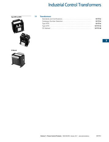
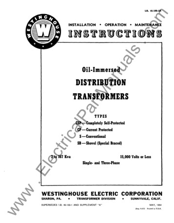
.comualsantM"CSP" Transformer withtwo Wall Bushings.ElectricalPCover-Mounted Bushingsar''CSP" Transformer with twowww''S'' Conventional Transformer4(167 Kva)3 Phase "CSPB" Transformer ith Wall Bushings
uals.comI .B. 46-100-lADISTRIBUTION TRANSFORMERSOil-ImmersedanDISTRIBUTION TRANSFORMERSartMThis instruction book has been prepared to assist the purchaser in properlyinstalling, operating and maintaining the oil-immersed distribution transformerssupplied by Westinghouse. The methods and recommendations presented arebased on the best practical judgment of Westinghouse engineers, from theirexperience in design and installation of this apparatus and the reports ofexperience from purchasers of similar or related apparatus.www.ElectricalPThis book applies to all standard and most special transformers. However, itmust be recognized that a publication of this type cannot cover exact construc tion details of all possible voltage and kva ratings and all other modificationswhich may be furnished on special orders. The information contained hereintogether with the data appearing on the nameplate attached to the transformer,and on the connection diagram if specified on the nameplate, should permitsatisfactory operation of the transformer.5
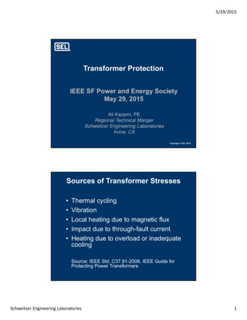
.comPA RT ONEDES CRIP TI ONualsCOMPONENT PARTSOil-immersed distribution transformers consistessentially of: (1) a closed-loop magnetic core uponwhich is wound two or more separate copper coils;(2) a tank for containing the insulating and coolingoil in which the core-coil assembly is immersed; (3)the necessary bushings for bringing incoming andoutgoing leads through the tank or cover.tMOil-immersed distribution transformers are nor mally used for stepping public utility "distributionvoltages" (ranging from 2400 to 15,000 volts) downto lower utilization voltages. By far the greatestquantity are used for stepping down to a householdvoltage of 120/240 volts although a few are used forstepping down to industrial voltages of 240/480,600,or 2400 volts. These same transformers are some times used for small substations and for miscel-laneous applications. As with any transformer, theycan also serve as step-up units.anAPPLICATIONVOLTAGEBUSHINGarH.V. BUSHING LINElPLIFTING1---- CIRCUIT B{tEA KEREXTERNAL f:fANOLEAND SIGNAL UGH TcaH.Y. TAP CHAN GEF ---HANDLEEMERGENCY CONTROl.HANDLE ON FAR SlOEOF BREAKER HANDLECIRCUIT BREAKEROPERATING ROD.V. PROTECTIVE LINK-.ww6FIG. I.CORESTRUCTION PLATE ------- TANKw.ElectriH.V. TAP CHANGERDIAL PLATECutaway View of Typical Wall Bushing "CSP" Transformer.
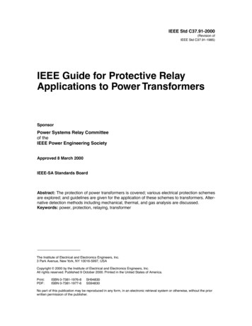
.com·· 8 · 46- 10 0- lAD ES C RIPTION ----------------------------------- DISTRI BUTION TRANSFORMERSH.V. DE-ION ARRESTERualst-.---H.V. DE-ION ARRESTER(SECTIONAL VIEW)CIRCUI T BREAKEREXTERNAL OPERATINGHANDLE AND SIGNAL LIGHT,.HIGH VOLTAGE ---- TAP CHANGER HANDLEEMERGENCY CON TROL HANDLE----E-- MERGENCY CONTROLOPERATING SHAFTHIGH VOLJ'AGE PROTECTIVEanBREAKERLINKREAKER OPERATING SHAFT ------C OREar.TAN K------- tMLOW .VOLTAGE CI R CU I TcalPCOILS------Cutaway View of Typical Cover Bushing "CSP" Transformer.triFIG. 2.ElecCompletely self-protected "CSP" transformershave integrally-mounted "De-ion" lightning ar resters, and in addition have internally-mountedcircuit breakers connected in series with the low voltage winding, and protective links connected inseries with the high-voltage winding. On specialorders, transformers may be furnished with varia tions and/or additions to the above parts.wwwTypical "CSP" transformers are shown in Figs. 1and 2. ("S" transformers are similar except thatthe circuit breaker, its operating mechanism, pro tective links, discharge gaps and "De-ion" lightningarresters are omitted) . A typical "CSP" three-phasetransformer is shown in Fig. 3.OPERATING LIMITSUnless specifically ordered otherwise, this appa ratus has been built in conformance with currentA.S.A.,· A.I.E.E., N.E.M.A., and E.E.I. -N.E.M. A.standards.Care should be used that the following majoroperating limits are not exceeded, or if exceeded,that sufficient compensation is provided elsewhere:1. Frequency should not be appreciably lowerthan or greatly in excess of rating.2. Voltage should not exceed rating by more than5 percent while delivering continuous output or bymore than 10 percent at no load.3. Elevation at installation should not exceed3300 feet (1000 meters) above sea level (unlesstransformer was designed for this service) .4. Ambient temperature should not exceed 40degrees C and the average temperature for any 24hour period should not exceed 30 degrees C (unlesstransformer is specially designed).7
.comDESCRIPTIONHIGH VOLTAGE BUSHING-- - - H.V."OE ION"&- ,-,--------LIFTING LUGARRESTER--- ----:1----EMER,GENCY CONTROL SEALualsCIRCUIT BREAKER ------ ----'.EXTERNAL OPE RATINGHANDLE 8 SIGNAL LIGHT-.,.--"EMERG E NCY CONTROL---HANDLEtManL.V. NEUTRAL GROUND PAD-----"tri5. Continuous kva load should not exceed rating(except for "CSP" transformers, in which case thecircuit breaker will automatically allow loadingup to the full thermal capacity of the transformer,according to existing ambient temperature) .www.Elec6. Continuous kva load on reduced capacity tapsshould not exceed reduced capacity rating (except"CSP" transformers) . Taps at voltages less than 908SAMPLINGAND DRAINVALVEPLUGTypical Three-Phase "CSP" Transformer.caFIG. 3.-lPar ---------percent of maximum voltage are usually rated atreduced kva .7. For transformers which do not have built-inlightning protection, suitable external protectionshould be provided since bushing flashover is notconsidered as adequate protection against all formsof natural lightning.
PART TWOINS TALLATI ONDistribution transformers are normally shippedcompletely assembled (except pole hangers whichare shipped separately when ordered) . All ship ments should be inspected immediately upon receiptand the transportation company notified of anydamage.LEADCLAMPH.V. BUSHINGGAP TERMINALRtMSince distribution transformers are built for out door service, no unusual precautions for storingneed be taken. However, care must be exercisedto prevent their being submerged in water (except"subway" transformers) . They should preferably bestored in locations where the relative humidity isnot extremely high.H.V.anDistribution transformers may be lifted by meansof the lifting lugs welded to the tanks. Whenhandling the units before removal from the crate, itis often convenient to use these same lugs. (Neverlift the transformer by the bushings} .ualsRECEIVING, HANDLING AND STORING.com1.8. 46- 100-IADISTRIBUTION TRANSFORMERSarAR ESTERTERMINALlPPREPARATION FOR INSTALLATIONMOUNTI NG BRACKETcaIf an inspection indicates that a transformer hasabsorbed moisture for any reason, remove the oiland dry the unit. However, this will seldom benecessary.ElectriThese transformers are normally filled with"Wemco CI" oil at the factory, then given a vacuumoil treatment in their own tanks, after which the oilis not disturbed. It is only by such a treatment thata high initial dielectric strength, comparable to thatattained after long periods in service, can be ob tained. Units are therefore normally ready forservice (except possibly for taps-see below) whenreceived. If, however, instructions have been givento ship the units dry, they should be filled with"Wemco CI" oil to the cold oil level mark on theinside of the tank, or until the oil gauge indicates theproper quantity. This filling should be done as longbefore placing in service as possible and the unitshould preferably be given a vacuum treatment.wwwTransformers must never be operated with the oillevel below the cold oil level mark. New trans formers shipped with oil should be inspected forevidence of oil leakage during shipment, and iftransformers are shipped dry and filled with oilbefore installation, they should be inspected a shortFIG. 4.Wall Mounted "De-ion" Arrester Assembly andGap Adjustment.time after filling and any oil absorbed by the insula tion replaced. Only "Wemco CI" oil should beused. When the transformer oil is being re plenished, care must be taken that no moisture getsinside the tank.For the proper operation of "De-ion" arresters,the air gaps should have spacings as shown in Figs.4 or 9. These settings are made at the factory andrequire no adjustment unless they have beentampered with or damaged in handling or shipping.Operator's data on the transformer may beattached using the space on the nameplate padbelow the nameplate. The holes in the pad may be9
------600PROT. LI NK CURVE NOS 23 4 5 6 789.comINSTALLATION10 I I600400 - H H- - - H -1- - 4 H r-T-rrTn 0020Q H -- H H-rH H rT -T Tt iT- T-T-rTTTH4 20015015 0100uals10060604040 H - -4 -& 1- , rH -r - r TH 2015\'1\1010an201561\ \ \ \ \ \ \ H I \ \ \ Kr- -r-r TH44 - 44 H 44\1I'\ ' ' 1\\li'\tM6\ ' ' HH - \ I \-ftr rH-- - - -r \1\1\ ,5 2 H-- - -- 4 - 2 \ ' '(.)1\ 1\ ' 1.51.5\ \ I' \ 1\ l\ 1\ I'(/)0 z00 .6.4.2.15.II\61\ 1\1\ 1\lP1\1\ I \\I\I1200 120001\ , -t.:-l\. --t- --- -H-t-HJ\L\J }'\I''aa1---T- -'IJ-t---ftti--t-\\c- , -',H-- -t-t---ft,1 rt-H1az 2400E2400 4 16o 4 a ooS X48007620 14400211/2 Y2- 3355 - I0I Y23 I Y23a:I.06\ I'tri.041\1\cawar SE EE!! tt \ ti P P6IL C AiTI O NJO FJ PR OiTE,Cg gT V,E/ : LI N \ri ', \ rnP\ , 1, Hffi\\ t t ti t t TRANSFORMER KVA PRIM.VOLT.'z'\1\ 1\ 1\\1\\ 'I ' L\.\ 1\zw4215\ I\ ' 973 250 37 5C , , 02.02 o 37 V 2 T---r-- - \ , 50.ElecII1'\. ' '\ .f"- u. .-.L.-"t" --""'i\ 1'l II --'--tl---'- -'- I '-tI.OI Lf-Tl l -' 1---' -'-t- -l--' .l. -t--' 0 I.6 .8 I246 8 10FIG. 5.2040 60 100 200 400 800CURRENT IN AMPERESProtective Link Current Time Curves.wtapped for '# 6-32 machine screws, or '# 4 self tapping screws may be used. Screws shall be 5/is 1/is inch long.wwIt is standard practice to ship transformers, unlessordered otherwise, with both high-voltage and low voltage windings connected for their maximumnominal voltage. Transformers having taps above102000 4000 10000nominal voltage are shipped connected for thenominal voltage.Transformers designed both for series-multipleand three-wire operation are normally shipped con nected in series with the mid-point out for three-wireoperation. Those designed for series-multiple onlyare shipped connected in series.
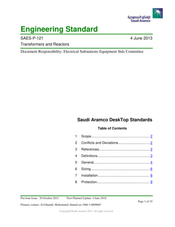
Depending on individual circumstances, it maybe desirable to change these connections or tapsbefore mounting the transformer on the pole. Forthree-phase installations, it is important that the con nections (and taps) be alike on all three phases.Care must be used in replacing the cover or hand hole cover. If the gasket is not properly in place orthe cover not securely bolted, moisture in the formof rain or snow may be driven or sucked into the tank.PARALLEL OPERATIONfor short-circuit protection--not for overload protec tion. It will be found that fuse outages will begreatly reduced if a minimum rating of 10 amperes isused. This is particularly true where the fuse isconnected ahead of the lightning arrester or "De ion" arrester so that lightning currents must passthrough the fuse to reach the arrester.MOUNTINGSingle-phase transformers rated 100 kva and less,and three-phase transformers rated 1121/z kva andless, and rated 15,000 volts and less, may bemounted on poles.Three-phase 150-kva trans formers may be pole mounted if an auxiliary supportis provided to carry the weight of the unit. Largerratings are normally designed for platform mountingonly.When pole mounting is used, there are threegenerally accepted methods. The simplest and mosteconomical, particularly for "CSP" transformerswhere no auxiliary equipment on the pole is neces sary, is to bolt the transformer directly to the pole asshown in "A", Fig. 6. No cross-arms on the pole areused unless needed for other purposes. Square headed through bolts (Sfa-inch or 3,4-inch diameterdepending on the size of the transformer) arelocated at the proper point on the pole (for standardtransformers on 12-inch, 24-inch or 36-inch centers,depending on the size of the transformer), with theheads of the bolts toward the transformer. It isrecommended that a flat washer be used betweenthe hanger lug and the pole, and a square washerand nut used on the opposite side of the pole. Thenut should be left sufficiently loose so there is aspace large enough for the transformer hanger lugbetween the flat washer and the bolt head. Thetransformer should then be lifted and the mountingslots in the hanger lugs hooked over the bolt heads.The slots are spaced slightly less than the above12, 24, or 36 inches to facilitate entering boltsinto the slots and to allow for a tolerance in boringthe bolt holes through the pole. After the nuts onthe through bolts are tightened, the bolt head onthe upper lug will engage "jump proof lips" on thelug (on standard transformers), which will preventthe transformer from jumping off the pole if it is hitby an automobile or receives a similar impact.Transformers rated 50 kva and smaller, single phase,or 45 kva and smaller, three phase, have lugscapable of the above type bolting. Adapters areavailable for single-phase, 75- and 100-kva ratingsor for three-phase, 75-, 1121/z-, and 150-kva ratings,15,000 volts and less. These adapters should beinstalled as shown in "B", Fig. 6.calPartMWhen transformers are banked in multiple anddistributed along the line on different poles, the linedrop will usually compensate for difference inimpedance. Transformers on the same pole are notusually operated in multiple except as an emergencycondition because the losses of the units will usuallyexceed the losses of a larger unit having a ratingequal to their total. If transformers are so operated,the transformer having the lowest impedance willtake more than its share of the load. Transformersare usually considered satisfactory for parallelingif their impedances are within 7.5 percent of thelarger value for two-winding transformers or 10percent for auto-transformers, providing, of course,that their ratios are the same. However, it isadvisable, where it is probable that the load may notbe properly distributed, to take current readings todetermine the exact distribution.------ualsThree-phase transformers designed for both deltaand wye operation are normally shipped connectedfor the wye voltage.com00 - lA- 1 --- . B-. 4 6 DISTRI BUTION TRANSFORMERSanINSTALLATIONtriPROTE CTIVE LINK COORDINATION( "CSP " TRANSFORMERS ONL Y)w.Elec"CSP" transformers are provided with internally mounted protective links which are intended to fusein case a fault should develop within the winding ofthe transformer. The current-time characteristics ofthese links are shown in Fig. 5. It is important, inorder to limit the outage to the single transformer,that any fuses, circuit reclosers, or circuit breakersat branch lines or substations through which thetransformer is fed, be coordinated with the protec tive links so that the link will fuse in a shorter time.A more detailed discussion of the coordination ofover-current devices is given in Westinghouse Dis tribution Transformer Technical Data Booklet No.46-403.FUSING PRACTICES( "S " TRANSFORMERS ONLY)wwTransformers without internal breakers must beprotected by external fuses which should be selected11
.comINSTALLATIONABDIRECT POLE MOUNTINGtManOF LARGE DISTRIBUTIONTRANSFORMERS USINGADAPTER PLATESualsDIRECT POLE MOUNTINGOF SMALL DISTRIBUTIONTRANSFORMERSctricalParDOUBLE CROSS-ARM MOUNTINGOF SMALL DISTRIBUTIONTRANSFORMERS USING "T"CROSS-ARM HANGERSDESINGLE CROSS-ARM MOUNTINGOF SMALL DISTRIBUTiONTRANSFORMERS USING "T"CROSS-ARM HANGERS ANDKICKERwww.ElecDOUBLE CROSS-ARM MOUNTINGOF LARGE DISTRIBUTIONTRANSFORMERS USING "C"HANGERS12FIG. 6.Pole Mountings for Distribution Transformers .
Fig. 7 shows the proper internal and externalconnections to obtain the phase relations shown bythe vector diagrams when connecting three standardsingle-phase transformers in a three-phase bank.ualsWestinghouse Instruction Book 46-100-3, avail able upon request, shows additional external circuitconnection diagrams for the more common single-,two-, three-, and six-phase connections.1. Single-phase transformers with twofully insula ted high-voltage bushin gs (ClassA for use on delta systems-see "Note "below) or three-phase transformers. Connectthe H. V. terminals to the H. V. lines.Note:These transformers if rated windingvoltage is 8660 volts or less may also be usedon three-phase, four-wire grounded neutral cir cuits, although the transformer cost may beless for Class B-1 or Class B-2 transformers.tMWhere "T-crossarm hangers" are used, the lowercrossarm may be omitted, if desired. The "T-cross arm hanger", together with a "kicker" (availablefrom the manufacturer), is then employed as shownin "E", Fig. 6. The kicker rests directly against thepole and keeps the transformer in a vertical position.A lag screw or through bolt is desirable through thebottom hole of the kicker.connect the transformer or adjust the tap changerfor the desired voltage.anWhere two crossarms are used for mounting thetransformer on a pole (nearly all three-phase in stallations of single-phase transformers and someother installations), "T-crossarm hangers" as shownin "C" Fig. 6 for the smaller units, and "Type Changers" as shown in "D" Fig. 6 for the largerunits, are available. The hangers may be fastenedto the transformers before raising from the ground.The transformer may then be lifted by means of itslifting lugs until the hooks on the hanger can bemade to hook over the upper crossarm. The lowerportion of the hanger will then rest against the lowercrossarm and hold the transformer in a verticalposition. If desired, lag screws may be insertedthrough holes in the bottom of the hanger into thelower crossarm to prevent the transformer jumpingoff the pole in case of an impact.com00 - lA 8-1 ------------ . · 4 6 DISTRIBUTION TRANSFORMERSSee Fig. 8 for transformer class designations.arZ. Single-phase transformers with onefully insula ted high-voltage bushing and oneneu tral high-voltage bushing (Class B-1 foruse on three-phase, four-wire system withgrounded neu tral). Connect the fully insulatedlPRegardless of the type of mounting used, trans formers should always be mounted vertically so thatthe terminal blocks, circuit breakers and protectivelinks are adequately immersed in oil.caBUSHING ARRANGEMENTtriHigh-voltage, single-phase and three-phase trans formers having a high-voltage rating of 5 KV andless have wall mounted high-voltage bushings.Single-phase and three-phase transformers havinga high-voltage rating from 7.2 to 15.0 KV inclusivehave cover mounted bushings.lecHIGH VOLTAGE CONNECTIONSwww.EWhen installing a transformer, the amount of pro tective apparatus required depends upon the typeof transformer. The "CSP" transformer is completelyself-protected and requires neither lightning arres ters nor fuse cutouts. The "conventional" trans former should be provided with both lightningarresters (preferably connected for "three-pointsurge protection" ) and fuse cutouts. Hot line clampsmay be advantageously used (particularly with the"CSP" transformer) for connecting the transformerto the high-voltage lines.If the transformer has multiple high-voltage ratingor has taps, refer to the diagram nameplate or theconnection diagram specified on the nameplate, andbushing to the phase line and the neutral bushingto the neutral line which may be grounded at eachpole or at the substation only. A pad is providedon the rear of the tank so that a bolt may be insertedfor convenient grounding of the H. V. neutral to thetank if desired. To use this pad, pry out the threadprotector with a sharp tool.On "CSP" transformers of this type, only one"De-ion" arrester for lightning protection is pro vided. This arrester, when shipped, is connectedto the fully insulated bushing lead as shown on thenameplate. It may be desirable, for convenienceof mounting and connecting to the supply lines, tointerchange the line and neutral outlets of thetransformer. To do so, the "De-ion" arrester maybe physically interchanged with the coordinatingstrap.3. Transformers with one fully insulatedH. V. bushing, the other end of the H. V.winding being grounded in ternally to thetank (Class B-2 for use onthree-phase,four-wire systems with grounded neu tral).In these transformers, the L. V. neutral is usuallyalso grounded to the tank externally. On "CSP"transformers, the "De-ion" arrester is mountedadjacent to the fully insulated bushing. Connect13
.comINSTALLATION-----BVECTORDIAGRAMz0f z 0A.------.B --,.---- C -- - - '"""'"'-- H2H2H2HIHIHIBCcA-- r---- B ---HI----. - c.--- - ----1 H2H2HIHIA.-----B --- t ---C ----- ---1--- N --H- - -- tH2H2H2HIHIHI03:0 (f) .w J-LL.5o(f)0:::w:EH2uals 10::: (J0a.AbaL::'1"-Jcbc ------t----- o-f' O---r- -- -J ------ ---- E00 (z0(f)0(!)I- zoozA ------ B --t-1----- C --H- --.-- H2H2H2HIHIHIA-------- B -- --f---c.--HI--- - --.H2H2H2HIHIHIA-----B ----1 ---- C ---f----.-- N --- - --.H2H2H2HIHIHIA------B ----1--C ---f---.-HIH2HIH2HIH2tMz (0:::1wane(f) -*---- ---- LA4--- ---LC --- D 0 t;j .HlParJ JJLL. to0::: (a.caA-- ----B -- --f-- --.- C .--H-- --t---.H2 1a:: (J0a.tricb00:::w::2'0::: a::1w 0f (0:::I CD::: (f)lec(f)N- ---- ----- --JK ---#---------------- ,---------------- z0t (f)0(!)H2HI zoozH2HIH2HIH20 Jw J jJ (LL.a::O (a.b0cwww14C8 .--H-- - --.A --- r---.E -r ---r -- - --- - .-- -- Y-Y AND Y-t, CONNECTIONS ARE NOTUSED WITH STANDARD D I S TR I BU T I ONTRANSFORMERS RATED 200 KVA O RLESS H AVING SUBT R A C T I VE PO LAR I T Y, SIN C E S U B T R A C T I VE PO L A RITYIS S TA ND A RD ONLY ABO V E 8660WIND I N G VO LTA G E W HEN WIND INGS A RE NO T I N SULATED FOR YCONNECTION.NFIG. 7 .-r---- -- .*NEUTRAL ISU SU A L LY NOT CONNE CTED TONEU TRAL OF POWER SOURCE AS TRANSFORMERSM I G H T BE OVERLOADE D IF SYSTEM PHA SE L O A D SARE UNBALANCED. FOR "CSP" CONNECTIONSAND ADVANTAGES SEE I .B . 46- I 0 0 - 3Three-Phase Connection o f Standard Single-Phase Transformers.
- - ' 'CLASS ACLASSFIG. 8.CLASS AB-1CLASSB-2AND 8-3Transformer Class Designations.LOW VOLTAGE CONNECTIONSfor this is shown by Fig. 10. Should an overloadcause circuit breaker a-a' in transformer A to trip,then line wires (1) and (3) would still be fed bytransformers B and C. The neutral (2) would floatin potential and voltages (1)-(2) and (2)- (3) would bedetermined only by load impedances. TransformerC, shown dotted, should therefore be omitted andtransformers A and B used in open delta.tMthis bushing directly to the phase line. The tankshould be connected to the neutral line and shouldalso be solidly grounded at the same pole.anIuals.comI .B00-- lAINSTALLATION ---------------------------------------- - - 4 6- - 1 DISTRI B UTION TRANSFOR
''CSP" Transformer with two Cover-Mounted Bushings ''S'' Conventional Transformer (167 Kva) "CSP" Transformer with two Wall Bushings 3 Phase "CSPB" Transformer