Transcription
EACVI/ASE EXPERT CONSENSUS DOCUMENTThree-dimensional Echocardiography inCongenital Heart Disease: An Expert ConsensusDocument from the European Associationof Cardiovascular Imaging and the AmericanSociety of EchocardiographyJohn Simpson, MBChB, MD, FESC, Leo Lopez, MD, FASE, Philippe Acar, MD, PhD,Mark K. Friedberg, MD, FASE, Nee S. Khoo, MBChB, H. Helen Ko, BS, ACS, RDMS, RDCS, RCCS, FASE,Jan Marek, MD, PhD, FESC, Gerald Marx, MD, FASE, Jackie S. McGhie, Folkert Meijboom, MD,David Roberson, MD, FASE, Annemien Van den Bosch, MD, PhD, Owen Miller, BMed, andGirish Shirali, MBBS, FASE, London, United Kingdom; Miami, Florida; Toulouse, France; Toronto, Ontario andEdmonton, Alberta, Canada; New York, New York; Boston, Massachusetts; Rotterdam and Utrecht, The Netherlands;Chicago, Illinois; and Kansas City, MissouriThree-dimensional echocardiography (3DE) has become important in the management of patients withcongenital heart disease (CHD), particularly with pre-surgical planning, guidance of catheter intervention, andfunctional assessment of the heart. 3DE is increasingly used in children because of good acousticwindows and the non-invasive nature of the technique. The aim of this paper is to provide a review of the optimalapplication of 3DE in CHD including technical considerations, image orientation, application to different lesions,procedural guidance, and functional assessment. (J Am Soc Echocardiogr 2017;30:1-27.)Keywords: EACVI, ASE, Recommendation, Three-dimensional echocardiography, Congenital heart diseaseFrom Evelina London Children’s Hospital, London, United Kingdom (J.S. andO.M.); Nicklaus Children’s Hospital, Miami, Florida (L.L.); Pediatric Cardiology,Toulouse, France (P.A.); Hospital for Sick Children, Toronto, Ontario, Canada(M.F.); Stollery Children’s Hospital & University of Alberta, Edmonton, Alberta,Canada (N.S.K.); Mt. Sinai Medical Center, New York, New York (H.H.K.); GreatOrmond Street Hospital for Children, London, United Kingdom (J.M.); BostonChildren’s Hospital and Harvard School of Medicine, Boston, Massachusetts(G.M.); Erasmus University Medical Center, Rotterdam, The Netherlands (J.M.,A.V.d.B.); UMCU, Utrecht, The Netherlands (F.M.); Advocate Children’sHospital, Chicago Medical School, Chicago, Illinois (D.R.); and Children’s Mercy,Kansas City, Missouri (G.S.).All authors reported no actual or potential conflicts of interest in relation to thisdocument.This article has been co-published in the European Heart Journal – CardiovascularImaging.Attention ASE Members:The ASE has gone green! Visit www.aseuniversity.org to earn free continuingmedical education credit through an online activity related to this article.Certificates are available for immediate access upon successful completionof the activity. Nonmembers will need to join the ASE to access this greatmember benefit!Reprint requests: John Simpson, Evelina London Children’s Hospital, London, UK(E-mail: john.simpson@gstt.nhs.uk).0894-7317/ 36.00Published on behalf of the European Society of Cardiology. All rights reserved.Ó The Author 2016. For permissions please email: al echocardiography (3DE) has become importantin the management of patients with congenital heart disease(CHD), particularly with pre-surgical planning, guidance of catheterintervention, and functional assessment of the heart. 3DE is increasingly used in children because of good acoustic windows andthe non-invasive nature of the technique. The aim of this paper isto provide a review of the optimal application of 3DE inCHD including technical considerations, image orientation, application to different lesions, procedural guidance, and functional assessment.THREE-DIMENSIONAL ECHOCARDIOGRAPHIC IMAGINGTECHNIQUESTransducersThe evolution of 3DE techniques and transducer technology hasbeen well described.1-3 The development of the matrix arrayprobe with parallel processing has made real-time 3DE possiblesince the 1990s.4,5 Later generations of transducers have becomesmaller with footprints similar to two-dimensional echocardiography (2DE) transducers. The development of a small highfrequency pediatric 3DE transducer (2–7 MHz) has enhancedspatial and temporal resolution, especially pertinent for small children with high heart rates.6,7 Similarly, miniaturization hasenabled the development of adult-size 3D transesophageal echocardiography (TEE) probes.81
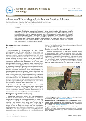
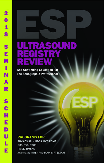
2 Simpson et alJournal of the American Society of EchocardiographyJanuary 2017Figure 1 Cross-plane imaging. (A) Cross-plane imaging of the mitral valve by transthoracic echocardiography showing the userdefined cut plane (dotted line and triangle) to show a short-axis view of the mitral valve (left panel) and the corresponding longaxis view (right panel). (B) Cross-plane imaging of mitral valve regurgitation which permits precise localization of regurgitant jets inthe long-axis (left panel) and short-axis views (right panel). The cut plane is indicated by the triangle. LA, Left atrium; LAX, longaxis; LV, left ventricle; MV, mitral valve; SAX, short axis.WorkflowIdeally, 3DE transducers should be capable of producing 2D imageswhich are at least equivalent to 2DE transducers. Some 3D transesophageal transducers achieve this, but transthoracic 3DE probes still do notgenerally match the image quality of a dedicated 2D transducer. The difference remains most marked for high-frequency pediatric 3DE probescompared with the 2DE equivalent transducer. Consequently, the useof the combined 2DE–3DE transducer is not routine in smaller patients.Manufacturer recommendations suggest that current 3D TEE probesare used for patients 30 kg. Some pediatric cardiologists will extenduse of such probes to smaller patients. Those undertaking such procedures should be aware of the specific manufacturer recommendation forthe transducer. In any patient, the risk of complications such as damageto the oropharynx and oesophagus caused by an oversized probe needsto be balanced against the additional value of 3DE. For patients who arecurrently too small to accommodate 3D TEE transducers, epicardial 3Dimaging with a transthoracic 3DE transducer is a feasible alternativetechnique during surgery.9Data Acquisition ModesGood spatial and temporal resolution in 3DE is a priority for imagingof CHD, particularly valve pathology and complex lesions. The matrix transducer has different modalities of data acquisition whoseuse is dictated by the clinical question. For example, in the assessmentof double outlet RV, the incorporation of the AV valves, ventricularseptum, and great arteries is necessary for decision-making, whereasmeasuring the size of an isolated VSD does not require such anextended field of view. The exact configuration and nomenclatureof different modes is vendor specific but with features in common.2D Simultaneous Multiplane Mode. Current matrix probesallow 360 electronic rotation of the imaging plane as well as simultaneous display of more than one 2D imaging plane that can be electronically steered in the elevation or lateral plane. The crop plane ismarked on the projection but with the drawback that temporal resolution is reduced.10 Applications include assessment of atrial septaldefect (ASD) size and rim length,11 size and shape of VSDs, AV valve
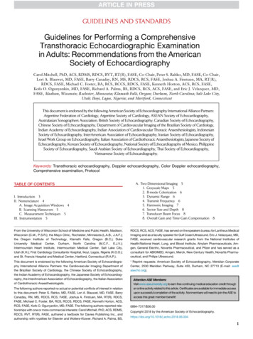
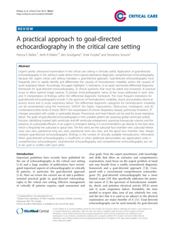
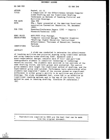
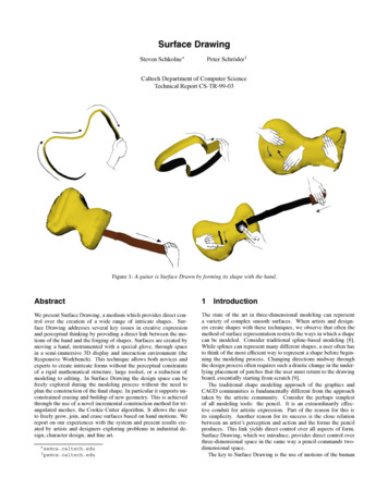
Simpson et al 3Journal of the American Society of EchocardiographyVolume 30 Number 1morphology and regurgitation (Figure 1A and B), outflow tracts andarterial valves.Real-Time 3DE Mode. Real-time 3DE permits a display of anadjustable pyramidal volume, minimizing the issue with poor cooperation in children because there is no potential for ‘stitch’ artefactsbetween adjacent subvolumes. Increasing the region of interest decreases frame rate, and the limited field of view is a disadvantagefor complex CHD where the relationship of different structures toeach other is crucial for decision-making. Some manufacturers havea further 3D mode which permits the operator to select an area of interest but with relatively low frame rates particularly if colour flowDoppler is added. This mode is mainly used during catheter intervention, particularly ASDs, VSDs, and the AV valves. Depending on thesystem, vendor settings may be adjusted to allow the operator to prioritize volume rate at the expense of line density, thus achieving ahigher temporal but lower spatial resolution.ECG-gated Multi-beat Acquisition. With current imaging technology, ECG-gated multi-beat image acquisition is frequently usedfor pediatric 3DE because it acquires a large field of view with sufficient temporal resolution. However, the electronic ‘stitching’ of narrow volumes of data over 2–6 heartbeats may produce artefactsrelated to patient breathing or movement, particularly in young children. This is not an issue in ventilated children under general anesthesia, because ventilation can be suspended briefly, and is less of aproblem during sleep or with sedation. Although ‘single-beat’ volumeacquisition has been introduced, the limited temporal resolution isinsufficient for high heart rates of infants and children unless the region of interest is small thereby permitting narrowing of the imagingsector, or if the region of interest is relatively static.3DE Color Flow Doppler. 3DE color flow Doppler can be added toany of the above modalities. In common with 2DE, the addition of colorflow Doppler reduces temporal resolution. Depending on the size ofthe region of interest, the achievable frame rate may be too low forfast moving structures such as AV valves. Some manufacturers maypermit the user to prioritize temporal resolution over spatial resolutionto maintain an acceptable frame rate. The alternative is to use an ECGgated multi-beat acquisition to maintain an acceptable frame rate.Principles of 3DE Acquisition3DE for CHD utilizes the same transducers and ultrasound systems asadults with the addition of high-frequency probes suitable for imagingbabies and children. General points are summarized below withemphasis on points relevant to the child or adult with CHD. In all patients, meticulous attention to 2D image quality is necessary to optimize the quality of the 3DE dataset. A high-frequency 3DEtransducer should be used where possible, especially in small childrenwhere ultrasound penetration is not an issue, and the sector width narrowed to include only the regions of interest. Axial resolution is higherthan either lateral or elevational planes which impacts on the optimaltransducer position for the lesion being evaluated. For example, themitral valve may be interrogated either from apical or parasternalview to delineate both leaflets and the subvalvar apparatus.12 Reviewof the multiplanar images is particularly important prior to display ofrendered images to avoid diagnostic error. Comprehensive reviewsof 3DE artefacts have been published for reference.13Imaging of relatively static cardiac structures, such as ASDs andVSDs, may be achieved using live 3DE or 3DE ‘zoom’ modesbecause temporal resolution is sufficient. Gain settings during acquisition and post-processing are particularly important in smaller patients with thin valves to reduce ‘noise’ that may impedevisualization (Figure 2A and B) while avoiding ‘holes’ or other artefacts from inadequate gain. The normal gain setting for a 3DE acquisition is slightly higher than conventional 2DE as gain can bereduced during post-processing to optimize the image, whereas iftoo little gain is used during acquisition, increasing gain duringpost-processing does not restore parts of the image which havenot been adequately visualized during the acquisition. This affectsthin structures such as valve leaflets in particular.Presentation of 3DE images of CHD merits particular consideration, especially for valves, and individualized tilt or rotation to displaythe region of interest can help (Figure 3A and B). The 3D displaymodes for CHD are analogous to those used for adults and include(i) volume rendering, (ii) surface rendering, and (iii) multiplanar reformatted (MPR) image display.14,15 Volume-rendered datasets can beelectronically segmented, allowing the operator to ‘crop’ the heartin multiple sections to expose the cardiac structure of interest fromany desired angle. This is especially useful for CHD prior to surgeryor intervention. Surface rendering presents the surfaces of structuresor organs with a solid appearance and is mainly used to visualize size,shape, and function of cardiac structures.16 Analysis software for thismode includes semi and fully automated endocardial border detection for quantification of left ventricular (LV) and RV function17,18as well as semi-automated mitral leaflet motion detection for quantification of valve function, both of which may be limited by theabnormal ventricular shape or valve morphology found in CHD.MPR allows the 3DE dataset to be viewed on a quad screen with the3D dataset cut into three planes (sagittal, coronal, and transverse)which are configurable by the user. Adjustment of the MPR planes isillustrated in Supplementary data online, Powerpoint 1. This displayof planes not available by 2DE can aid with understanding complexanatomies and facilitate measurement of many CHDs such as ASDand VSD size. Valve areas, effective orifice areas, and vena contractaareas of regurgitant jets can all be measured by manipulating cuttingplanes to avoid foreshortening or oblique measurements.19-21Future DirectionsImproved temporal resolution of single-beat acquisitions or postprocessing software to deal with stitch artefacts would enhance3DE in younger patients. Software packages that can accommodateanalysis of valves and chambers of abnormal morphology wouldalso benefit the patient with CHD.RecommendationsThe 3DE approach should be tailored according to the patient. Smallfootprint and high-frequency 3DE transducers should be used in infants and young children and for epicardial 3DE.3D TEE should be considered when patient size permits if 3D TTEprovides insufficient imaging to plan therapy.IMAGE DISPLAY AND ORIENTATIONPublished standards have been produced for the echocardiographicassessment of patients with pediatric and CHD, including TTE,22TEE,23 and quantification.24 Recent published work has definedstandards for adult practice using 3DE,14 but the latter specifically
4 Simpson et alFigure 2 Effect of gain setting on 3D images. (A) Transthoracicparasternal long axis view of the LV with inappropriately highgain settings. The cavity of the left atrium and left ventricle is opaque and consequently there is no perception of depth in the image.(B) With appropriate reduction of gain, intracavity noise has beenremoved and far-field structures can be visualized. In this example,far-field structures are colour coded blue grey and near fieldbrighter and yellow-brown. LA, Left atrium; LV, left ventricle.excluded CHD. In the patient with CHD, cardiac position, situs,connections, and alignments may be abnormal which presents a major challenge compared with acquired heart disease. 3DE facilitatesen face projections of cardiac septums and AV valves,25 which can berotated in the z-plane to any desired orientation. If the analogy of aclock face is used, the use of z-plane rotation turns the image in aclockwise or counter clockwise direction to achieve an anatomicallycorrect orientation (see Supplementary data online, Presentation 1).The retention of adjacent anatomic landmarks is desirable, wherepossible, to assist orientation. Echocardiographic evaluation of thepatient with CHD is often complemented by other imaging modalities including magnetic resonance imaging (MRI), computed tomography (CT), and angiography. To gain maximum value, theorientation of 3DE images should be both consistent and intuitive,as exemplified by the ‘anatomic’ approach to image display,26 projecting the heart in the same orientation as a person standing in anJournal of the American Society of EchocardiographyJanuary 2017Figure 3 Rendered views of the mitral valve by transthoracic3DE. (A) This is a projection of a normal mitral valve viewedfrom the ventricular aspect. The mitral valve is viewed directlyen face so that the leading edge of the anterior and posteriorleaflets can be visualized along with the aorta in the far-field.(B) This is a similar projection of the mitral valve to thatshown in (A). However, the rendered image has been rotatedslightly so that the depth of the anterior leaflet of the mitralvalve can be visualized. This assists in imaging of abnormalities in this region such as true clefts of the mitral valve orthe bridging leaflets in atrioventricular septal defects. AMVL,Anterior mitral valve leaflet; Ao, aorta; PMVL, posterior mitralvalve leaflet.upright position. With this approach, superiorly positioned structures will be displayed uppermost on the image. This anatomicallycorrect approach is consistent with the projection of MRI and CTimages.26,27 The application of an anatomic orientation can beillustrated with specific examples.The Atrial SeptumThe atrial septum can be visualized from the right or left atrial aspect.A projection from the right atrium permits visualization of important
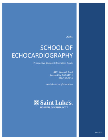
Journal of the American Society of EchocardiographyVolume 30 Number 1Simpson et al 5Figure 4 Normal atrial septum. Transesophageal 3DE view of thenormal atrial septum viewed from the right atrial aspect. The orientation of the image is anatomic so the superior vena cava and inferior vena cava are shown uppermost and lowermost on the imagerespectively. This image was acquired by 3D TEE using a fullvolume acquisition over four cardiac cycles. The asterisk marksthe margins of the oval fossa. CS, Coronary sinus; IVC, inferiorvena cava; SVC, superior vena cava; TV, tricuspid valve.landmarks such as the superior vena cava, inferior vena cava,ascending aorta, tricuspid valve, oval fossa, and os of the coronary sinus. The preferred anatomic image orientation has the superior venacava uppermost and tricuspid valve seen to the right of the atrialseptum (Figure 4).The Ventricular SeptumThe ventricular septum can be visualized from either the RVor the LVaspect. By convention, the components of the ventricular septum arenamed as if the septum is viewed from the RV side with the free wallof the RV removed. With the anatomic approach, the diaphragmaticborder of the heart is lowermost, the RV apex is seen to the right andthe RV outflow tract viewed uppermost on the projected image sothat landmarks such as the tricuspid valve, moderator band, and septomarginal trabeculation are seen in anatomically appropriate position (Figure 5A). Similarly, the LV aspect of the ventricular septumcan be viewed in an anatomic projection (Figure 5B), to includeboth the septum and LV outflow tract.AV ValvesIn CHD, the left-sided AV valve may not be a bileaflet valve of ‘mitral’type and the right-sided AV valve may not be the tricuspid valve.Regardless of the morphology of the valve, or whether an en faceview is projected from the ventricular or atrial aspect, the 3D renderedimage is rotated so that the diaphragmatic surface of the heart is shownlowermost (Figure 6A and B). This means, for example, that the superior bridging leaflet in an AV septal defect will be shown uppermost onthe image and the inferior bridging leaflet lowermost (Figure 7).Aortic and Pulmonary ValvesThe morphology, position and patency of the aortic, and pulmonaryvalves cannot be assumed in CHD. These valves are therefore projected in an anatomic format using the standard conventions fornomenclature of the valve leaflets. For example, the aortic valve maybe projected as if seen from the ascending aorta or from the LVoutflowFigure 5 (A) Transthoracic rendered 3DE image of the right ventricular side of the normal ventricular septum. The free wall ofthe right ventricle has been cropped away in post-processing.The important landmarks can be readily identified including thetricuspid valve, ventriculo-infundibular fold, and septomarginaltrabeculation (septal band). This type of view can be used to project all types of ventricular septal defects. (B) Left side of thenormal ventricular septum. A full-volume 3DE dataset was obtained by transthoracic 3DE in a paraseternal long-axis view.The free wall of the left ventricle has been cropped away sothat the ventricular septum can be directly visualized from theLV cavity. The smooth wall of the left ventricle can be appreciated. Ao, Aorta; LA, left atrium; LV, left ventricle; RA, right atrium;TV, tricuspid valve; VIF, ventriculo-infundibular fold.tract. The conventional nomenclature of left, right, and noncoronaryleaflets and sinuses is used in exactly the same fashion as in 2DE. Anexample of the preferred orientation of the aortic valve is shown(Figure 8) and a similar approach is used for the pulmonary valve.Complex Abnormalities of Cardiac ConnectionsWhen the main cardiac connections are abnormal, an anatomicpresentation of images is particularly important so that theabnormal anatomy is displayed in a manner as close as possible
6 Simpson et alJournal of the American Society of EchocardiographyJanuary 2017Figure 7 Transthoracic 3DE en face view of atrioventricularseptal defect. En face view of a complete atrioventricular septaldefect from the ventricular aspect, obtained using a subcostalview. The depth of field means that the superior bridging leafletand the common atrioventricular valve are seen as well as theaorta in the far field. Ao, Aorta; AVV, atrioventricular valve;SBL, superior bridging leaflet.Figure 6 (A) Transesophageal 3DE view of the mitral valve fromthe atrial side. The mitral valve, aortic valve, and left atrialappendage are visualized from the atrial aspect in an anatomicorientation. If the annulus of the mitral valve is viewed as a clockface, the aortic valve is at 2 o’clock with reference to the mitralvalve. (B) Transesophageal 3DE view of the mitral and tricuspidvalves from the ventricular side. The mitral and tricuspid valvesare viewed from the ventricular aspect in an anatomic orientation.The aorta is at a 10 o’clock position with reference to the mitralvalve. The inferior, septal, and anterosuperior leaflets of thetricuspid valve are seen in anatomic orientation as well as thecurved shape of the ventricular septum. AMVL, Anterior mitralvalve leaflet; Ao, aorta; ASL, anterosuperior leaflet of the tricuspidvalve; IL, inferior leaflet of the tricuspid valve; LAA, left atrialappendage; MV, mitral valve; PA, pulmonary artery; PMVL, posterior mitral valve leaflet; SL, septal leaflet of the tricuspid valve.to the actual spatial locations. An accurate understanding of therelationship of intracardiac structures has a direct impact on the surgical approach.‘Surgical’ Views of the HeartThe term ‘surgical’ view has been used to describe 3D projections thatare most akin to the surgeon’s view during an operation. There arespecific considerations for this term, particularly in contrast to the‘anatomic’ view. The anatomic view is projected as if the person isstanding upright, whereas a surgical view is projected as if the patientis lying supine with the lead surgeon operating from the right side ofFigure 8 En face view of the normal aortic valve. Transesophageal 3DE view of a normal aortic valve viewed from the aorticside of the valve. L, Left coronary leaflet; LA, left atrium; N, noncoronary leaflet; PV, pulmonary valve; R, right coronary leaflet;RA, right atrium.the patient. The effect of this is that an anatomic en face view of theright side of the atrial or ventricular septum would be rotated counterclockwise 90 when projecting a ‘surgical’ view (Figure 9). Views ofthe atrial aspect of the AV valves are often referred to as ‘surgical’even though the surgeon may take a different access route to repairthe valve in question. For example, the truly surgical view of the mitralvalve would be presented with the patient supine with the left atriumaccessed through the atrial septum. This contrasts with the usual projected 3DE view obtained by cropping away the posterior aspect ofthe atriums and rotating the AV valves en face with rotation of thewhole dataset into an anatomic position. In practice, our preferenceis an anatomic orientation, which maintains consistency with projections of MRI and CT scans, knowing that ‘surgical’ visualization of thestructures may be different. A visual demonstration of the commonmanipulations of 3D datasets accompanies this document (seeSupplementary data online, Presentation 1).
Simpson et al 7Journal of the American Society of EchocardiographyVolume 30 Number 1En face views of septums and AV valves should retain importantlandmarks and be rotated into a correct anatomic orientation.The term ‘surgical’ view should be used only for projections thatshow anatomy as the surgeon would visualize the region of interest.OPTIMAL SONOGRAPHIC PROJECTIONS FOR DIFFERENTCONGENITAL HEART LESIONSStandard imaging planes in 2DE have been developed from a combination of anatomical constraints and accessible sonographic windows, forming the basis for published standards.22 3DE is lessconstrained since post-processing will allow interrogation of structures contained within the acquired volume. A corollary is that astructure of interest can be displayed similarly after postprocessing despite being acquired from a range of different echocardiographic windows. However, the principles of imaging physicsapply as much to 3DE as they do to 2DE. For this reason, thereare optimal approaches for data acquisition that should allow foroptimal demonstration of the structure of interest. General recommendations can be made about the optimal acoustic windows toshow different regions of interest. These include the following:(i) clear visualization of the region of interest on 2DE(ii) insonation orthogonal to the plane of the structure of interest wherepossible(iii) inclusion of clinically relevant adjacent structures(iv) optimization of volume width and depthFigure 9 3D TEE views of ‘surgical’ vs. anatomic views of anatrial septal defect. (A) Atrial septal defect viewed from the rightatrial aspect in an anatomic orientation with the superior venacava uppermost and inferior vena cava lowermost on the image.(B) Atrial septal defect viewed from the right atrial aspect in a‘surgical’ orientation where the defect is viewed from the rightside in an analogous fashion to the patient in a supine position.This amounts to a 90 counterclockwise rotation of the anatomicprojection. CS, Coronary sinus; IVC, inferior vena cava; SVC, superior vena cava.Future DirectionsThe availability of orientation markers, already available for CT angiography and MRI, is needed for 3DE to mark, for example, the true left/right or superior/inferior orientation of an image. This should be coupledwith the ability to ‘landmark’ important anatomical structures to enhancedisplay of complex CHD as the data is manipulated. Fusion imaging,where 3DE datasets can be co-registered with datasets from other modalities (fluoroscopy, CTangiography, and MRI), will allow for both automated anatomic orientation of 3DE images and visualization of regionswhich may be sonographically inaccessible. Widespread implementationwould require co-registration across vendors, modalities, and platforms.RecommendationsAn ‘anatomic’ approach to image display is recommended as it reflects the real position of structures in space and is consistent withother modalities such as MRI and CT.For example, acquiring a 3D dataset to display an ASD is bestachieved in a subcostal window because insonation from this viewis orthogonal to the plane of the atrial septum. With TEE there isless flexibility to adjust the sonographic window; however, this isoffset by higher image quality than TTE.28Although image quality is central to interrogation of regions of interest and good 3D reconstruction, there are important differencesfrom 2DE. For example, parasternal long-axis (PLAX) and parasternalshort-axis (PSAX) views are used in 2DE to evaluate a perimembranous VSD (pmVSD) because the defect is in the near field, andgood alignment to Doppler jets can be achieved. However, 3DE isespecially useful for its ability to display VSDs en face and to delineateadjacent structures. PLAX and PSAX views are limited because of thesmall size of the ultrasound sector in the near field. Thus, subcostaland modified apical views may better define adjacent structuresbecause the VSD is in the centre of the imaging field with a widersector. This tailored approach is also employed for more complex lesions such as double outlet RV where AV valves, ventricular septum,and outlets all have to be incorporated into the 3DE volume.29Table 1 summarizes optimal TTE sonographic views and the usefulness of 3D TEE for common forms of CHD.Technical limitations may, however, persist irrespective of the imaging plane. Both the aortic and pulmonary valves are thin, rapidlymoving structures. These are often imaged by 3D TTE using aPLAX or PSAX view where the plane of insonation does not lend itself to good quality rendering of the entirety of individual valve leaflets, particularly the body of the leaflet. This issue can be overcome byTEE in patients large enough to accommodate the 3D TEE probe.RecommendationsOptimal Sonographic Projections for Different CongenitalHeart Lesions. The angle of insonation should be tailored to the
8 Simpson et alJournal of the American Society of EchocardiographyJanuary 2017Table 1 Suggested transthoracic acoustic windows and utility of 3DE for CHDSubcostalApicalPLAXPSAX3D-TEEASD (modified) (modified) (modified) SV ASD Atrial septum AV junctionAVSD (LAVV) (LAVV)Ebstein’s/TV dysplasia (Anterior angulation) (smaller patients) MV chordal structureDouble orifice MV MVPParachute MV Supra mitral membrane Ventricular septummVSD (except anterior defects
Three-dimensional echocardiography (3DE) has become important in the management of patients with . to provide a review of the optimal application of 3DE in CHD including technical considerations, image orientation, applica-tion to different