Transcription
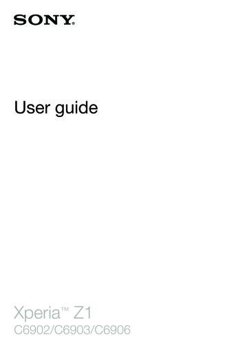
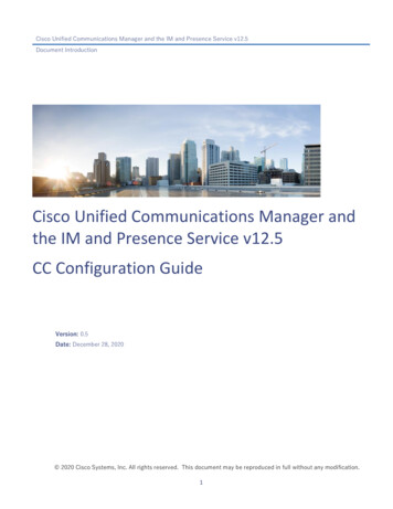
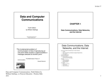
CDMA and GSM1Mobile communications: IS-95 and GSM1.IntroductionTwo second generation cellular systems are currently being deployed the Global System for Mobile Communications (GSM) and the Code DivisionMultiple Access (CDMA) systems. These occupy frequency bands near 900 and1900 MHz (at the higher band, they are known commercially as PCS). GSM iscurrently the most popular cellular system world wide, with 50% of the market;CDMA is a newer standard, with a higher capacity, and widely used in NorthAmerica.The third generation of mobile systems, IMT-2000 (International MobileTelecommunications at 2000Mhz)[1], is currently being developed and willintegrate different methods and environments (cellular, cordless, satellite, Lan’s).It will offer a wide range of telecommunications services including voice, data,multimedia and Internet. Initial data rates will be up to 2Mbps. IMT-2000 shallprovide global seamless roaming and services and increased security andperformance. The principle objective of IMT-2000 is to provide an internationalstandard to support a wide range of radio and service environments with globalroaming (see Figure 1).Figure 1P. Kropf
CDMA and GSM2.2IS-95 Cellular SystemThe IS-95 standard describes a Code Division Multiple Access (CDMA)system in which the audio band data signal is multiplied by a high rate spreadingsignal. This spreading signal is formed from a pseudo-noise code sequence,which is then multiplied by a Walsh code for maximum orthogonality to (ie. tohave low cross-correlation with) the other codes in use in that cell. Typically,CDMA pseudo-noise sequences are very long, thereby giving excellent crosscorrelation characteristics. (IS-95 uses a 242-1 chip period, derived from a 42 bitmask.)The IS-95 system can be thought of as having many layers of protectionagainst interference. It allows many users to co-exist, with minimal mutualinterference. They can be described by the signal conditioning sequence thatoccurs on forward and reverse channels (Figure 1 and Figure 2, respectively).The forward channel carries information from the base station to the mobile unit;the reverse channel carries information from the mobile unit to the basestation[2]. The transmission channels are shown; the reception of each channelfollows the reverse sequence.The forward channels are between 869 and 894 MHz, while the reversechannels are between 824 and 849 Mhz. Within these bands, four sub-bandsare available for CDMA, of widths 1, 0.1, 9 and 10 MHz; in the U.S., 1.25 MHzsub-bands near 849 and 894 MHz are employed. All cells in the same area canemploy the same spectral band, because the various signals are sorted out bythe spread spectrum process rather than by frequency discrimination.P. Kropf
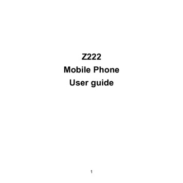
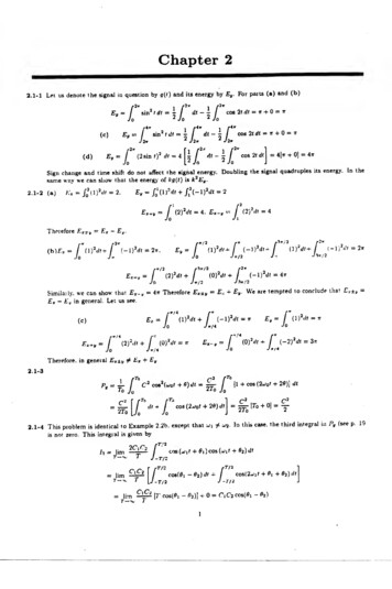
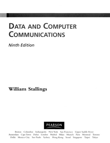
CDMA and GSM3Power Control Bit9.6, 4.8, 2.4, 1.2 kbpsConvolutionEncoder19.2 kbpsDataRepeaterData Scrambling19.2 kbpsBlockInterleaverMultiplexer4 bitsLong CodeGeneratorDecimator 6419.2 kbpsPower bitlocator1.2288 Mbpscos ωctI Pilot Sequence1.2288MHz19.2 alsh CodeGeneratorQ Pilot Sequence-sin ωctFigure 1: Forward CDMA ChannelForward channel transmission sequence:1. Convolution encoder2. Repetition circuit3. Block InterleaverEncodes the data from one stream to two,doubling the nominal rate from 9.6 kpbs to 19.2kbps, 4.8 kbps data to 9.6 kbps, etc.Repeats coded symbols, so lower rate encodeddata is increased from 9.6, 4.8 or 2.4 kbps to19.2 kbps.Reads data into the rows of a 24 x 16 array, andout of the columns; introduces a 20 msec delay,but spreads important bits (as produced bymodern speech encoders) over time as proofagainst deep fades or noise bursts.P. Kropf
CDMA and GSM4. Data scrambling5. Power control6. Orthogonal covering7. Quadrature spreading8. Quadrature modulation9. RF modulation4thThe data are Modulo 2 added to every 64 bit ofa pseudo-noise (PN) sequence created from a4242 bit shift register. (The resulting 2 -1 bitsrepeat once per century after initiation.) Thedata rate at this point is still 19.2 kbps.Every 1.25 msec, or 24 data symbols, a powercontrol bit is inserted, in order to instruct themobile unit to raise or lower its power (toequalize the power received from every mobileunit in the cell.) The location of the powercontrol bit is determined from the PN sequence.The 19.2 kbps data are spread with a 1.2288Mbps Walsh function, so that each one bit datasymbol is spread by 64 Walsh chips. The Walshfunction provides 64 mutually orthogonal binarysequences, each of length 64.The data are split into two bit streams, which areModulo 2 added to two different but well defined“Pilot” pseudo-noise sequences generated from15 bit shift registers. The code repeats 75 timesevery 2 seconds, or at 26.7 msec intervals.The binary I and Q outputs are mapped ontofour phases of a quadrature modulator, at π/4and 3π/4, using quadrature phase shift keying(QPSK).The baseband quadrature data are raised to theforward cellular radio band, 869 to 894 MHz.The IS-95 channel occupies 1.25 MHz withinthis band, the rest of which is occupied by othercellular services such as AMPS.Of the 64 available orthogonal channels (ie. channels which haveminimum mutual interference), one is assigned to the pilot channel and one tothe synchronization channel. Several low numbered channels are assigned topaging.The pilot channel corresponds to the all zeros Walsh code (Walshchannel 0), and contains the unmodulated quadrature PN spreading code. It istransmitted at higher power than the user channels, and is provided so that eachsubscriber within the cell can determine and react to the channel characteristicswhile employing coherent detection.Walsh channel 32 is assigned to the sync channel, which provides timeand frame synchronization to the mobile unit. Time of day and stationidentification are continuously broadcast on this channel.As users are added to the system, they are assigned user channels fromthe available Walsh channels. When over 60 users are present, the channelsP. Kropf
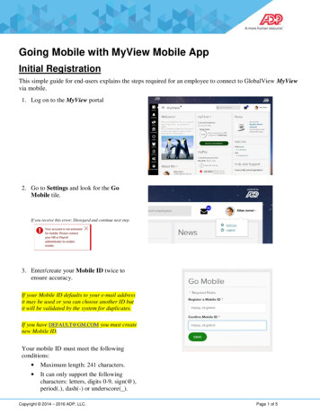
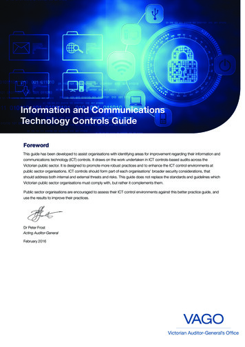
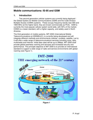
CDMA and GSM5are assigned to multiple users, and protection from mutual interference within thesame Walsh channel is provided by the private PN sequences that encode eachuser link. The number of users can therefore rise to large values, whilereasonable quality is maintained.SpeechDecoder28.8 Walsh CodeGeneratorOrthogonalMapper307.2 kbpscos ωctI Pilot SequenceI(t)BasebandFilter1.2288MHzData BurstRandomizerHalfChipDelayBasebandFilterLong CodeGeneratorQ(t)-sin ωctQ Pilot SequenceFigure 3: Reverse CDMA ChannelReverse channel transmission sequence:1. Speech encoderProduces nominal 9600 bps data stream,dynamically reduced to 4800, 2400, or 1200 bpsduring pauses and gaps in speech; quiet periodscorrespond to 1200 bps data.P. Kropf
CDMA and GSM62. Convolution encoderEncodes the data from one stream to three,tripling the data rate from 9.6 kpbs to 28.8 kbps,4.8 kbps data to 14.4 kbps, etc.3. Repetition circuitRepeats coded symbols, so lower rate encodeddata is increased from 9.6, 4.8 or 2.4 kbps to19.2 kbps.4. Block InterleaverReads data into the columns of a 32 x 18 array,and out of the rows; introduces a 20 msec delay,but spreads important bits over time as proofagainst deep fades or noise bursts.5. Orthogonal mappingThe 28.8 kbps data are split into sequential setsof six bits each, which are mapped to one of 64Walsh functions. The data rate is thereforeraised to 28.8 k x 64 chips/ 6 bits 307.2 kpbs.6. Burst RandomizingThe Walsh symbols are broken into groups ofsix, each group being 1.25 msec in duration.These are collected into frames of 16 powergroups, or 1.25 msec x 16 20 msec. At 9600bps, all 16 groups are transmitted; at 4800 bps,8 randomly selected groups are transmitted; at2400 bps, 4 groups; at 1200 bps, 2 groups. Thetransmitted groups are chosen randomly,according to a formula based on 14 bits of thePN sequence of the second last group in theprevious frame.7. Direct sequence spreadingThe data are Modulo 2 added to every bit of apseudo-noise (PN) sequence created from a 42bit shift register. The PN sequence is generatedat 1.2288 MHz, so each Walsh chip is spread byfour long code PN chips.8. Quadrature spreadingThe data are split into two bit streams, which areModulo 2 added to two different but well defined“Pilot” pseudo-noise sequences generated from15 bit shift registers.9. Quadrature modulationThe binary I and Q outputs are mapped ontofour phases of a quadrature modulator, at π/4and 3π/4, using offset quadrature phase shiftkeying (OQPSK). (The Q channel is shifted byhalf a chip for improved spectral shaping.)10. RF modulationThe baseband quadrature data are raised to thereverse cellular radio band, 824 to 849 MHz.The IS-95 channel occupies 1.25 MHz withinthis band, the rest of which is occupied by othercellular services such as AMPS.P. Kropf
CDMA and GSM7Note that there is continuous transmission from a cell phone when aconversation is in progress. The lowest data rate is 1200 bps, with three 1.25msec “power control” groups being transmitted in every 20 msec frame. Amobile phone is therefore not silent during conversations, and can be located byits telltale emissions.Spectral ConsiderationsA generic spread spectrum occupies most of the available 1.25 MHzbandwidth. The spectral shape is best described by a sinx/x function, with manyvariations, such as pulse shaping, to curb out of band components. The CDMAspectrum is nearly flat-topped, and does not have the prominent sidelobes(Figure 5).The final spectral shape of the CDMA forward link spectrum is given by theQPSK (quadrature phase shift keying) modulation process. The I and Q Pilotcodes, at 1.2288 MHz, modulate the I and Q channels independently, and theQPSK process spreads out the spectral peaks left by the Walsh code.CDMAsignalSpreadSpectrumSignalfcRF FrequencyFigure 5: Spectral Shape of a generic Spread Spectrum signal [3] and aCDMA signalThe 1.2288 MHz Walsh code modulates the 19.2 kbps data to produce an“orthogonal covering”. While separate Walsh codes have low cross-correlation,the Walsh code has a characteristic spectral signature (Figure 6).P. Kropf
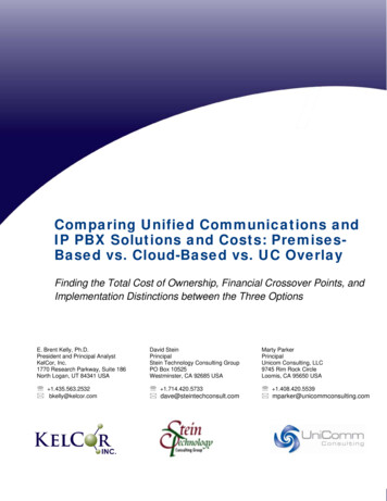
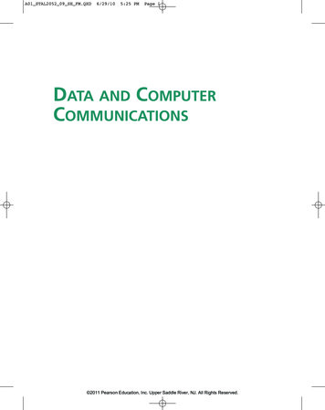
CDMA and GSM8fcRF FrequencyFigure 6: Spectral Shape of a Walsh coded signal.3.Global System for Mobile Communications (GSM)The most popular second generation system installed worldwide is theGSM, Global System for Mobile Comunications. The GSM system is based on125 frequency allocations and eight timeslots per channel, giving a total of 1000Channels. These may be message-carrying traffic channels, or controlchannels.The frequency allocations (ARFCN, or absolute radio frequency channelnumber), are each 200 kHz in bandwidth. The forward ARFCNs are between935 and 960 MHz; the reverse ARFCNs are between 890 and 915 MHz, so thata given mobile unit receives at a frequency exactly 45 MHz greater than the onethat it transmits.Since 1995, new bands have opened up at 1800 and 1900 GHz. Knownas PCS (Personal Communication Services), vendors have been free to choosefrom a variety of standards. IS-95 is the standard used for CDMA applications,with some modification for higher rate data, while the GSM standard has alsobeen moved up to the higher bands, under the names DCS 1800 and DCS 1900(for 1800 and 1900 MHz, respectively). The principles described here also applyfor the upper bands.If there are multipath problems in a cell, then the cell is designated as a“hopping cell”. Hops occur on a frame by frame basis, up to 217.6 hops persecond, over a selection of 64 hop carrier frequencies.The timeslots (TS) are each 576.96 microseconds (µsec) in duration.Eight timeslots make a frame, 26 frames make a multiframe. Because GSM isessentially a time division multiple access (TDMA) system, rather than a spreadspectrum system, the time frame structure is shown in Figure 4. With guardtimes of 8.25 µsec on the end of a timeslot, a timeslot carries 148 usable bits ofinformation; 114 of these are the message payload, the remainder are 26 bits ofmidamble for frame synchronization, 6 start/stop bits, and 2 “stealing bits” forinserting priority control messages.P. Kropf
CDMA and GSM9Control channels are TS0 on 34 designated carrier frequencies(ARFCN’s); that is, of 1000 physical channels, 34 are set aside for paging andbroadcast, frequency correction, and timing synchronization. Some are for thehandshaking process to initiate calls - paging, acknowledgement, and grantingaccess to a regular traffic channel. Several are holding channels, to maintain aconnection while the setup process is underway.Traffic channels are of various rates, according to the need. They supportdata at 9.6, 4.8 and 2.4 kbps, and speech at 6.5 and 13 kbps.3½ hoursHyperframe2048 superframes6.12 secondsSuperframe51 multiframes120 millisecondsMultiframe01.26 frames4.615 milliseconds0Frame12345678 timeslots576.92 microsecondsTimeslot357DataTail bits126157MidambleDataSteal bitStreal bit38.25156.25 bitsguard bitsTail bitsFigure 4: GSM Frame StructureLike IS-95, the GSM system has many layers of protection againstinterference. They can be described by the signal conditioning sequence thatoccurs from speech to transmission. Unlike IS-95, forward and reverse channelshandle data in an identical manner; dissimilarities occur only in the transmissionand handling of control messages. (Figure 1 and Figure 2, respectively). Theforward channel carries information from the base station to the mobile unit; thereverse channel carries information from the mobile unit to the base station [2].The transmission channels are shown; the reception of each channel follows thereverse sequence. A speech channel is shown; control and data channels areencoded in different ways in Steps 1 to 5; thereafter, the procedure is similar.GSM speech signal conditioning sequence:1. Speech encoderProduces nominal 13 kbps data stream, with260 bits for each 20 msec of speech.2. Bit prioritizorOf 20 msec of speech, the most important 50bits are Type
Multiple Access (CDMA) systems. These occupy frequency bands near 900 and 1900 MHz (at the higher band, they are known commercially as PCS). GSM is currently the most popular cellular system world wide, with 50% of the market; CDMA is a newer standard, with a higher capacity, and widely used in North America.File Size: 254KBPage Count: 10