Transcription
COMPLEX PIPING DESIGN GUIDEFOR SELF-REGULATING HEATING CABLETHERMONINDUSTRIAL PROCESS HEATINGSOLUTIONS
Complex Piping Design GuideFor Self-Regulating Heating CableTable of ContentsIntroduction. 3Computer Aided Design Program. 3HEAT TRACING DESIGN OUTLINE. 4BASIS FOR A GOOD DESIGN.4-14Step 1: Establish Design Parameters. 4Step 2: Determine Heat Losses. 5-6Step 3: Select the Proper Thermon Heating Cable. 7-12Step 4: Determine Heat Tracing Circuit Lengths. 13Step 5: Choose Options/Accessories. 14Design Tips. 15Design Worksheet.16-17General Specification.18-19This Design Guide displays information in English and metric values wherever possible. Certain tableshave been displayed in English values only due to space constraints. Contact Thermon to obtain thesetables in metric values.2
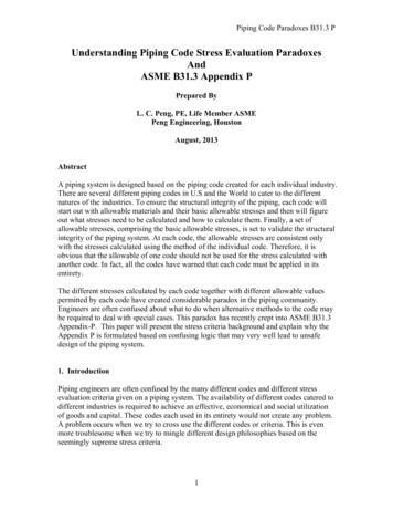
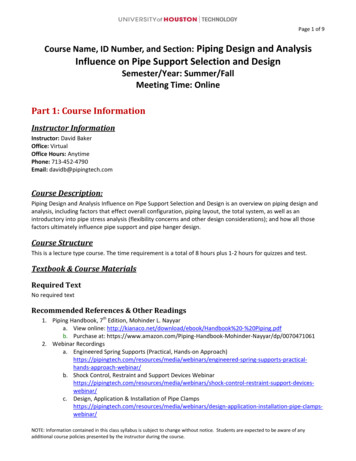
INTRODUCTIONThis design guide addresses the heat tracing requirements ofcomplex piping. Whether the application is a small project ora complete network of piping and equipment, designing anelectric heat tracing system for complex piping is simplified byusing Thermon self-regulating cables. The information containedin this design guide will take the reader through a step-by-stepprocedure to make proper heating cable selections based on: Pipe size Thermal insulation type andthickness Desired maintenance temp. Maximum exposure temp. Minimum ambient temp. Heating cable start-up temp. Available power supply Electrical area classificationAfter following the prescribed steps in this design guide, thereader will be able to design, select and/or specify or establisha bill of materials for a heat tracing system.Typically, complex piping is located inside a process unit andconsists of relatively short runs of pipe with frequent tees, as wellas in-line valves, pumps and related process equipment that alsorequires heat tracing. Circuit lengths can range from several feet(less than one meter) to several hundred feet (meters) in length;however, the average is usually 100 feet (30 meters) or less.For applications ranging from freeze protecting water linesto maintaining elevated process temperatures as high as302 F (150 C), Thermon self-regulating, cut-to-length, parallelresistance heating cables are recommended. Variations in theheat loss of the insulated pipe (due to equipment, supportsand/or insulation) are compensated for by the heating cable’sPTC (Positive Temperature Coefficient) characteristic. Thermonoffers heating cables specifically designed, manufactured andapproved to cover a wide range of applications.BSX Designed for freeze protection and temperaturemaintenance at or below 150 F (65 C), BSX is well-suited for bothmetallic and nonmetallic piping and equipment.543121. Nickel-Plated Copper Bus Wires2. Radiation Cross-Linked SemiconductiveHeating Matrix3. Polyolefin Dielectric Insulation4. Tinned Copper Braid5. Polyolefin or Fluoropolymer OverjacketRSX 15-2 Designed for applications where the watt densityrequirements preclude the use of the standard range of BSXcables.543121. Nickel-Plated Copper Bus Wires2. Radiation Cross-Linked SemiconductiveHeating Matrix3. Polyolefin Dielectric Insulation4. Tinned Copper Braid5. Polyolefin or Fluoropolymer OverjacketHTSX Designed for process temperature maintenance or freezeprotection applications up to 302 F (150 C) and intermittentexposure temperatures (power-on or off) of 482 F (250 C), andcontinuous exposure (power-off) to 400 F (204 C). The cable iscapable of withstanding the exposure temperatures associatedwith steam purging.341. Nickel-Plated Copper Bus Wires2. Semiconductive Heating Matrix andFluoropolymer Dielectric Insulation3. Nickel-Plated Copper Braid4. Fluoropolymer Overjacket12VSX-HT Designed for process temperature maintenanceor freeze protection applications up to 392 F (200 C) andintermittent exposure temperatures up to 482 F (250 C).34121. Nickel-Plated Copper Bus Wires2. Semiconductive Heating Matrix andFluoropolymer Dielectric Insulation3. Nickel-Plated Copper Braid4. High Temperature FluoropolymerOverjacketUSX Designed for process temperature maintenance andfreeze protection applications up to 464 F (240 C). Withstandsintermittent exposure temperatures (power-on or off) of 482 F(250 C), and continuous exposure temperatures (power-off) to464 F (240 C).43211. Nickel-Plated Copper Bus Wires2. Semiconductive Heating Matrix andFluoropolymer Dielectric Insulation3. Nickel-Plated Copper Braid4. Fluoropolymer OverjacketCOMPUTER AIDED DESIGN PROGRAMThermon has developed a sophisticated yet easy-to-usecomputer program, CompuTrace , that provides detailed designand performance information. Users of CompuTrace are ableto input application-specific information into the program andobtain detailed electrical and thermal performance information.Calculations made within the program are based on the formulasprescribed in IEEE Standard 515.The information input to and/or generated from CompuTracecan be printed and summary reports, including “load chart”information, exported for use in other programs. WhileCompuTrace is a valuable asset to use in designing a heat tracingsystem, the design steps detailed in this guide will still form thebasis for identifying the design process necessary to establish aproperly functioning heat tracing system.3
Complex Piping Design GuideFor Self-Regulating Heating CableHEAT TRACING DESIGN OUTLINEThe five steps below outline the design and selection processfor an electric heat tracing system. The step-by-step proceduresthat follow the outline will provide the reader with the detailedinformation required to design, select and/or specify a fullyfunctional electrical heat tracing system.Step 1: Establish Design ParametersCollect relevant project data:a. Piping/equipment Diameter — Length — Material 1b. Temperature Low ambient — Start-up temperature Maintain temperature High temperature — Limits/excursionsc. Insulation Type — Thickness — Same Size/Oversized?d. Electrical Operating voltage — Circuit breaker capacity Electrical area classificationStep 2: Determine Heat LossesUsing information gathered in Step 1 andbased on:a. Heat loss charts/tablesb. Computer design programs — CompuTraceStep 3: Select the Proper Thermon Heating CableBased on:a. Application requirements Maintain temperature Maximum exposure temperatureb. Watt density requirements Power output at maintain temperaturec. Electrical design Available voltage Circuit breaker capacity Cold start impactd. Approval requirements Hazardous area approval — CoderequirementsStep 4: Determine Heat Tracing Circuit LengthsBased on cable selection, electrical design andpipe lengths with allowances for; Valves, pumps, supports, other equipment Circuit fabrication and splice kitsStep 5: Choose Options/AccessoriesMinimum installation accessories include:a. Power connection and end termination kitsb. Cable attachment tapeOptional accessories include: Thermostatic control and monitoring4BASIS FOR A GOOD DESIGNTo become familiar with the requirements of a properly designedelectric heat tracing system, use the five design steps detailedhere and on the following pages. Once comfortable with thesteps and the information required, use the design worksheetincluded at the end of this design guide for applying these stepsto a complex piping application.Step 1: Establish Design ParametersCollect information relative to the followingdesign parameters:APPLICATION INFORMATION Pipe sizes or tubing diameters Pipe lengths Pipe material (metallic or nonmetallic) Type and number of valves, pumps or otherequipment Type and number of pipe supportsExpected Minimum Ambient Temperature Generally, thisnumber is obtained from weather data compiled for an areaand is based on recorded historical data. There are times,however, when the minimum ambient will not be the outsideair temperature. Examples include pipes and equipment locatedunderground or inside buildings.Minimum Start-Up Temperature This temperature differs fromthe minimum expected ambient in that the heating cable willtypically be energized at a higher ambient temperature. Thistemperature will have an effect on the maximum circuit lengthand circuit breaker sizing for a given application (see CircuitLength Tables on pages 8-12 ).Insulation Material and Thickness The selection charts in thisdesign guide are based on fiberglass insulation with thicknessesshown in Tables 2.2 through 2.7. If insulation materials otherthan fiberglass are used, refer to the insulation correction factorsshown in Table 2.1 or contact Thermon or a Thermon factoryrepresentative for design assistance.Supply Voltage Thermon self-regulating cables are designed intwo voltage groups: 110-130 Vac and 208-277 Vac. Determinewhat voltage(s) are available at a facility for use with heat tracing.Note1. All information in this design guide is based on metallic piping. For nonmetallicapplications, contact Thermon.
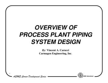
Step 2: Determine Heat LossesThere are several ways to determine the heat loss for pipes undera given set of design conditions: Heat loss calculations such as those detailed in IEEE Std515 (IEEE Standard for the Testing, Design, Installation,and Maintenance of Electrical Resistance Heat Tracing forIndustrial Applications). Computer-aided design programs that allow the userto input detailed information specific to an application.(Thermon’s CompuTrace design and selection programprovides this and more based on the formulas presentedin IEEE Std 515.) Heat loss charts based on selected pipe diameters,temperature differentials and insulation materials.This guide is based on heat loss charts derived from the formulaspresented in IEEE Std 515.1 The values shown in Tables 2.2through 2.7 are in watts per foot and are based on fiberglassinsulation.1. Select the heat loss chart which meets or exceeds2 thetemperature differential ( T) between the minimumambient and the maintain temperature.2. Based on the pipe diameter(s) of the application, readacross the table to the insulation thickness column tofind the heat loss under those conditions.For insulation materials other than fiberglass, use Table 2.1below to select the appropriate multiplier. If rigid insulationis used, select the heat loss for the next larger size of pipe toaccommodate the heating cable prior to applying the multiplier.3Table 2.2 Pipe Heat Loss @ 50 F 13.811.710.29.1Table 2.3 Pipe Heat Loss @ 100 F TPipeSizePreformed Pipe InsulationInsulation TypeMultiplierInsulation “k Factor”(Btu in/hr ft2 F) @ 68 al Wool0.950.238Calcium Silicate1.410.355Cellular Glass1.300.326Perlite1.800.455Notes1. Heat loss calculations are based on IEEE Std 515, Equation B.1, with the followingprovisions:Insulation 1½"Table 2.1 Alternate Insulation MultiplierInsulation 67.812"--27.518.915.112.7119.88.9 Piping insulated with glass fiber in accordance with ASTM Std C547.14"----2217.214.312.310.99.8 Pipes located outdoors in a 0 F ambient with a 25 mph wind.16"----24.819.41613.812.110.9 A 20% safety factor has been included.2. For situations where the T falls between two temperature ranges, linear interpolationcan be used to approximate the heat loss.3. When using flexible insulation on piping 1¼" in diameter and smaller, the insulation mustalso be one pipe size larger to accommodate the heating cable; i.e., use insulation sizedfor a 1" diameter pipe if the pipe to be insulated is ¾" -34.528.3242118.75
Complex Piping Design GuideFor Self-Regulating Heating CableTable 2.4 Pipe Heat Loss @ 150 F TPipeSize½"Table 2.6 Pipe Heat Loss @ 250 F TInsulation ThicknessPipeSizeInsulation 0"------95.778.566.858.452Table 2.7 Pipe Heat Loss @ 300 F TTable 2.5 Pipe Heat Loss @ 200 F "14"16"18"20"24"30"6Insulation 0.923.325.728.132.839.9PipeSize½"Insulation 530"------119.998.483.773.265.1
Step 3: Select the Proper Thermon Heating CableApply the temperature, electrical and heat loss informationgathered in Steps 1 and 2 to the items listed below to determinewhich Thermon self-regulating cable is best suited to the needs ofthe application. Table 3.1 compares numerous product featuresof Thermon’s BSX, RSX 15-2, HTSX, VSX-HT, and USX self-regulatingheating cables. Specific cable performance for BSX, RSX 15-2,HTSX, VSX-HT, and USX is detailed on pages 8-12.When the heat loss of the insulated pipe exceeds the output ofthe desired cable, consideration should be given to:a) using multiple passes of cable,b) switching to a higher power output cable, orc) decreasing the heat loss by increasing the insulationthickness or using an insulation with a lower “k factor”(see Table 2.1 Alternate Insulation Multiplier on page 5).Temperature Requirements The temperature informationgathered in Step 1 can now be applied to determine whichcable(s) meet or exceed the requirements. For installations inhazardous (classified) areas (see Approvals at right), the heatingcable may also be required to meet a temperature classificationrating, T-rating, to ensure safe operation even during an upsetcondition.Watt Density (Heat) Requirements The available watt densitiesare shown for each cable. These rated output values are basedon maintaining 50 F (10 C) when the cable is installed oninsulated metallic piping (using the procedures outlined in IEEEStd 515) at 120 and 240 Vac. Because the heat output of a selfregulating cable decreases with increasing temperatures, useGraphs 3.1 through 3.5 to determine the power output at themaintain temperature. Begin by finding the corresponding pipetemperature for a specific cable on the graph’s bottom axis.Where this temperature intersects the power output curve, readacross to the watts per foot (w/m) power output axis to identifythe heat output of the cable at a given temperature.Electrical Requirements The power supply system available foruse with heat tracing may leave few options available. Wherethere is a choice of voltage, the overall number of heat tracingcircuits might be reduced as longer circuit lengths are possiblewhen using the heating cables designed for nominal 240 Vacoperation. Similarly, the amperage rating of the branch circuitbreakers feeding power to the heat tracing can affect themaximum circuit length and, accordingly, the number of circuitsrequired for a system. Specific maximum circuit lengths areshown in Tables 3.5 and 3.6 (BSX and RSX 15-2), Tables 3.9 and3.12 (HTSX), Tables 3.16 and 3.17 (VSX-HT), and Tables 3.21 and3.22 (USX) based on circuit breaker size and start-up temperature(see Cold Start Impact).If the heating cable will be energized on a voltage other than 120or 240 Vac, use Tables 3.3 and 3.4 (BSX and RSX 15-2), Tables3.8 and 3.11 (HTSX), Tables 3.14 and 3.15 (VSX-HT), and Tables3.19 and 3.20 (USX) to locate the appropriate multiplier. Applythis multiplier to the watt density heat output value establishedusing Graphs 3.1 through 3.5.Cold Start Impact While a heat tracing system is generallydesigned to keep the contents of a pipe at the desired maintaintemperature, the cable may periodically be energized at lowertemperatures. The design of self-regulating cables requiresincreased heat output at lower temperatures; consequently,the start-up temperature for the heat tracing circuit must beconsidered when determining the maximum circuit length for agiven branch circuit breaker size.Approvals All Thermon self-regulating heating cables areapproved for use in ordinary (nonclassified) and hazardous(classified) locations. For specific approval information, refer tothe product specification sheets, Thermon Forms TEP0067 (BSX),TEP0048 (RSX 15-2), TEP0074 (HTSX), TEP0208 (VSX-HT) andTEP0239 (USX). For Class I, Division 1 applications in the UnitedStates, refer to Forms TEP0080 (D1-BSX), and TEP0077.Table 3.1 Suitability ComparisonBSXRSX 15-2HTSXVSX-HTUSX150 F (65 C)150 F (65 C)302 F (150 C)392 F (200 C)464 F (240 C)185 F (85 C)N/AN/A3, 5, 8 T610 T5185 F (85 C)N/AN/A400 F (204 C)482 F (250 C)482 F (250 C)400 F (204 C)450 F (232 C)482 F (250 C)464 F (240 C)482 F (250 C)482 F (250 C)T4A-T5T2C - T3T2C-T3T2C - T3Available Watt Densitiesw/ft @ 50 F (w/m @ 10 C)3, 5, 8, 10(10, 16, 26, 33)15(49)3, 6, 9, 12, 15, 20(10, 20, 30, 39, 49, 66)5, 10, 15, 20(16, 33, 49, 66)3, 6, 9, 12, 15, 20(10, 20, 30, 39, 49, 66)Steam Purge TolerantNoNoYesYesYesDielectric ymerFluoropolymerMetallic Braid MaterialTinned CopperTinned CopperNickel-Plated CopperNickel-Plated CopperNickel-Plated CopperOverjacket Material(s)Polyolefin or FluoropolymerPolyolefin or erMaximum Maintain Temperature/Max. Continuous Operating TemperatureMaximum Exposure TemperatureContinuous Power-OffIntermittent Power-OnIntermittent Power-OffT-Rating7
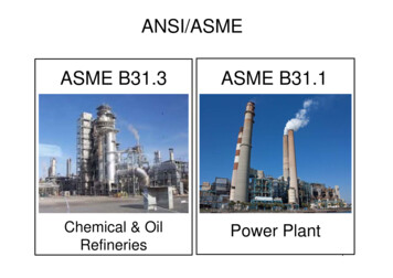
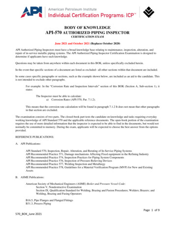
Complex Piping Design GuideFor Self-Regulating Heating CableBSX AND RSX 15-2 SELF-REGULATING CABLESThe power outputs shown in Table 3.2 and Graph 3.1 apply tocable installed on insulated metallic pipe at 120 and 240 Vac.When the heating cable will be operated on voltages other than120 and 240, use Table 3.3 for 120 Vac nominal cable and Table3.4 for 240 Vac nominal cable.Table 3.2 BSX and RSX 15-2 Power Outputs at 120 & 240 VacCatalog Number120 Vac NominalCatalog Number240 Vac NominalPower Outputat 50 F (10 C)W/ft (m)BSX 3-1BSX 3-23 (10)BSX 5-1BSX 5-25 (16)BSX 8-1BSX 8-28 (26)BSX 10-1BSX 10-210 (33)--RSX 15-215 (49)CIRCUIT BREAKER SIZINGMaximum circuit lengths for various circuit breaker amperagesare shown in Tables 3.5 and 3.6. Breaker sizing should be basedon the National Electrical Code, Canadian Electrical Code or anyother local or applicable code.The circuit lengths shown are for nominal voltages of 120 and 240Vac. While the power outputs will change based on the appliedvoltage, the circuit lengths will not significantly change; however,for detailed circuit information use CompuTrace.Table 3.5 BSX Circuit Length vs. Breaker Size (120 Vac)120 Vac Service VoltageCatalogNumberMax. Circuit Length vs. Breaker Sizeft (m)20A30A40A50 (10)360 (110)360 (110)360 (110)0 (-18)325 (99)360 (110)360 (110)-20 (-29)285 (87)360 (110)360 (110)-40 (-40)260 (79)360 (110)360 (110)50 (10)240 (73)300 (91)300 (91)0 (-18)205 (62)300 (91)300 (91)-20 (-29)185 (56)275 (84)295 (90)10(33)-40 (-40)165 (50)250 (76)265 (81)50 (10)190 (58)240 (73)240 (73)8(26)6(20)0 (-18)150 (46)225 (69)240 (73)-20 (-29)135 (41)200 (61)240 (73)-40 (-40)120 (37)180 (55)215 (66)50 (10)160 (49)200 (61)200 (61)0 (-18)110 (34)170 (52)200 (61)-20 (-29)100 (30)150 (46)200 (61)-40 (-40)90 (27)135 (41)180 (55)Graph 3.1 BSX and RSX 15-2 Power Output Curves at 120 & 240 VacBSX 3-118(59)16(52)12(39)Watts per Foot (W/m)Start-UpTemperature F ( C)RSX 15-2BSX 10BSX 5-1BSX 8BSX 8-1BSX 54(13)BSX 10-1BSX Pipe Temperature F ( C)Operating Voltage (Vac)110115120130BSX 3-10.900.931.01.07BSX 5-10.920.961.01.08BSX 8-10.910.961.01.08BSX 10-10.920.961.01.08Table 3.4 BSX and RSX 15-2 Power Output Multipliers (208-277 Vac)Catalog Number8240 Vac Service VoltageCatalogNumberTable 3.3 BSX Power Output Multipliers (110-130 Vac)Catalog NumberTable 3.6 BSX & RSX 15-2 Circuit Length vs. Breaker Size (240 Vac)BSX 3-2BSX 5-2BSX 8-2Operating Voltage (Vac)208220240277BSX 3-20.870.901.01.13BSX 5-20.880.921.01.12BSX 8-20.890.931.01.12BSX 10-20.890.931.01.12RSX 15-20.890.931.01.12BSX 10-2RSX 15-2Start-UpTemperature F ( C)50 (10)0 (-18)-20 (-29)-40 (-40)50 (10)0 (-18)-20 (-29)-40 (-40)50 (10)0 (-18)-20 (-29)-40 (-40)50 (10)0 (-18)-20 (-29)-40 (-40)50 (10)0 (-18)-20 (-29)-40 (-40)Max. Circuit Length vs. Breaker Sizeft (m)20A725 (221)650 (198)575 (175)515 (157)480 (146)395 (120)350 (107)315 (96)385 (117)285 (87)255 (78)230 (70)280 (85)225 (69)200 (61)180 (55)205 (63)145 (45)130 (40)120 (36)30A725 (221)725 (221)725 (221)725 (221)600 (183)590 (180)525 (160)475 (145)480 (146)425 (130)380 (122)345 (116)400 (122)340 (104)300 (91)275 (84)320 (98)225 (70)200 (62)180 (55)40A725 (221)725 (221)725 (221)725 (221)600 (183)600 (183)590 (180)530 (162)480 (146)480 (146)480 (146)430 (131)400 (122)400 (122)400 (122)365 (111)380 (116)315 (97)280 (86)250 (77)
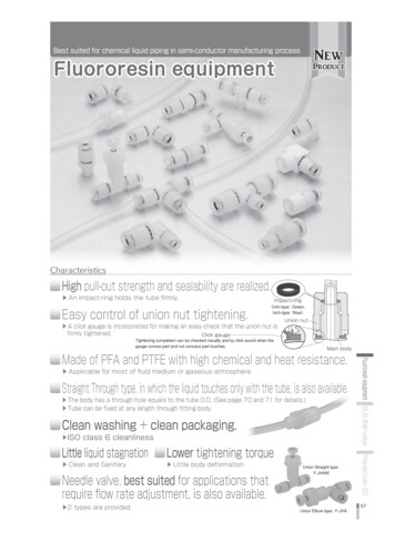
HTSX SELF-REGULATING CABLEENERGIZED AT 120 & 240 VACThe power outputs and temperature/power curves for HTSXcables rated for nominal voltage of 120 and 240 Vac are shownin Table 3.7 and Graph 3.2. For other voltages, use Tables 3.8and 3.9.Table 3.7 HTSX Power Outputs at 120 & 240 VacCatalog Number120 Vac NominalCatalog Number240 Vac NominalHTSX 3-1HTSX 3-2Power Outputat 50 F (10 C)W/ft (m)3 (10)HTSX 6-1HTSX 6-26 (20)HTSX 9-1HTSX 9-29 (30)HTSX 12-1HTSX 12-212 (39)HTSX 15-1HTSX 15-215 (49)HTSX 20-1HTSX 20-220 (66)22(72)18(59)Watts per Foot (W/m)Table 3.10 HTSX Circuit Length vs. Breaker Size (120 Vac)HTSX 3-1HTSX 6-1HTSX 2020(66)The circuit lengths shown are for nominal voltages of 120 and 240Vac. While the power outputs will change based on the appliedvoltage, the circuit lengths will not significantly change; however,for detailed circuit information use CompuTrace.120 Vac Service VoltageCatalogStart-UpNumberTemp. – F ( C)50 (10)Graph 3.2 HTSX Power Output Curves at 120 & 240 Vac24(79)HTSX CIRCUIT BREAKER SIZING 120 VACMaximum circuit lengths for various circuit breaker amperagesare shown in Tables 3.10 and 3.11. Breaker sizing should be basedon the National Electrical Code, Canadian Electrical Code or anyother local or applicable code.HTSX 9-1HTSX 1516(52)HTSX 12-114(46)HTSX 1212(39)HTSX 15-1HTSX 910(33)8(26)HTSX 66(20)HTSX 20-14(13)HTSX 3Max. Circuit Length vs. Breaker Size – ft (m)20A360 (109)30A360 (109)40A360 (109)0 (-18)360 (109)360 (109)360 (109)-20 (-29)360 (109)360 (109)360 (109)-40 (-40)360 (109)360 (109)360 (109)50 (10)235 (71)250 (77)250 (77)0 (-18)235 (71)250 (77)250 (77)-20 (-29)235 (71)250 (77)250 (77)-40 (-40)235 (71)250 (77)250 (77)50 (10)170 (52)205 (62)205 (62)0 (-18)170 (52)205 (62)205 (62)-20 (-29)170 (52)205 (62)205 (62)-40 (-40)165 (50)205 (62)205 (62)50 (10)135 (41)175 (54)175 (54)0 (-18)135 (41)175 (54)175 (54)-20 (-29)135 (41)175 (54)175 (54)-40 (-40)125 (38)175 (54)175 (54)50 (10)100 (30)160 (48)160 (49)0 (-18)95 (29)150 (46)160 (49)-20 (-29)90 (27)145 (44)160 (49)-40 (-40)85 (26)135 (41)160 (49)50 (10)85 (26)130 (40)140 (42)0 (-18)80 (24)120 (37)140 (42)-20 (-29)75 (23)115 (35)140 (42)-40 (-40)70 (21)110 (33)140 (42)Table 3.11 HTSX Circuit Length vs. Breaker Size (240 Vac)2(7)0(-18)50(10)100150200(38)(66)(93)Pipe Temperature F ( C)250(121)300(149)240 Vac Service VoltageCatalogStart-UpNumberTemp. – F ( C)50 (10)HTSX 3-2Table 3.8 HTSX Power Output Multipliers (110-130 Vac)Catalog NumberOperating Voltage (Vac)110115120130HTSX 6-2Max. Circuit Length vs. Breaker Size – ft (m)20A710 (217)30A710 (217)40A710 (217)0 (-18)700 (214)710 (217)710 (217)-20 (-29)615 (187)710 (217)710 (217)-40 (-40)530 (162)710 (217)710 (217)50 (10)470 (143)505 (154)505 (154)0 (-18)435 (132)505 (154)505 (154)-20 (-29)390 (120)505 (154)505 (154)HTSX 3-10.830.901.01.13-40 (-40)355 (108)505 (154)505 (154)HTSX 6-10.880.931.01.1250 (10)340 (104)410 (125)410 (125)HTSX 9-10.900.951.01.10HTSX 12-10.910.961.01.08HTSX 15-10.930.971.0HTSX 20-10.940.971.00 (-18)310 (95)410 (125)410 (125)-20 (-29)290 (88)410 (125)410 (125)1.07-40 (-40)265 (81)410 (125)410 (125)1.0550 (10)270 (82)355 (109)355 (109)0 (-18)245 (74)355 (109)355 (109)-20 (-29)230 (70)355 (109)355 (109)-40 (-40)215 (65)340 (104)355 (109)50 (10)200 (61)315 (96)315 (96)0 (-18)175 (53)275 (84)315 (96)315 (96)HTSX 9-2HTSX 12-2Table 3.9 HTSX Power Output Multipliers (208-277 Vac)Catalog NumberOperating Voltage (Vac)208220240277HTSX 3-20.800.871.01.27-20 (-29)165 (51)260 (79)HTSX 6-20.780.871.01.25-40 (-40)155 (48)245 (74)315 (96)HTSX 9-20.820.891.01.1850 (10)155 (48)245 (75)275 (84)HTSX 12-20.840.911.01.15HTSX 15-20.880.931.01.11HTSX 20-20.930.971.01.05HTSX 15-2HTSX 20-20 (-18)140 (42)215 (65)275 (84)-20 (-29)130 (40)205 (62)275 (84)-40 (-40)125 (38)190 (59)265 (80)9
Complex Piping Design GuideFor Self-Regulating Heating CableVSX-HT SELF-REGULATING CABLEThe power outputs shown in Table 3.12 and Graph 3.3 apply tocable installed on insulated metallic pipe at 120 and 240 Vac.When the heating cable will be operated on voltages other than120 and 240, use Table 3.13 for 120 Vac nominal cable and Table3.14 for 240 Vac nominal cable.Table 3.12 VSX-HT Power Outputs at 120 & 240 VacCatalog Number120 Vac NominalCatalog Number240 Vac NominalPower Outputat 50 F (10 C)W/ft (m)VSX-HT 5-1VSX-HT 5-25 (16)VSX-HT 10-1VSX-HT 10-210 (33)VSX-HT 15-1VSX-HT 15-215 (49)VSX-HT 20-1VSX-HT 20-220 (66)/ft]01825.00The circuit lengths shown are for nominal voltages of 120 and 240Vac. While the power outputs will change based on the appliedvoltage, the circuit lengths will not significantly change; however,for detailed circuit information use CompuTrace.Table 3.15 VSX-HT Circuit Length vs. Breaker Size (120 Vac)120 Vac Service VoltageCatalogNumberGraph 3.3 VSX-HT Power Output Curves at 120 & 240 VacVSX-HT 5-120(66)20.00Watts per Foot 11.080.940.820.690.580.460.360.250.160.06CIRCUIT BREAKER SIZINGMaximum circuit lengths for various circuit breaker amperagesare shown in Tables 3.15 and 3.16. Breaker sizing should be basedon the National Electrical Code, Canadian Electrical Code or anyother local or applicable code.VSX-HT 10-115 VSX-HT 20(49)15.0010(33)VSX-HT 1510.00VSX-HT 15-1VSX-HT 105.005(16)VSX-HT 505050(10)0.00100100(38)VSX-HT 20-1150150(66)200250300200250300(93)(121)(149)Pipe Temperatur
Complex Piping Design Guide For Self-Regulating Heating Cable 4 HEAT TRACING DESIGN OUTLINE The five steps below outline the design and selection process for an electric heat tracing system. The step-by-step procedures that follow the outline will provide the reader with the detailed information required