Transcription
Installation Operation ManualNatural Gas (NG) - Factory DefaultLiquid Propane Gas (LPG) - Optional Ori ceModel GU145 (S) / 508(11,12,21,22)1145 (S)Model GU195 (S) / 508(11,12,21,22)1195 (S)Model GU195 (M) / 508(11,12,21,22)1195 (M)CService Information Center:Call us first if you have any questions with this product. We can help you with questions about assemblyand Water Heater operation or if there are any damaged or missing parts when you unpack this unit from theshipping box. Please call before returning to the store.1-866-946-10968am-4pm CST, Monday through FridayIMPORTANT: Only specially trained and authorized personnel are permitted to service this water heater. NOTE TO ASSEMBLER / INSTALLER:Leave this manual with the consumer. NOTE TO CONSUMER: Keep this manual for future reference.RECORD YOUR SERIAL #(see silver CSA label on Gas Water Heater)!WARNING!Read this Operator's Manual carefully and be sure your Water Heater is properly assembled, installed andmaintained. Failure to follow these instructions exactly could result in re, explosion, serious bodily injury and/orproperty damage.Do not store or use gasoline or other ammable vapors and liquids in the vicinity of this or any other appliance.!WARNING!California Proposition 65 lists chemical substances known to the state to cause cancer, birth defects, death,serious illness or other reproductive harm. This product may contain such substances, be their origin from fuelcombustion (gas, oil) or components of the product itself.!WARNING!Only a licensed professional can install Eternal units for safety and code compliance. Venting and plumbingcodes can vary by location. Installation instructions and all applicable codes must be followed or propertydamage, severe injury, or death may result. Failure to use a licensed plumber or contractor, follow venting,plumbing, and building codes; or follow installation instructions may be unlawful and will void the productwarranty. Grand Hall is not responsible for any costs incurred for repairing any problems resulting from failure tofollow installation instructions or applicable codes.157140081P Date 2013/7/221
Table of ContentsIncluded & Optional AccessoriesP3SpecificationsP4DimensionsP5Parts & Service Parts ListP6 10Pre-Installation Instructions for Your SafetyP11Installation PreparationP12Condensate DisposalP13Indoor & Outdoor InstallationP14 15Mobile Home InstallationP16 18Wall & Floor MountingP19 20Venting Intake & Exhaust MaterialP21Venting Specification & EC Adapter InstallationP22Vertical & Horizontal TerminationP23 24Clearance Requirements from Vent Terminations to Building OpeningsP25Multiple Units TerminationP26Common Venting Installationmon Vent InstallationConcentric Vent Kit & Outdoor Vent Kit InstallationP27Vent Pipe Installation & Terminator PositionP29Gas Supply PipingP30LP ConversionP31Water Supply ConnectionP32Condensate PipingP33Temperature and Pressure Relief Valve & IPC For Recirculation ApplicationP34Electrical ConnectionP35Optional Remote Controller InstallationP36 37MCU InstallationP38 40Plumbing DiagramsP41 43Recovery Pump & Water Pipe SizeP44Operating InstructionsP45How To Use The Front Control InterfaceP46How To Use the Remote Controller & Ignition Cycle CounterP47Maintenance and ServiceP48"D" button Diagnostic FunctionP49DiagnosticsP50 52How To Check Gas CombustionP53 54Wiring and Connection DiagramP55 56Grand Hall Limited WarrantyP57 592P28
Included AccessoriesOptional AccessoriesSelf Tapping Screw5/32" x 5/8" : 2pcsPhilips Head ScrewM8x15 : 4pcsStainless Steel Expansion Bolt: 4pcs3
Eternal Hybrid Water Heater Technical Speci cationsModel NameGU145 / GU145(S)98% NG / 99% LP / 0.96 Energy FactorThermal Ef ciency (*) / Energy FactorInstallationFlue SystemGU195(S) / GU195(M)Indoor / Outdoor / Wall Hung / Floor StandingSealed Combustion Direct Vent / Power Vent ConvertibleVent Run3" PVCUp to 100ft, 6 Elbows Max, 5ft Deduction Per ElbowCondensate Discharge Low Fire / Med Fire / High Fire0.5GPH / 1.1GPH / 1.75GPHCondensate pH Level4 pHGas TypePre-set for NG / LP Conversion Kit IncludedUnit ConnectionsGas and Water3/4" Female NPTElectricityDedicated 120VAC, 60Hz w/3 Pronged Power CordGas Input RateMin / Max26,000 BTU/Hr / 145,000 BTU/Hr 26,000 BTU/Hr / 195,000 BTU/HrGas Supply Pressure NG / LP3.5" WC to 10.5" WC / 8" WC to 14" WCManifold PressureTime engineeringNG( ) 0.1" W.C.NG( ) 0.1" W.C.(minimum)Serial # (G902367 G1101155)PG( ) 0.1" W.C.PG( ) 0.1" W.C.Time engineeringNG(-) 0.02" W.C.NG(-) 0.02" W.C.PG(-) 0.02" W.C.PG(-) 0.02" W.C.Serial # (G1101156 G1111021)HoneywellNG(-) 0.01" W.C.NG(-) 0.01" W.C.Serial # (G1111022 )PG(-) 0.01" W.C.PG(-) 0.01" W.C.Ignition SystemDirect Electronic Ignition w/Automatic Flame SensingBurner SystemSingle Ori ce Premixed Fuel Injection Metal Fiber InfraredGas Valve SystemDual Stage Negative Pressure Full Modulation Air RatioInternal Piping MaterialStainless SteelReserve Tank2 GallonsElectrical ConsumptionStandby 8W, Max 45WStandby 8W, Max 85WMaximum Noise Level40dB (a)50dB (a)Remote ControllerUp to 3 kitsMulti Unit CapableUp to 2 in manifold, No Built - In MCU / M Option - MCU up to 8 UnitsGPM Capacity Range0.1 to 14.5 GPM0.1 to 19.5 GPMTemperature SensingTank, Cold Inlet, Hot Outlet, Air ThermistorsTemperature ControlSimulation Feed Forward and Feed Back, Computer Controlled Mixing ValveFlow SensingDual Flow Sensors w/Built-in GPM MonitorTemperature Settings Range100 F to 180 F Factory Limited to 140 F in 5 F StepsUnit Dimensions (WxHxD)16.9" x 29.1" x 13.8"Unit WeightSafety Devices83Ibs / M Option - 85IbsT&P Valve, Flame Rod, Thermal Fuse(306 F), Remaining FlameDetection, Fan RPM Check, Freeze Protection(-40 F), Vent BlockageDetection, Thermostat Switches(167 F / 194 F), Gas Valve CurrentLeak Detection, Ignition Prevention, Dipswitch Temperature Lock, GFCIw/2 x 5A Fuses.* GU145S and GU195S are for single or dual unit applications with no multi control unit. The GU195M is formultiple unit applications only and cannot be used for single unit applications.* Maximum manifold pressure is indicated on the rating label on right side of the unit.* Independent DOE tested.4
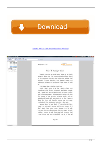
Dimensions - GU145(S) / 508(11,12,21,22)1145(S)GU195(S,M) / 508(11,12,21,22)1195(S,M)5
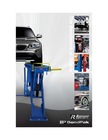
Parts Diagram for Model GU145(S) / 508(11,12,21,22)1145(S)GU195(S,M) / 508(11,12,21,22)1195(S,M)6
Parts Diagram for Model GU145(S) / 508(11,12,21,22)1145(S)7
Parts List for Model GU145(S) / 508(11,12,21,22)1145(S)KEYDESCRIPTION1Panel, Front Assembly2Panel, Top / Rear Assembly3Panel, Rear4Panel, Left Assembly5Panel, Right Assembly (GU145(S))6Panel, Bottom7Mounting Bracket8Wall Bracket9Controller / Front10T&P Relief Valve (Cash Acme)11Vent Collar12Vent Collar Packing13Rubber Foot14Drain Valve Assembly15Main Power Cord16Handle17Condensing Nipple18Mesh Screen19Outdoor Venting Cap (Optional)20Trap Cleaner Assembly21Radial Blower Assembly22Gas Valve23Air Pressure Switch (GU145(S))24Burner Assembly25Main Controller (GU145(S))26Cold Water Tube Assembly (GU145(S))27Hot Water Tube Assembly (GU145(S))28Flexible Silencer Kit29Mixing Valve30EC Adapter31Water Pressure Switch32Floater Valve8
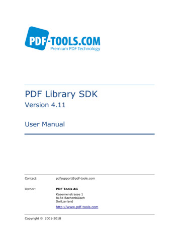
Parts Diagram for Model GU195(S) / 508(11,12,21,22)1195(S)Parts Diagram for Model GU195(M) / 508(11,12,21,22)1195(M)9
Parts List for Model GU195(S,M) / 508(11,12,21,22)1195(S,M)KEYDESCRIPTION1Panel, Front Assembly2Panel, Top / Rear Assembly3Panel, Rear4Panel, Left Assembly5Panel, Right Assembly (GU195(S,M))6Panel, Bottom7Mounting Bracket8Wall Bracket9Controller / Front10T&P Relief Valve (Cash Acme)11Vent Collar12Vent Collar Packing13Rubber Foot14Drain Valve Assembly15Main Power Cord16Handle17Condensing Nipple18Mesh Screen19Outdoor Venting Cap (Optional)20Trap Cleaner Assembly21Radial Blower Assembly22Gas Valve23Air Pressure Switch (GU195(S,M))24Burner Assembly25Main Controller (GU195(S,M))26Cold Water Tube Assembly (GU195(S,M))27Hot Water Tube Assembly (GU195(S,M))28Flexible Silencer Kit29Mixing Valve30EC Adapter31Water Pressure Switch32Floater Valve10
Pre-Installation Instructions for Your Safety!WARNING!If you do not follow these instructions exactly, a re or explosion could result causing property damage, personalinjury or loss of life.Installation Codes The installation must conform with local codes or, in the absence of local codes, with National Fuel Gas Code,ANSI Z223.1/NFPA 54. Properly ground the unit in accordance with all local codes or in the absence of local codes, with the NationalElectrical Codes, ANSI/NFPA 70.Before Installation This water heater does not have a pilot. It is equipped with an ignition device that automatically lights the burner.Do not try to light the burner by hand. Smell all around the water heater area for evidence of leaking gas. Be sure to smell next to the oor because LPgas is heavier than air and will settle on the oor. Use only your hand to turn the manual gas valve knob. Never use tools. If the knob will not turn by hand, don't tryto repair it. Call a quali ed service technician. Force or attempted repair could result in a re or explosion. Do not use this water heater if any part has been under water. Immediately call a quali ed service technician toinspect the water heater and to replace any damaged parts.!WARNING!WHAT TO DO IF YOU SMELL GAS Do not try to light any appliance. Do not touch any electrical switch; do not use any phone in your building. Immediately call your gas supplier from a neighbor's phone. Follow the gas supplier's instructions. If you cannot reach your gas supplier, call the re department.TO TURN OFF GAS TO WATER HEATER Turn off all electrical power to the water heater if service is to be performed. Turn the manual gas valve located on the outside of the unit clockwise to the off position.Vapors from ammable liquids will explode and catch re causing death or severe burns. Do not use or store ammable products such as gasoline, solvents or adhesives in the same room or area near the water heater.Keep ammable products Far away from water heater In approved containers Tightly closed Out of children's reachVapors Cannot be seen Vapors are heavier than air Go a long way on the oor Can be carried from other rooms to the main burner by air currents!WARNING!Use this water heater at your own risk. The set outlet water temperature can cause severe burns instantlyor death from scalds. Test the water before bathing or showering. Do not leave children or the in rm withoutsupervision.!NOTE!Each eternal is equipped with a computer controlled mixing valve to ensure precise temperature is beingdelivered. Modulation noise is normal and should not be of concern.11
Installation PreparationUnpacking Your Eternal Water Heater Unpack the unit carefully and make sure that all accessories are put aside so they will not be lost. Operator's manual Warranty Registration Card Included Parts Inspect the water heater for possible shipping damages.Additional Safety Instructions Check the markings of the rating plate on the water heater to be certain the type of gas being furnishedcorresponds to what the water heater is equipped for. Do not connect this water heater to a fuel type not in accordance with the rating plate. Read the Safety guidelines in the beginning of this manual. The internal computer controlled regulator is preset by the manufacturer and should not be adjusted by user. Maintain proper space around the unit for servicing. Install the unit so that it can be connected or removedeasily. The electrical connection requires a means for switching off the power supply. Avoid installing the unit in an area with high levels of dust, sand, or debris. These particles may clog the airvent or impair the function of the fan, leading to improper combustion. Regular maintenance is needed. Do not install the unit where the exhaust vent is pointing into any opening in a building or where the noise maydisturb neighbors.WATER HEATER PLACEMENT Carefully choose the location for the new heater as placement is a very important consideration for the safety ofthe occupants in the building and for the most economical use of the appliance. Whether replacing an old water heater or putting the water heater in a new location, consider the following criticalpoints: The location selected should be as close to the vent termination point as possible, and centered within thewater piping system for best hot water delivery. All water heaters can leak. Do not install without adequatedrainage provisions where water flow can cause property damage. If vented through an outside wall or through the roof using 3" vent piping the total vent run cannot exceed 95feet with one 90 elbow. If more elbows are required the venting distance must be reduced 5 feet for every 90 elbow. Vent piping should slope downward towards the unit. Horizontal runs require adequate support at 3½ feetintervals and vertical runs supported at 5 feet intervals. Condensation may be created at times as the combustion gases exit the vent cap. Discoloration of surfaces inproximity to the vent cap may occur.!CAUTION!!Before Commencing The InstallationCheck that it is in accordance with relevant buildingand mechanical codes, as well as any local, state orfederal regulations.!CAUTION!The drain valve must be tightened byHand ONLY, not by tools of any kind.WARNING! The appliance should be located in an area where leakage of the tank or connections will not result in damageto the area adjacent to the appliance or to lower floors of the structure. When such locations cannot beavoided, it is recommended that a suitable drain pan be installed under the appliance. The pan must not restrictcombustion air ow. The minimum inlet gas pressure must be within the value speci ed by the manufacturer and the minimum valuelisted is only for the purpose of input adjustment. If a water heater is installed in a closed water supply system, such as one having a back ow preventer in thecold water supply line and a thermal expansion tank is required, contact the water supplier or local plumbinginspector on how to control this situation. The Temperature and Pressure (T&P) relief valve must be certi ed as meeting the requirement of the Standardfor Relief Valves and Automatic Gas Shut-off Devices for Hot Water Supply Systems ANSI Z21.22/CAN14.4. The valve must be marked with a maximum set pressure not to exceed the marked hydrostatic workingpressure of the water heater (150 psi) and a discharge capacity not less than the water heater input rate asmarked on the rating plate.12
Condensate DisposalCAUTION!!The condensate drain must be lled and unobstructed to allow ow of condensate. The condensate should notbe subjected to conditions where freezing could occur. If the condensate is subjected to freezing or obstruction, itcan leak, resulting in potential water damage to the unit and surrounding area.The condensate trap must be lled with water prior to using the water heater. Pour water down the exhaust collar until water visibly ows out of condensate drain before rst use.Figure 1.NOTE!!The drain line material must be a material approved by the authority having jurisdiction. In absence of suchauthority, PVC and CPVC piping must comply with ASTM D1785 or D2846. This pipe must be connected to theport at the side panel. The end of the pipe should drain to a laundry tub or to a oor drain.1/2" PVC (SCH40, ASTM-D1785)or3/4" CPVC (SDR11, ASTM-D2846)Figure 2.!NOTE!Eternal water heater will typically produce a condensate that is considered slightly acidic with a Ph content ofapproximately 3-4. Install a neutralizing lter if required by authority having jurisdiction (See gure 2).1. Direct to drain from the unit.2. Drain through neutralizer from the unit.3. Drain to laundry tub from the unit, in this case the unit must be above the height of the laundry tub.4. When installing a condensate pump, ensure the pump is approved for use with condensing appliance.The pump should be equipped with an over ow switch to prevent property damage from potential condensatespillage.CLEANING OUT THE TRAPOver time, blockage of the trap by debris may occur; when the condensate cannot be released, the unit will go intoerror and will shut down. When this occurs, the trap must be cleaned.To Remove Trap1. Gently pull trap body downwards to remove.2. Remove clip securing trap to the nipple.13Figure 3.
Indoor InstallationClearancesFrom top of water heater12 inchesFrom front of unit6 inches (*) From left side of unit (gas piping side) 6 inchesFrom side wall ue or vent connector in any direction 6 inchesFrom back of unitFrom right side of unit0.6 inch2 inches*For accessibility when performing maintenance, 24" clearance in front of the unit it is recommended.Combustion Air Supply GU145(S) / GU195(S,M) can be used as either Power-Vent or Direct-Vent appliance. When used as a PowerVent appliance, the water heater should be located in an area where enough air is available for propercombustion and ventilation. Follow the latest edition of ANSI Z223.1 and any of your local codes that areapplicable. GU145(S) / GU195(S,M) is a Category IV vented appliance and manufacturer's ventilation specifications shouldbe followed. In general these requirements specify that if the unit is installed in a confined space, there must be permanent airsupply openings if Eternal isn't installed as Direct-Vent.!WARNING - high elevation installations!Natural gas in high altitude might contain less heating value than typical 1100 BTU/ cuft and therefore can causeimproper air / gas mix leading to improper combustion. For natural gas installations in altitudes above 3,000 feet,be sure to apply the intake ori ce (P/N 152140230) provided by manufacturer in the accessory box.Minimum Recommended Air Supply To Water Heater as Power-VentModel #Water Heater CapacityOutside Air AreaInside Air AreaGU195 (S,M)Max. 195,000 Btu/hour14 sq.in.54 sq.in.GU145 (S)Max. 145,000 Btu/hour10 sq.in.40 sq.in.Air supply from outside building:When combustion air is supplied directly through an outside wall such as intake louver openings into the dwelling,each opening should give a minimum free area of one square inch per 15,000 Btu/hour of the total input ratings ofall appliances in the enclosed area.Air VentsHeaterAir supply from inside building:When combustion air is supplied from inside the building, each opening should give a minimum free area of onesquare inch per 3,750 Btu/hour of the total input ratings of all appliances in the enclosed area. These openingsshould never be less than 40 sq.in.Air VentsHeaterThe minimum required inside air volume should be 50 cu.ft per every 3,750 Btu/hour.Model #Water Heater CapacityMinimum Required Air VolumeGU195 (S,M)Max. 195,000 Btu/hour2649 cu.ftGU145 (S)Max. 145,000 Btu/hour1932 cu.ft14
Outdoor InstallationClearancesFrom top of water heater24 inches From back of unitFrom front of unit24 inches From left side of unit (gas piping side) 6 inchesFrom side wall ue or vent connector in any direction 6 inchesFrom right side of unit0.6 inch2 inchesIf this unit is installed under an overhang, there must be a 24" clearance from the top of the unit to the overhang,and the surrounding area must be open in front and on the sides of the unit.Exhaust Ventilation For outdoor installation, do not remove the vent cap from the top of the appliance. Locate the water heater in anopen, unroofed area, and maintain the above minimum clearances from combustible materials.!WARNING!Do not have the ue terminal pointing toward an opening into the building. Do not locate your heater in a pit orany location where gas and water can accumulate.!WARNING!Do not install the water heater where water, debris or ammable vapors may get into the ue terminal. This maycause damage to the water heater.Min. 4ft!WARNING - high elevation installations! Natural gas in high altitude might contain less heating value than typical 1100 BTU/ cuft and therefore cancause improper air / gas mix leading to improper combustion. For natural gas installations in altitudes above3,000 feet, be sure to apply the intake ori ce (P/N 152140230) provided by manufacturer in the accessory box. Dipswitch setting for high altitude is different to sea level installation, Please call 1-866-946-1096 to speak to aservice technican for proper con guration.15
Mobile Home InstallationWARNING!!Read and Review this entire Manual with special emphasis on combustion and ventilation for your safety.If you do not follow these instructions exactly, a re or explosion could result causing property damage, personal injuryor loss of life.Eternal water heater must be used as a sealed combustion type (Direct Vent) where all the combustion air is suppliedfrom the outdoors through the air intake and all combusted gas byproduct is vented directly to the outside by means ofthe vent termination.MOBILE HOME (Manufactured Home).This appliance must be installed in accordance with the Manufactured Home Construction And Safety Standard,(Title 24,CFR; Part 3280). In addition, install in accordance with the following instructions, the instructions supplied with the ventingtermination, local codes, utility company requirements for the installation of water heaters in manufactured homes (mobilehomes). In the absence of such a standard, the water heater should be installed in accordance with the latest edition ofthe National Fuel Gas Code, ANSI Z223.1/NFPA 54 and ANSI A119.5/NFPA 501D.Wall mount the water heater with the brackets providedWARNING!! The water heater must be properly supported; if the wall is not strong enough, be sure to reinforce the wall.The unit must be mounted on a vertical wall and level to the ground. Wall mount may caused noises and vibration to magnify through the wall; carefully select where to mount the unit isimportant. In some cases, oor mount should be considered.Mounting Steps1. Install mounting brackets with 6 screws on top and bottom back of the unit.Philips Head Screws1/4"x3/8"Philips Head Screws1/4"x3/8"2. Select a location on the wall to mount the unit. The included wall bracket has been pre-drilled for easy installation onstandard wall studs. If the framing is not standard or installing on an uneven surface, fasten 3/4" plywood to the studwall and then attach the wall bracket.1/4"x1 ½" Screws3. Hang the unit on the mounted wall bracket and secure bottom of the unit to the wall with included wall anchors and wallscrews.1/4"x1 ½" ScrewsWall Mounting For Commercial Food ServicePer ANSI / NSF-5, the unit must be mounted at least 6" above the oor from the base of the unit.This mounting clearance provides access for clearing any possible debris or accumulated water seepage that can occurbelow the unit.6"16
Mobile Home InstallationProper material for Intake and Exhaust ventWARNING!!This water heater must be properly vented for removal of exhaust gases to the outside of the home. Correct installationof the vent pipe system is mandatory for the safe and ef cient operation of this water heater and is an important factorin the life of the unit.Vent Pipe MaterialThe appliance must be vented separately from all other appliances. The following type of non-metallic vent can be used: PVC (schedule 40, ASTM-D1785) CPVC (schedule 40, ASTM-D2846) PVC-DWV (ANSI/ASTM-D2665) ABS (schedule 40, ASTM-D2661) Polypropylene Pipe Single wall & Components (ULC-S636, UL-1738)Note : Do not use cellular foam core pipe.Cementing PVC, ABS or CPVC PIPE and FITTINGAll primers, cleaners and cements must meet all local codes and applicable standards of the American Society for TestingMaterials (ASTM).Gas leak be conducted for supply pressures above 1/2psig.To install the proper venting for the water heater in a Mobile Home (Manufactured Home)Per code, water heaters must be installed with a sealed combustion design so as to separate the water heater'scombustion and venting system from the interior atmosphere of the manufactured home. In accordance with code - waterheaters must be direct vented. Please refer to direct venting instructions and diagrams on page 23-24.Horizontal TerminationVertical TerminationBelow diagrams are examples of vertical terminations. Through roof (Direct Vent) Through roof (Concentric Vent)Below diagrams are examples of vertical terminations. Side Wall (Direct Vent) Side Wall (Power Vent)!! Through roof (Power Vent)WARNING!The Grand Hall approved concentrickit is a unique pipe-in-pipe ventingsystem designed for termination. Donot try to replicate or make your own.For more information, please refer toConcentric Vent Kit section in theOperation manual. Side Wall (Concentric Vent)An open tee is optional but recommendedto use as a termination to alleviate andprevent back pressure in the ventingsystem.!WARNINGWARNING!The Grand Hall approvedconcentric kit is a unique pipein-pipe venting system designedf or t er min at ion. D o not t ry t oreplicate or make your own. Formore information, please refer toConcentric Vent Kit section in theOperation manual.An open tee is optional butrecommended to use asa termination to alleviateand prevent back pressurein the venting system.For optimal results theopen tee should bepositioned vertically.! Pipes must terminate a minimumo f t w el v e ( 1 2) in c h es a bo v eanticipated snow level. It cannot be connected to existingvent piping or chimney. The total vertical and horizontalruns cannot exceed the maximumlength with a maximum number of90 degree elbows as speci ed inthe table of page 22. Eternal can be vented straightup and a horizontal section is notrequired for vertical terminations.!WARNING! Once the vent terminal location has been determined, make a holethrough the exterior wall to accommodate the vent pipe. Vent pipe mustonly exit exterior wall horizontally. Place the 1/2" metal mesh screen inside the terminal tting and connectit as shown to the vent pipe on the exterior of the building. Seal any opening around the vent pipe or ttings with mortar or siliconecaulk "as shown" above. Complete the rest of the vent pipe installation to the water heater's ventconnector tting on the blower outlet.If necessary support horizontal run as previously mentioned.17
Mobile Home InstallationLOCATION for MOBILE HOME (Manufactured Home)."MUST BE INSTALLED UNDER DIRECT VENT ONLY"Placement of Water Heater: Locate the water heater as desired, make certain the minimum clearances are maintained.For indoor and outdoor installation follow entire Eternal operation manual, please see section above on mobile home."When installing in a garage, the heater's ignition source should be elevated no less the 18" from the oor."This operation Manual should be kept by the unit after installation.ClearancesFrom top of water heater12 inchesFrom back of unitFrom front of unit6 inches (*) From left side of unit (gas piping side)From side wall ue or vent connector in any direction6 inchesFrom right side of unit*For accessibility when performing maintenance, 24" clearance in front of the unit it is recommended.0.6 inch6 inches2 inchesTo convert a Unit from Natural gas to LP or LP to Natural gasNOTE!!Contact the local propane gas supplier for recommended sizing of piping, tanks and 100% lockup gas regulator. Adjust the propane supply regulator provided by the gas supplier for 13" w.c. maximum pressure.NOTE!!LP conversion kit (LP Orifice, PROPANE GAS Label) must be ordered from Grand Hall USA. Conversion can only becompleted by a qualified professional.How to convert to LP1. Remove front panel by loosening 5 screws.4. Insert LP orifice into the nozzle, retighten gas tubeand make sure no gas leak.LP Ori ceGas Tube5. Reassemble the front panel and apply the LP label whichis in the accessory kit.ScrewsLP label2. Locate the gas valve towards lower left of the unit.!WARNING!Prior to start up, ensure the unit is set to re propane.Check the rating label for the type of fuel. If there is acon ict or doubt on the setup, remove the gas valveand check for the propane ori ce. Failure to ensureproper setup could result in severe personal injury,death or substantial property damage.Gas Valve3. Loosen nut connecting gas tube to gas valve.To convert back from LP to Natural GasAll Eternal models come factory pre-con gured as Naturalgas, However if the water heater has been converted toLP and needs to be converted back to Natural gas, followsteps 1, 2, 3 and remove the LP ori ce and the LP Label.Nut18
Wall MountingWARNING!! The water heater must be properly supported; if the wall is not strong enough, be sure to reinforce the wall.The unit must be mounted on a vertical wall and level to the ground. Wall mount may caused noises and vibration to magnify through the wall; carefully select where to mount theunit is important. In some cases, oor mount should be considered.Mounting Steps1. Install mounting brackets with 6 screws on top and bottom back of the unit.Philips Head Screws1/4"x3/8"Philips Head Screws1/4"x3/8"2. Select a location on the wall to mount the unit. The included wall bracket has been pre-drilled for easy installationon standard wall studs. If the framing is not standard or installing on an uneven surface, fasten 3/4" plywood tothe stud wall and then attach the wall bracket.1/4"x1 ½" Screws3. Hang the unit on the mounted wall bracket and secure bottom of the unit to the wall with included wall anchorsand wall screws.1/4"x1 ½" ScrewsWall Mounting For Commercial Food ServicePer ANSI / NSF-5, the unit must be mounted at least 6" above the oor from the base of the unit.This mounting clearance provides access for clearing any possible debris or accumulated water seepage that canoccur below the unit.6"19
Floor MountingStanding Installation GU145(S) / GU195(S,M) can be installed standing on combustible floor surface, or on a water heater stand. Be sure to use a suitable draining pan under the unit if leakage of the tank or connections will resuit in damage tothe area adjacen
Eternal Hybrid Water Heater Technical Speci cations Model Name GU145 / GU145(S) GU195(S) / GU195(M) . GU145S and GU195S are for single or dual unit applications with no multi control unit. The GU195M is for . inspect the water heater and to replace any damaged parts. Far away from water heater In approved containers