Transcription
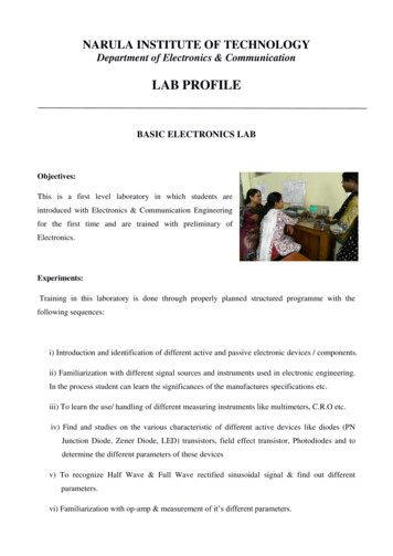
NARULA INSTITUTE OF TECHNOLOGYDepartment of Electronics & CommunicationLAB PROFILEBASIC ELECTRONICS LABObjectives:This is a first level laboratory in which students areintroduced with Electronics & Communication Engineeringfor the first time and are trained with preliminary ofElectronics.Experiments:Training in this laboratory is done through properly planned structured programme with thefollowing sequences:i) Introduction and identification of different active and passive electronic devices / components.ii) Familiarization with different signal sources and instruments used in electronic engineering.In the process student can learn the significances of the manufactures specifications etc.iii) To learn the use/ handling of different measuring instruments like multimeters, C.R.O etc.iv) Find and studies on the various characteristic of different active devices like diodes (PNJunction Diode, Zener Diode, LED) transistors, field effect transistor, Photodiodes and todetermine the different parameters of these devicesv) To recognize Half Wave & Full Wave rectified sinusoidal signal & find out differentparameters.vi) Familiarization with op-amp & measurement of it’s different parameters.
vii) Implementation of different logic gates & Boolean functions using different Ics.Facilities available:1. In this laboratory there are sufficient number of working benches (nearly 10), so that thestudents can work comfortably. Each of the benches are fully equipped with:a) Signal sourcesb) Power supplyc) Measuring instruments like digital multimeter, C.R.O etc.2. There are two working benches are set aside for assembly of circuits, with facilities of solderingand desoldering, electronic tool kits etc.Major Equipment in the Lab1. Various power supplies – fixed and variable variety with different current rating. Make –Enova, Aplab etc. Some of the power supply are in use designed and fabricated technicalstaff of the department.2. Digital multimeters (Mastech ,Vartech)3. Cathode ray oscilloscope (Scientech)4. Function Generator (Scientech)5. Regulated DC power supply (Scientech)6. FET Test Set (Detech, Scientech- Nvis Technologies)7. PN Junction Diode / Zener Diode Test Set (Detech, Scientech- Nvis Technologies)
8. Op-Amp Power Supply (Sushma Electronics)9. Rectifier Test Set (Detech, Scientech- Nvis Technologies)10. Op-Amp Test Set (Microtech Industry)11 Transistor Test Set (Detech, Scientech- Nvis Technologies)12 Multi power Supply (Scientech)General information about the laboratories:1. Before starting of the laboratory the students are instructed with necessary safety andprecautionary measures that has to be adopted in any electrical laboratory.2. Well designed laboratory manual / instruction sheets are provided to students at thebeginning of the session for a particular lab.3. Laboratory is maintained and conducted by well trained technical supporting staff under thesupervision of the faculty members.4. Most of the technical staffs have undergone first aid and fire fighting training.
DIGITAL ELECTRONICS LABObjectives:Digital Electronics is technology subject which isintended to make students familiar with differenttypes of designs as sequential logic circuits,combinational logic circuits, trouble shooting ofvarious digital systems & study of various digitalsystems. Knowledge of basic electronics & digitaltechniques is useful in understanding theory andpracticals of the subjects. For years, applications ofdigital electronics were confined to computer systems. Today digitalelectronics are applied inmany diverse areas such as telephony, data processing, radar, navigation, military systems, medicalinstruments, process controls etc.Experiments:In this laboratory students are introduced with digital ICs and their specifications and are skilledwith practical digital circuit design. Training in this laboratory is done with accurate plannedstructured programme with the following sequences:i) Introduction and identification of different digital IC chips and their specifications, concept of Vccand ground, verification of the truth tables of logic gates.ii) To learn the use of different ICs and LEDs for designing logic circuit and verifying the resultsrespectively.iii) Study of basic gate diagrams and realize the same with universal logic gates .iv) Realization of different codes and also the conversion technique like BCD to Excess-3 and viceversa, BCD to decimal to drive 7-segment display using multiplexer etc.v) Construction of various combinational circuits such as adder, adder circuit using shift Register
and full adder, subtractor, simple decoder, multiplexer, parity generator and comparator using logicgate ICs or any specific chip.vi) Study of the difference between combinational and sequential circuit and realize the need offunction generator,CRO for the design of sequential circuits like RS-JK and D flip-flops usinguniversal logic gates; universal Register using JK flip-flops and logic gates or using multiplexer andflip-flops ; asynchronous & synchronous up/down counter; ring counter and johnson’s countersequential counter with irregular sequences etc.Facilities available:Sufficient number working benches (more than 8) are there in this laboratory for the easiness ofstudents work. Each of the benches are fully equipped with:i) Power supplyii) Function Generatoriii) C.R.O etc.Major Equipment in the Lab1.Fixed and variable Various power supplies (Elnova, Aplab)2.Multiple power supply (Scientech)3.Digital multimeters (Metravi,Mastech)4.Function generators: (Aplab,Systronics,Intilect,Scientech)5.Cathode ray oscilloscope (Aplab)6.IC Tester:7.Digital IC Tester (Minmax Electronics)8.Analog IC Tester (Minmax Electronics)General information about the laboratories:1. Before starting of the laboratory the students are instructed with necessary safety and
precautionary measures that has to be adopted in any electrical laboratory.2. Well designed laboratory manual / instruction sheets are provided to students at thebeginning of the session for a particular lab.3. Laboratory is maintained and conducted by well trained technical supporting staff under thesupervision of the faculty members.4. Most of the technical staffs have undergone first aid and fire fighting training.
ANALOG ELECTRONICS LABObjective:The laboratory introduces students to practical,circuit design and contributes significantly toprovide them with engineering skills. Theexperiments covered in this laboratory aresynchronized with its theoretical part, so thatstudents might be able to understand the practicalaspects of it. Students can build simple circuits byunderstanding electronics schematics and setworking prototype circuits. The purpose is toteach analog circuit design theory and to give the student an understanding of the factors governingthe behavior of electronic circuits. Topics covered also demonstrate the need for strong electroniccomponent in other scientific and engineering fields. The students are encouraged to analyze therequirements and determine the fundamental criteria of sound circuit design the main intention ofthis laboratory is to give introduction to different steps used in the design of electronic systemsaccording to industrial standards.Experiments:In this laboratory students are introduce to design, assembly, testing, and trouble-shooting of analogelectronic circuits. Experiments encompass a wide range of topics such as amplifiers, filters, powersupplies, power control, oscillators, and communication circuits. In this laboratory experiments aredone through following planned sequences:1) Learn the various applications of diode like-clipper, clamper, full wave rectifier etc.2) Study voltage regulator using Zener diode and measure ripple and regulation characteristicswithout and with capacitor filter.3) Find and studies on the various characteristic of B.J.T & F.E.T and to determine their differentparameters.
4) Study some important aspects of different power amplifiers configurations.Eg.- class A & class B, class C & Push-Pull amplifiers5) Design a two-stage R-C coupled amplifier & study of its gain & Bandwidth.6) Realization of different applications of operational amplifier - current mirror, level shifter circuit& V-to-I , I-to-V converter,.7) Find and studies the different configuration of multivibrators using NE 5558) Design and construct switched mode power supply, voltage regulator using regulator IC chip9) Construction of simple function generator using IC chip.10) Study of a digital to analog converter and vice versa.Facilities available:1. In this laboratory there are sufficient number working benches (nearly 10), so that the studentscan work comfortably. Each of the benches are fully equipped with:a) Function generatorb) Power supplyc) Measuring instruments like digital multimeter, Cathode Ray oscilloscope, LCR meter etc.2. There are two working benches are set aside for assembly of circuits, with facilities of solderingand disordering, and other testing equipments like DSO, Power meter etc which are mainly usedfor project and some innovative experiments.Major Equipment in the Lab1) Function generator- (Scientech)2) Variable Power supply: fixed and variable variety with different current rating. Make – Elnova,Scientech etc. Some of the power supply is in use designed and fabricated by students and technicalstaff of the department.
3) Digital multimeters ( Mastech-M3900)4) Oscilloscopei) Cathode Ray Oscilloscope. (25MHz, 30 MHz, scientech)ii)Digital Storage Oscilloscope. (100MHz, scientech)5) L.C.R Meter(Aplab).6) Distortion Meter(Scientech).7) Output Power Meter. (Scientech)8) Trainer Kit.a) Transistor Push Pull Amplifier. (Omega)b) Switch Mode Power Supply.Nvis technologiesc) Analog To Digital Converter. (Scientech)d) Digital To Analog Converter. (Scientech)e) V.C.O & PLL. (Scientech)f) Tuned Amplifier. (Scientech)g) Push Pull Amplifier.(Scientech)h) Class A Amplifier. (Scientech)i) Class B Amplifier. (Scientech)j) Class C Tuned Amplifier. (Scientech)k) Transistor Characteristics Trainer. ( Nvis technologies)General information about the laboratories:1. Before starting of the laboratory the students are instructed with necessary safety andprecautionary measures that has to be adopted in any electrical laboratory.2. Well designed laboratory manual / instruction sheets are provided to students at thebeginning of the session for a particular lab.
3. Laboratory is maintained and conducted by well trained technical supporting staff under thesupervision of the faculty members.4. Most of the technical staffs have undergone first aid and fire fighting training.5.Laboratory is equipped with and Emergency Power Off System.6. All students, are advised to obey the dos’ and don’ts mention in the lab.
MICROPROCESSOR AND MICROCONTROLLER ocessors and microelectronics in generalhave brought about a revolution in computerscience, manufacturing, telecommunications aswell as in space and high-energy physics. Inview of the impact of this new technology .Inrecent years the Laboratory has organized andprovided support not only to courses strictlyrelated to Microprocessors, but also to otheractivities related to telematics, programming of real-time systems, data acquisition systems, digitalsignal processing and scientific instrumentation. The goals of this lab is to supplement the theorycourse (Microprocessor and Micro-controller) to assist the students in obtaining a ndMicro-controllerarchitecture,programming ,and application part to provide experience in analyzing and test of Microprocessorand Micro-controller using trainer kits .The basic function of these lab is :- To understand basic theories of Microprocessor and Micro-controller system-To learn the programming of Microprocessor and Microcontrollers.- To understand the applications Microprocessor and Micro-controller anddifferent peripheral systems.Experiments:i) Study of prewritten programs on trainer kit using the basic instruction set (data transfer,Load/Store, Arithmetic, Logical).ii) Familiarization with 8085 simulator on PCiii) Programming using kit and simulator for:a) Table look upb) Copying a block of memory
c) Shifting a block of memoryd) Packing and unpacking of BCD numberse) Addition of BCD numbersf) Binary to ASCII conversiong) String Matching Multiplication using Booth’s Algorithmiv) Program using subroutine calls and IN/OUT instructions using 8255 PPI on the trainerkit e.g. subroutine for delay, reading switch state and glowing LEDs accordinglyv) Study of timing diagram of an instruction on oscilloscope .vi) Keyboard and Multi-digit Display with multiplexing using 8255vii) Study of 8051 Micro controller kit and writing programs for Interfacing of Keyboard, DAC andADC using the kit.viii)Serial communication between two trainer kits .Facilities available:I. In this laboratory there are sufficient number working benches (more than 10), so that the studentscan work comfortably. Each of the benches are fully equipped with:Sl no.Name of the equipmentModel no.18085 Microprocessor trainer kitESA 85-228085 Microprocessor trainer kitVMC 850138051 Microcontroller trainer kitVMC 51 LCD48085 Microprocessor trainer kit85-0458085 Microprocessor trainer kitSBSI68051 Microcontroller trainer kitSilicon7Seven segment display interface moduleVMC 8501&51LCD8DC motor interface moduleVMC 8501&51LCD
9Stepper motor interface moduleVMC 8501&51LCD10EPROM Eraser-General information about the laboratories:1. Before starting of the laboratory the students are instructed with necessary safety andprecautionary measures that has to be adopted in any electrical laboratory.2. Well designed laboratory manual / instruction sheets are provided to students at thebeginning of the session for a particular lab.3. Laboratory is maintained and conducted by well trained technical supporting staff under thesupervision of the faculty members.4. Most of the technical staffs have undergone first aid and fire fighting training.
SIGNALS & SYSTEMS LABObjective:The Signals and Systems is concerned with therepresentation of signals and the study of thechanges that occur to them as they pass throughsystems. The study of Signals and Systems is toallow one to predict, with some certainty, thebehaviour of systems when they are subjected todifferent input signals. The problem solving andanalytical skills that the student acquires throughthe study of the subject can often help him in hislater career to tackle and solve problems in a systematic manner.Looking ahead, the scope of potential applications of the methods of Signals and Systems willcontinue to grow as engineers are faced with new challenges involving ever more complex systemsand processes.Experiments:Software part1. Students can visualize the Z-domain analysis of: a) Sinusoidal signals b) Step functions.2. Verify the output of Fourier and Laplace transformations of a signal.3. To study convolution theorem in time and frequency domain.4. To Study Signal Synthesis via sum of harmonics.Hardware part1. To study LPF &HPF, band passes and rejects filters using RC circuits.2. To demonstrate how analog signals are sampled and how different sampling rates affect theoutputs.3. To study sampling theorem for low pass signals and band pass signals.4. To determine the components of: a) Square wave b) Clipped sine wave.
Facilities available:1. All the hardware experiments are done by the students component wise.2. Each setup consists of a bread board, Signal source, Digital multimeter and CRO.3. In case of simulation part, couple of students may work on a single PC.Major equipments in the lab:1. Cathode Ray Oscilloscope (Scientech ,20MHz, 25MHz, 30 MHz, 50 MHz)2. Function Generator:i) Scientech, ST-4060,1MHz1. Instek, GFG-8216A, 3MHz3. Digital Multi-meter (Metravi-19)General information about the laboratories:1. Before starting of the laboratory the students are instructed with necessary safety andprecautionary measures that have to be adopted in any simulation based laboratories, like don't enterwith shoe, switched off the PC before leaving the lab, never used infected pen drive or CD in thelab, etc.2. For hardware experiments, faculty and technical assistances monitor the proceedings all the timeand instruct how to handle electrical equipments, like, when to power on, how to take readings,analysis of the results with respect to the theory, etc,3. Well designed laboratory manual / instruction sheets are provided to students at the beginning ofthe session for a particular lab.4. Laboratory is maintained and conducted by well trained technical supporting staff under thesupervision of the faculty members.5. Most of the technical staffs have undergone first aid and fire fighting training.
DIGITAL SIGNAL PROCESSING LABObjective:Digital Signal Processing (DSP) can be described as theprocessing of signals using digital techniques or digitalcomputers. A signal is a piece of information in binaryor digital form. Digital Signal processing techniquesimprove signal quality or extract important informationby removing unwanted part of the signal.Digital Signal Processing accounts for a substantialproportion of the world market for electronic devices. And therefore, the leading electronicsmanufacturers have invested heavily in DSP technology.Experiments:1. Realization of different kinds of discrete signals.2. Effect of different arithmetic operations on the discrete signals.3. Study the utility of convolution of two sequences using different methods.4. Familiar with frequency domain analysis of the discrete signals using z-transform andFourier transform.5. Simulate DFT & IDFT & study their properties.6. Study the difference between linear and circular convolution and its application.7. Realization of the Butterworth Filter with different set of design parameters.8. Simulation of FIR Filters using Rectangular, Hamming, Hanning, Bartlett windows andcomparisons of these designs9. Realization of the filters using DSP module made by Texus Instruments. We have TMS5416module for audio signal processing and TMS6713 for Image processing.
Facilities available:1. In this laboratory 33 Desktop PCs are available equipped with Matlab software.2. All the PCs are connected with LAN and internet connection.3. Hands on experiment with real time signal can be precessed using TMS Kit.4. The lab is fully AC.Major equipments in the Lab:1. Desktop PC2. DSP Starter Kit TMS320C5416 (Texus Instruments)3. DSP Starter Kit, TMS320C6713 (Texus Instruments)4. 50 MHz CRO5. 10MHz Function Generator6. MATLAB 7.0.1 (Mathworks)7. MATLAB 2008b (Mathworks)8. DELL workstationGeneral information about the laboratories:1. Before starting of the laboratory the students are instructed with necessary safety andprecautionary measures that has to be adopted in any simulation based laboratories, like don't enterewith shoe, switched off the PC before leaving the lab, never used infected pen drive or CD in thelab, etc.2. Well designed laboratory manual / instruction sheets are provided to students at the beginning ofthe session for a particular lab.
3. Laboratory is maintained and conducted by well trained technical supporting staff under thesupervision of the faculty members.4. Most of the technical staffs have undergone first aid and fire fighting training.5. To grow the interest on DSP, some experiments beyond the syllabus are performed as below:We have implemented one experiment on music signal.a) Extract the high and low frequency components of the signal and play it using an amplifier.b) Change the Bass and Treble according to our needs.c) Also modify the volume.d) Adding noise to the signale) Design our own filter and tested it on a noisy signal.
SOLID STATE DEVICE LABObjectives:This lab is newly introduced in the curriculum ofWBUT for the B.Tech students of ECE 2nd year 3rdsemester. The purpose of this lab is to realize thecharacteristics of various semiconductor devicessuch as BJT, JFET, and RC coupled amplifiers etc.using breadboard and also using suitable software.This lab gives the proper justification of theoreticalknowledge in practical domain by the help ofnumerous components and equipment present in the laboratory.Experiments:1. Study the input characteristics curve of BJT in Common Emitter mode of operation.2. To obtain the output characteristics curve of BJT in Common Emitter mode of operation.Hence determine the hybrid parameters.3. To observe the drain and transfer characteristics of JFET. Hence determine the FETparameters.4. Study the variation of small signal voltage gain with frequency of JFET.5. Observe the variation of small signal voltage gain with frequency for single stage CEamplifier.6. Analysis of the drain and transfer characteristics of a MOS structure using suitable software.7. To obtain the C-V characteristics of Varactor diode using suitable software.Facilities available:1. In this laboratory there are sufficient number of working benches (more than 10), so that thestudents can work comfortably. Each of the benches are fully equipped with:a) Function Generatorb) Power supplyc) Measuring instruments like digital multimeter, A.C milli voltmeter, C.R.O etc.
2. There is a working bench, set aside for assembly of circuits, with facilities of soldering and desoldering, electronic tool kits etc.Major Equipments in the LabPower Supply (ATC)CRO (ATC)AC Millivolt meter (ATC)Function generator (ATC)General information about the laboratories:1. Before starting the laboratory the students are instructed with necessary safety andprecautionary measures that has to be adopted in any electrical laboratory.2. Well designed laboratory manual / instruction sheets are provided to students at thebeginning of the session for a particular lab.3. Laboratory is maintained and conducted by well trained technical supporting staff under thesupervision of the faculty members.4. This lab is equipped enough to support the hardware projects for the final year students ofECE and also for the projects performed by the students from 2nd year onwards.5. Many students have also taken help from this lab to participate in TECH FEST.
ANALOG COMMUNICATION LABObjectives:All kind of signals we deal with in nature areanalog. Analog Communication is an essential partof modern day technology. The course inology, principles, and applications of theanalog communication circuits.Experiments:This is a laboratory where students are aquinted with Communication Engineering for the first timeand are skilled with preliminary of Communication .Training in this laboratory is done throughproperly planned structured programme with the following sequences:i) Measurement of modulation index of an AM signal.ii) Measurement of output power with varying modulation index f an AM signal(for both DSB-SC& SSB).iii) Measurement of distortion of the demodulated output with varying modulation index of an AMsignal (for both DSB-SC & SSB).iv) Measurement of power of different frequency components of a frequency modulated signal &the measurement of the bandwidth.v) Design a PLL using VCO & to measure the lock frequency.vi) Design a FM demodulator using PLL.Facilities available:1. In this laboratory there are sufficient number working benches (more than 10), so that the
students can work comfortably. Each of the benches are fully equipped with:i) Signal sourcesii) Power supplyiii) Measuring instruments like digital multimeter, A.C milli voltmeter, C.R.O, Experiment Kit etc.2.There are two working benches are set aside for assembly of circuits, with facilities ofsoldering and desoldering, electronic tool kits etc.Major Equipments in the Lab:1. Various power supplies – fixed and variable variety with different current rating. Make – Enova,Aplab etc. Some of the power supplies are in use designed and fabricated by technical staff of thedepartment and project students.2. Digital multimeters : Metravi-193. Audio signal generators :i) Scientech, ST-4060,1MHzii) Instek, GFG-8216A, 3MHz4. Cathode ray oscilloscope : Scientech (20MHz, 25MHz, 30 MHz, 50 MHz)5. DSB, SSB/AM Transmitter Trainer kit: Scientech, ST-22016. DSB, SSB/AM Receiver Trainer kit: Scientech, ST-2202 (also used as super heterodynereceiver)7. FM Transmitter & Receiver Trainer Kit; SCIENTECH, ST-22038. TDM Modulation & Demodulation Trainer Kit; SCIENTECH, ST-21029. PLL Trainer kit: FuturetechGeneral information about the laboratories:1. Before starting of the laboratory the students are instructed with necessary safety andprecautionary measures that has to be adopted in any electrical laboratory.2. Well designed laboratory manual / instruction sheets are provided to students at the beginningof the session for a particular lab.3.Laboratory is maintained and conducted by well trained technical supporting staff under thesupervision of the faculty members.
4.5.Most of the technical staffs have undergone first aid and fire fighting training.Lab is equipped with first-aid box.
DIGITAL COMMUNICATION LABObjectives:Analog systems have been dominant over the last ications have become prominent because of theincrease in performance it provides. Digital systemsallow for increased data transmission and more resistanceto noise. There are many different ways to modulatebinary digital signals depending on the communicationsystem. The goals of this lab is to supplement the theorycourse (Digital Communication systems) to assist the students in obtaining a better understanding ofthe operation of digital modulation schemes and to provide experience in analyzing and test ofdigital communication systems using simulation software as well as lab instruments. AlsoLaboratory experiments deal with the measurement of SNR, Modulation Index, PCM, and spreadspectrum etc. In brief1. To understand basic theories of digital communication system.2. To design and implement digital modulator and demodulator3. To understand the applications of digital modulator and demodulatorcircuits.Experiments:Analog systems have been dominant over the last century. However, over the last two decadesdigital communications have become prominent because of the increase in performance it provides.Digital systems allow for increased data transmission and more resistance to noise. There are manydifferent ways to modulate binary digital signals depending on the communication system. Thegoals of this lab is to supplement the theory course (Digital Communication systems) to assist thestudents in obtaining a better understanding of the operation of digital modulation schemes and toprovide experience in analyzing and test of digital communication systems using simulationsoftware as well as lab instruments. Alsoexperiments:Laboratory experiments deal with the following
1. To understand how Digital modulation like ASK, FSK, PSK is done & what is the outputwaveform.2. Studies on Delta modulator & Demodulator using trainer kits3. To understand the digital to Analog and Analog to Digital conversion.4. To generate the PN sequence in lab.5. Studies of PCM transmitter and receiver.6. Study of line coders: UPNRZ, PRZ, BPRZ, PNRZ7. Studies on Adaptive delta modulation using trainer kits8. Studies on PCM/TDM system9. Studies of direct sequence spread spectrum modulation and demodulationFacilities available:1. In this laboratory there are sufficient number of working benches (more than 8), so that thestudents can work comfortably. Each of the benches is fully equipped with:i) Experiment Kit.ii) Signal sources.iii) Power supply.iv) Measuring instruments like C.R.O.2. There is a Spectrum Analyzer which is also used on requirement basis.Major Equipment in the Lab1. Various Kit: ASK, FSK, PSK, TDM, Delta Modulation, Adaptive Modulation, PCM, A/D,D/A converter etc. (Scientech)2. Regulated dual DC Power supply3.Multimeters: Digital multimeters.(Metravi-19)4. Audio signal generators ( Instek, Scientech)
5. Cathode ray oscilloscope.(Scientech ,20MHz, 25MHz, 30 MHz, 50 MHz)6. Digital Storage Oscilloscope.7. Spectrum Analyzer.(GW Instek, 1GHz)General information about the laboratories:1. Before starting of the laboratory the students are instructed with necessary safety andprecautionary measures that has to be adopted in any electrical laboratory.2. Well designed laboratory manual / instruction sheets are provided to students at thebeginning of the session for a particular lab.3. Laboratory is maintained and conducted by well trained technical supporting staff under thesupervision of the faculty members.4. Most of the technical staffs have undergone first aid and fire fighting training.
ADVANCED COMMUNICATION LAB (B.TECH)Objectives:In this lab we study the latest communicationtechniques. The optical fiber communicationtechnique is one of the developments in the fieldof communication where the information istransmitted from one place to another throughoptical fiber in the form of light defying theelectromagnetic interference and increasing thebandwidth.Apartfromthissatellitecommunication and mobile communication is the fastest growing segment of the communicationindustry.The satellite communication is where artificial satellites are launched in the orbit and are used forvarious applications of telecommunication, the First generation (1G) cellular systems in the U.Scalled the Advance Mobile Phone Service (AMPS), used FDMA and the second generation (2G)digital systems called GSM 1. The GSM standard uses a combination of TDMA and slowfrequency hopping with frequency-shift keying for the voice modulation.Experiments:The Advance lab provides a wide range of experimental setup as follows Measurement of numerical aperture of an Optical Fiber. Measurement of Propagation loss, bending loss, and Connector loss in an Optical Fiber. Studie
Digital Electronics is technology subject which is intended to make students familiar with different types of designs as sequential logic circuits, combinational logic circuits, trouble shooting of various digital syste
