Transcription
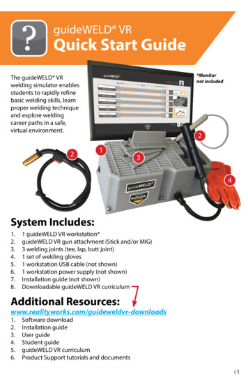
guideWELD VRQuick Start Guide*Monitornot includedThe guideWELD VRwelding simulator enablesstudents to rapidly refinebasic welding skills, learnproper welding techniqueand explore weldingcareer paths in a safe,virtual environment.22134System Includes:1.2.3.4.5.6.7.8.1 guideWELD VR workstation*guideWELD VR gun attachment (Stick and/or MIG)3 welding joints (tee, lap, butt joint)1 set of welding gloves1 workstation USB cable (not shown)1 workstation power supply (not shown)Installation guide (not shown)Downloadable guideWELD VR curriculumAdditional ds1.2.3.4.5.6.Software downloadInstallation guideUser guideStudent guideguideWELD VR curriculumProduct Support tutorials and documents(1
WORKSTATION SETUPHardware Setup1. Plug the USB cord into the guideWELD VR workstation(Fig. 2A) and into a compatible computer2A2. Plug the power cord into the guideWELD VR workstation(Fig. 2B) and an electrical wall outlet2B3. Choose the welding gun (Stick and/or MIG)4. Line up the connection holes in the workstation with theconnection pins on the connector at the end of thewelding gun hose (Fig. 2C)2CNOTE: There is an alignment dot on the welding gunconnector and workstation connector to assist withproper alignmentSecurely fasten the gun hose by twisting the tighteninglock on the gun hose connector (Fig. 2D)5. Turn the workstation switch from “OFF” (Fig. 2E)to “ON” (Fig. 2F)2D2ENOTE: The first time the guideWELD VR workstationis connected to a computer, these steps must becompleted in this exact order for the computer torecognize the hardware2F2)
SOFTWARE INSTALLATION AND SETUPNOTICE! Follow each step below to launch and begin using theguideWELD VR software. All steps must be completed to begin welding.SoftwareDownload and install the guideWELD VR software wnloadsReference the Installation Guide for additional instructions.NOTE: Administration credentials may be required1. Launch the guideWELD VR software by clicking thecomputer desktop2. A Configuration screen will be displayed (Fig. 3A)3. The following options and selections will3Aappear on the screen: LANGUAGE: Default is English (US) RESOLUTION: Defaults to your computer settings FULLSCREEN: “OFF” mode is for a windowedview of the software, “ON” mode is for a fullyexpanded screen GRAPHICS: Reduce or increase the amount ofgraphic usage that the software will need4. Selectto go to the Login ScreenAdmin Accountimage on the3B1. Enter the default admin usernameand the default password (Fig. 3B)Username: adminPassword: admin2. A change PASSWORD SCREEN will appear (Fig. 3C)3. Create a new passwordNOTE: The new password must be 6-14 lettersand/or numbers (example: 123abc)3CSOFTWARE INSTALLATION AND SETUP (ADMIN ACCOUNT) continued on next page (3
SOFTWARE INSTALLATION AND SETUP (continued)Add an Instructor Account1. On the Admin Screen, enter Instructor’s first and last name, click2. A username is created using the first two letters of the first name and up to eightletters of the last name (example: Tom Washington is towashingt)Note: The default password is “PASSWORD” and the Instructor will be prompted tocreate a new password at first login3. Create additional Instructor accounts as needed4. Clickto exit AdminInstructor AccountCreating Classes1. Login with Instructor Account informationNote: The instructor will be prompted to create a new password at first login2. On the Class Selection screen, click the Add Class button (in the name of the classNote: the class name cannot be more than 12 characters3. Click the Save button () and type)Creating Student Accounts1. Click on the Edit Student icon () to create Student Accounts2. Enter student first name and last name – a username will be createdNote: The default password is “PASSWORD” and the student will be prompted to createa new password at first login3. Click Add Student () and create additional Student Accounts as neededCreating Class Assignments1. On the Class Selection screen, click on the Edit Class icon () to create a classassignment list Default Class Assignments (pre-assigned Welding Procedure Sheets):27 MIG and 27 Stick2. View the Available Assignments on the left side of the screen and click the “ ” iconto move assignments to the Class Assignment list on the right side of the screen3. The assignment is now assigned (and visible) to the class and Student Accounts4. Click the “-” icon to remove the assignment from the Class Assignment list4)
REVIEW DATA COLLECTIONClass ReportsOn the Class Selection screen, click on the Class Report icon (the following:) to review1. ASSIGNMENT: WPS specification assigned to a class2. ASSIGNMENT DETAIL: Attributes of the assignment3. MATERIAL SAVINGS: Monetary savings of utilizing guideWELD VR versus actualwelding materials4. CLASS AVERAGE: Test grades from each of the students in the class for thespecific assignment5. TOTAL CLASS AVERAGE: Class average of all tests completed for a specific class6. TOTAL MATERIAL SAVINGS: Total monetary savings of utilizing guideWELD VRversus actual welding materials for the class on all assignmentsStudent ReportsSelect a Class to view student reports1. Click on the Student Report icon to see the result for each student (Fig. 5A)Note: Class and Student report icons are grayed out until at least one weldhas been executed and saved2. Click on the Student’s name along the left hand side of the screen3. View the student’s progress on each assignment5A(5
USER/STUDENT DIRECTIONSStudent AccountPrepare to Weld1.2.3.4.Connect the guideWELD VR workstation to a computer with VR software installedSelect the welding gun (MIG or Stick)With the workstation powered off, attach the selected welding gunPower on the workstation and launch software and login with Student Accountinformation. Note: The default password is “PASSWORD”5. Determine the coupon (tee, lap or butt joint) to be used for the assignment andplace chosen coupon on the workstation6. In the main Student Screen, choose an assignment and click on the Practice button.Chosen assignment should match welding gun and couponTest vs. Practice ModePractice mode allows use of the technique guides, while Test mode does not. Testmode is available only after a student achieves a grade of 50% or higher while inPractice mode.Optional corrective technique guides include:Note: An equal sign will display when performing proper technique1. WORK ANGLE: TOP LEFT CORNER – if an up arrow shows, move the buttof the welding gun up. If a down arrow shows, move the butt of the gundown. The nozzle or tip of the electrode should remain on path (Fig. 6A)2. TRAVEL ANGLE: TOP RIGHT CORNER – if a right arrow shows, tilt thegun to the right. If a left arrow shows, tilt the gun to the left. (Fig. 6B)3. SPEED: IN FRONT OF WELDING GUN AND COUPON – displays thetravel speed and gives a plus sign when speed should increase anda minus sign when speed should decrease (Fig. 6C)4. NOZZLE TO PLATE DISTANCE: ON WELDING NOZZLE/ELECTRODE –displays correct distance from the work coupon and the gun nozzle.If positioning is correct, a green circle will appear, while a red arrowwill appear when out of position (Fig. 6D)5. STRAIGHTNESS: ABOVE AND BELOW THE METAL – the dotted lineshows right location on the work coupon (Fig. 6E)6A6B6C6D6ETacking the Coupon (prior to each weld)Tacking the coupon needs to be complete on the main welding screen1. Ensure the message TACK LEFT SIDE OF PLATE AS SHOWN is displayed2. Bring the physical welding gun into the same position as the virtual welding gunshown on the screen. The nozzle of the MIG gun or tip of the electrode of the Stickgun must be centered on the far left edge touching the coupon, with the samework angle as the virtual welding gun (Fig. 7A)6)
3.4.5.6.7.NOTE: For a Tee and Lap Joint, position the gun at a 45-degree angle and the gunhandle parallel to the edge of the coupon. For a Butt Joint, position the gun at a90-degree angle and the gun handle parallel to the edge of the coupon.Pull the trigger (MIG) or press the orange button (Stick) and releaseOnce completed, the TACK RIGHT SIDE OF PLATE AS SHOWN message isdisplayed in the simulatorBring the physical welding gun to the right side of the coupon and into the sameposition as the virtual welding gun shown on the screen. (Fig. 7B)Pull the trigger (MIG) or press the orange button (Stick) and releaseBegin weldTacking coupon with a STICK gunTacking coupon with a MIG gun7A7BExecute a WeldMIG welding1. Position the welding gun near the coupon as directed by the assignment2. Pull the trigger to begin welding3. Move the welding gun in the assigned direction of travel4. Release the trigger at the end of the coupon5. Click the Save button () in the lower right cornerStick welding1. Allow the electrode to extend until it stops2. Position the tip of the electrode just outside the coupon starting point as directedby the assignment3. Move in the assigned direction of travel to begin weldingNote: If done incorrectly you may stick the electrode to the coupon within thesimulation and will be prompted to restart/unstick4. To end the weld, back the electrode away from the coupon5. Click the Save button ()USER DIRECTIONS continued on next page (7
USER DIRECTIONS (continued)Reviewing Assignment ResultsA results screen isdisplayed aftersaving thecompleted weld(Fig. 8A) If the performance(indicated by theorange line) isinside the grayshaded area,the weld wasdone correctly. If the performance(indicated by theorange line) isoutside the gray shaded area, more practice is needed.8AAdditional Help and InformationVisit: www.realityworks.com/guideweldvr-downloads1. Complete user guide2. guideWELD VR curriculum3. Product Support tutorials and documentsOnline Product SupportWe’re here to help! Our online Product Support features video tutorials, downloadabledocuments, frequently asked questions and product notices, all of which make it easyfor you to get support for products, software and more, day or night. Find our onlineproduct support area here: www.realityworks.com/support/Online StoreSupplies, accessories, select simulators, curriculum and more areavailable for purchase from our online store 24 hours a day!Find our online store here: http://store.realityworks.comwww.realityworks.com 800.830.1416 2018 Realityworks, Inc. All rights reserved.1033040-11 7/20188)
Stick welding 1. Allow the electrode to extend until it stops 2. Position the tip of the electrode just outside the coupon starting point as directed by the assignment 3. Move in the assigned direction of travel to begin welding Note: If done incorrectly you may stick