Transcription
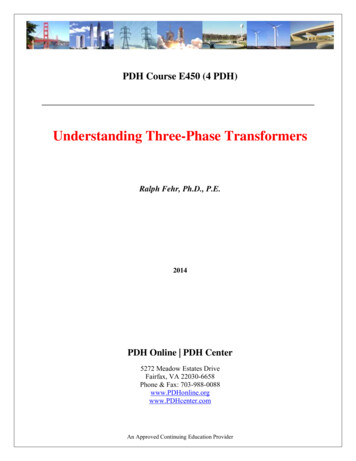
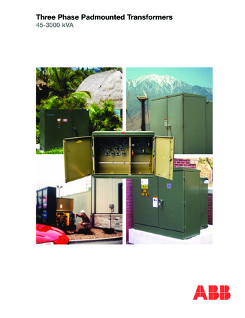
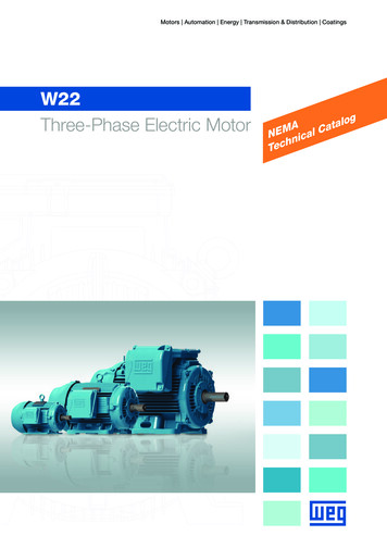
THREE-P HASE TRANSFORMERSTransformers used in three-phase systems may consist of a bank ofthree single-phase transformers or a single three-phase transformer whichis wound on a common magnetic core. A three-phase transformer woundon a common core offers advantages over a bank of single-phasetransformers. A three-phase transformer wound on a common core islighter, smaller and cheaper than the bank of three single-phasetransformers. The common core three-phase transformer also requiresmuch less external wiring than the bank of single-phase transformers andcan typically achieve a higher efficiency.The bank of three single-phase transformers does offer the advantageof flexibility. In the case of an unbalanced load, one or more transformerin the bank can be replaced by a larger or smaller kVA-rated transformer.In terms of maintenance, a malfunctioning transformer in the bank oftransformers can be easily replaced while the entire common core threephase transformer would require replacement.The bank of single-phase transformers or the common core threephase transformer can be connected in one of four combinations relative tothe primary and secondary connections.Wye-Delta:Commonly used in a step-down transformer, wyeconnection on the HV side reduces insulation costs,the neutral point on the HV side can be grounded,stable with respect to unbalanced loads.Delta-Wye:Commonly used in a step-up transformer for thesame reasons as above.Delta-Delta:Offers the advantage that one of the transformerscan be removed while the remaining twotransformers can deliver three-phase power at 58%of the original bank.Wye-Wye:Rarely used, problems with unbalanced loads.
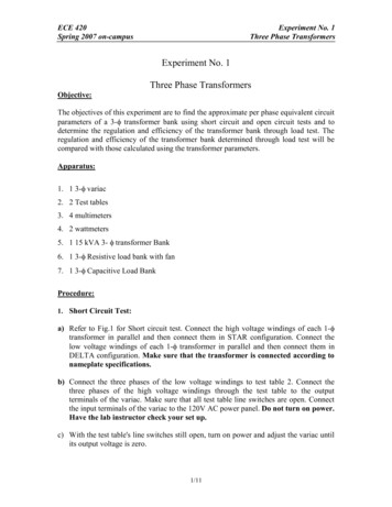
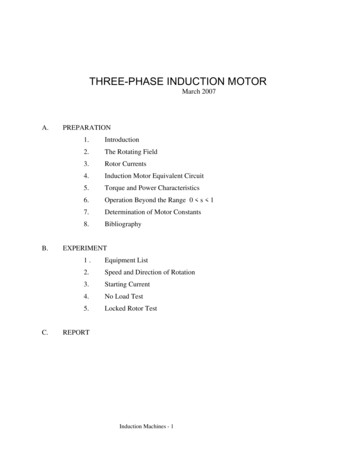
Wye-Delta ConnectionDelta-Wye Connection
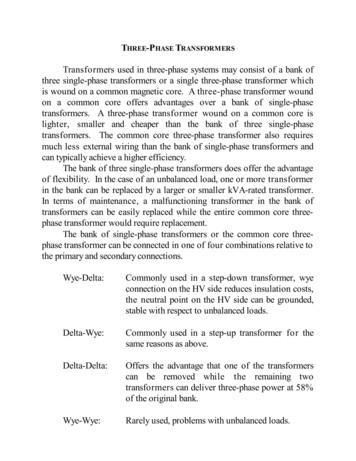
Delta-Delta ConnectionWye-Wye Connection
Note that the voltage across a wye-connected primary or secondarywinding is the line-to-neutral voltage while the voltage across a deltaconnected primary or secondary winding is the line-to-line voltage. Themagnitude of the complex three-phase power into or out of a three-phasetransformer in a balanced system may be written aswhere Vw is the magnitude of the voltage across each winding and Iw is themagnitude of the current through each winding. In the wye-configuration,the winding voltage is the line-to-neutral voltage (VLN) while the windingcurrent is the line current (IL). In the delta-configuration, the windingvoltage is the line-to-line voltage (VLL) while the winding current is thedelta current (I)). Thus, for a wye-connected winding, the magnitude of thecomplex power isThe magnitude of the complex power for the delta-connected winding isso that the equation for the complex power for either transformer windingconnection is the same given the line-to-line voltage and the line current.
PER-PHASE ANALYSIS OF THREE-PHASE TRANSFORMERSAssuming the three transformers in the three-phase transformer areidentical and the sources and loads in the three-phase problem are balanced,circuits involving a the three-phase transformer can be analyzed on a perphase basis as illustrated in our study of three-phase circuits. Aspreviously discussed, the easiest three-phase topology to analyze is thewye-wye connection. Thus, given any other configuration for the threephase transformer other than wye-wye, one should transform the circuitinto wye-wye form.The equivalent turns ratio for the transformed wye-wye per-phaseequivalent circuit for the transformer is the ratio of the primary line-to-linevoltage to the secondary line-to-line voltage for the original configuration.The concept of the equivalent turns ratio can be illustrated by an exampletransformation of a transformer configuration.The wye-delta and delta-wye configurations of three-phasetransformers result in 30o phase shifts between the primary and secondaryline-to-line voltages. The industry standard is such that the lower voltagesin these configurations should lag the higher voltages by 30o. The wye-wyeor delta-delta configurations produce line-to-line voltages in the primaryand secondary that are in phase.
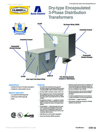
ExampleTransform a wye-delta three-phase transformer into the wye-wyeconfiguration and determine the equivalent turns ratio aN of the resultingwye-wye transformer. Draw the per-phase equivalent circuit for theresulting wye-wye transformer.The line-to-neutral voltages across the windings of the equivalent wyeconnected secondary are found by dividing the line-to-line voltages across3.the windings of the of the delta-connected secondary by %&
Comparing the voltages and currents of the primary and secondarywindings, we see the that the equivalent turns ratio of the wye-wyeconfiguration isThe equivalent wye-wye model for the wye-delta connected three-phasetransformer isIn a similar fashion, if we consider the transformation of the the deltawye and delta-delta configurations to the wye-wye configurations, we findequivalent turns ratios of
Example (Per-phase equivalent circuit / three-phase transformer)Three single-phase 50 kVA, 2300/230 V 60 Hz transformers areconnected to form a three-phase 4000/230 V transformer bank (thesevoltages are line to line) which supplies a 120 kVA, 230 V, three-phaseload with a power factor of 0.85 lagging. The equivalent impedance foreach transformer referred to the LV winding is (0.012 j 0.016) S.(a.) Determine the transformer configuration required and draw theper-phase equivalent circuit.(b.) Determine the transformer winding currents.(c.) Determine the primary voltage required to produce the ratedoutput.(d.) Determine the voltage regulation.(a.) Individual transformers:Primary winding rated voltage V1,rated 2300 VSecondary winding rated voltage V2,rated 230 VTurns ratio a N1/N2 V1,rated /V2,rated 2300/230 103N transformer:3Primary line to line voltage V1,LL 4000 V . 2300 %&Secondary line to line voltage V2,LL 230 VY-Y equivalent turns ratio aN V1,LL/V2,LL 4000/230 17.39The required transformer connection is Wye-Delta.
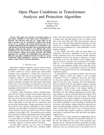
The given equivalent impedance for each transformer is referred tothe LV winding (secondary). This impedance referred to the HVinput winding isNote that the turns ratio of the individual transformer is used toreflect the impedance between the primary and the secondary. Theresulting wye-wye per-phase equivalent circuit is shown below.(b.) The line current delivered to the three-phase load can be found fromthe complex power equation:The actual current in the delta-connected secondary winding of thistransformer isThe corresponding current in the wye-connected primary is
(c.) To determine the line-to-line voltage on the primary required toproduce a secondary line-to-line voltage of 230 V, we must analyzethe per-phase equivalent circuit. In the per-phase equivalent circuit,the current I2 is the secondary line current (magnitude 301.23 A)while the voltage V2 is the secondary line-to-neutral voltage(magnitude 230/ %&3 132.79 V). The power factor of the loadgives the phase angle difference between V2 and I2.Using the secondary line-to-neutral voltage as our reference givesThe secondary values can be reflected back to the primary accordingto the modified turns ratio aN.
The resulting primary voltage V1 (line-to-neutral) isThe magnitude of the primary line-to-line voltage is(d.) The voltage regulation of this transformer is given by
connected to form a three-phase 4000/230 V transformer bank (these voltages are line to line) which supplies a 120 kVA, 230 V, three-phase load with a power factor of 0.85 lagging. The equivalent impedance for each transformer referred to the LV winding is (0.012 j 0.016) S. (a.) Determine the