Transcription
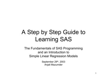
WSEAS TRANSACTIONS on POWER SYSTEMSAntonio Testa, Salvatore De Caro, Tommaso ScimoneSizing of Step-Up Transformers for PV Plantsthrough a Probabilistic ApproachANTONIO TESTA, SALVATORE DE CARO, TOMMASO SCIMONEDepartment Electronic Engineering, Industrial Chemistry and EngineeringUniversity of MessinaContrada Di Dio – 98166 Messina (ME)ITALYatesta@unime.it, sdecaro@unime.it, tscimone@unime.itAbstract: - Step-up transformers are used to connect large PV plants to the utility network, their sizing beingoften accomplished only taking into account the PV plant peak power. However, a largely unpredictable powerinjection on the main grid is obtained if a too large rated power is selected, leading to grid instabilities. Thismay result in plant shutdowns, while requiring a remarkable reserve power to be provided by conventionalgeneration systems. On the other hand, a too small transformer lead to the creation of a bottleneck, preventingan optimal exploitation of the solar energy. This situation becomes more complex if the introduction of anenergy storage system is considered. In the present paper a design technique is proposed to optimally select thestep-up transformer, either on conventional PV plants, either on PV plants with energy storage. It is based onthe evaluation of initial and operating costs. Moreover, the effects of induced network instabilities are alsoconsidered. Taking into account full life costs optimal solutions have been detected according to the networkpower control capabilities for a 2 MW PV plant.Key-Words: - Photovoltaic power systems, Power generation, Transformers, Energy storage, Power Plants,Systems Efficiency.concern, but also the influence of the transformersize either on the amount of energy delivered to themain utility, either on the stability of the network.In fact, while selecting a transformer rated powerclose to the PV plant peak power makestheoretically possible to fully transfer the capturedsolar energy to the utility network, such a designcriterion will in practice lead to oversize both thetransformer, the inverter and the power line.Moreover, a too large transformer would operatefor long times at a reduced efficiency, whilegenerating a largely unpredictable power injectionon the main grid [6-9]. The last may lead to gridinstabilities, causing frequent plant shutdowns, andrequiring a remarkable reserve power to be providedby conventional generators. On the other hand, a toosmall step-up transformer would constitute abottleneck, preventing an optimal exploitation of thesolar energy.A PV energy plant is quite unreliable, because ofthe stochastic nature of the solar irradiation [10-14].To allow such a plant to match the standardrequirements for grid stability some forms of energystorage can be introduced. The idea of locally1 IntroductionPhotovoltaic power plants (PV) are today rapidlyspreading all over the countries, as a result ofspecific governmental policies, powered by strongclimate concerns [1-4]. As shown in Fig. 1, in atraditional PV plant a large number of PV modulesare series connected in long strings and a singlecentralized inverter provides the voltage inversion.Step-up transformers are required to boost the480 690 V inverters output voltage to the 13.8 46kV of the medium voltage utility network [4]. Thestring architecture is however burdened by a ures have been developed where PVmodules are arranged in strings, or even substrings,each one connected to the step-up transformerthrough a dedicated inverter, or a dedicated DC/DCconverter and a centralized inverter.Conventional distribution transformers arewidely used, either singly or paralleled, to connectthe inverter to the main power line. The step-uptransformer is a key element of a PV system, as itprocesses the whole generated energy. Moreover,not only the efficiency and the cost are of primaryE-ISSN: 2224-350X114Issue 3, Volume 8, July 2013
WSEAS TRANSACTIONS on POWER SYSTEMSAntonio Testa, Salvatore De Caro, Tommaso Scimonestoring energy to avoid network instabilities and toreduce the size and cost of power lines serving PVplants or wind turbines is not new [15, 16]. Severaltraditional energy storage technologies have beenconsidered to accomplish this task. Among them:pumped hydroelectric storage, batteries andcompressed air energy storage. Moreover, in the lastyears, some advanced technologies have been alsodeveloped including: flywheels, superconductingmagnets, fuel cells with electrolyzers and redoxflow cells. The last technology, in particular, todayappears very promising, requiring inexpensiveinfrastructures if compared with pumpedhydroelectric and compressed air energy storage,while making possible to store energy on longerterms if compared with flywheels andsuperconducting magnets. Finally, redox flowbatteries are less expensive and more reliable thanfuel cells and conventional batteries.The selection of the rated power of the step-uptransformer becomes more complex whenconsidering a PV plant with energy storagecapabilities, as an optimal solution must be detectedtaking also into account the features and the cost ofthe Energy Storage System (ESS) and their effectson the cost and efficiency of the whole system.the system, energy losses due to transformerefficiency, energy storage system efficiency andpossible plant disconnections due to grid instability.The aim of this work is to develop a generalmethodology to accomplish an optimal sizing ofstep-up transformers for PV plants, either directlydelivering power to the utility network, eitherequipped with energy storage systems [17,18].2 Step-uptransformersconventional PV plantsforThe cost of the step-up transformer for a PV plantcan be evaluated as a composition of fourcontributions, namely: initial cost cost of the energy wasted due to transformeroverloads cost of energy wasted due to transformerefficiency cost of energy wasted due grid instability2.1 Initial costEven conventional distribution transformers arewidely used as step-up transformers for PV plants,their customer price can be hardly estimated. In fact,they often are custom built units with unlistedprices. Only considering commercial off the shelftransformers and neglecting taxes and marketingmarkups, the cost curve of Fig. 2 can be considered,as function of the rated power. Main contributionsto the final cost are given from manufacturer sellingprice, shipping and installation costs. Moreover, asthe size and the cost of the inverter serving the plantare also closely related to the transformer ratedpower, a specific cost function, shown in Fig. 2, isassumed.Fig. 1.String arranged (up) and decentralized (down)PV arrays with centralized inverter.In general, the selection of the step-uptransformer in a PV plant is a quite complex task asseveral variables depending on the transformer ratedpower must be taken into account as: initial cost ofE-ISSN: 2224-350XFig. 2. Step-up transformer and inverter initial costs115Issue 3, Volume 8, July 2013
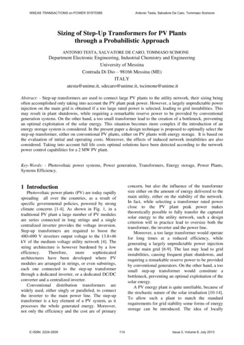
WSEAS TRANSACTIONS on POWER SYSTEMS2.2 EnergyoverloadslossesduetoAntonio Testa, Salvatore De Caro, Tommaso Scimonefollowed based on the LPPP (Loss of ProducedPower Probability) index. Such an approach derivesfrom the well-known LPSP (Lost of Power SupplyProbability) technique used on PV plants operatingin island mode [19-24].To accomplish the LPPP analysis over a given timewindow T the last is divided into N intervals, eachone Δt T/N long. Typically, these intervals aretaken to be of one hour duration. It is assumed that:if Pi(k), the average input power during the k-thinterval is greater than 110% the transformer ratedpower Pn, the excess power is lost, as it cannot beprocessed. For each k-th time interval, the LPP(Loss of Produced Power) parameter is computedaccording to Fig. 4.The value of the LPPP index is then determined asfollows:transformerStarting from an average daily solar irradiationprofile, as that of Fig. 3, the transformer input powerPi can be computed as:Pi (t ) Irr (t ) S PV(1)TEi Pi (t )dt0(2)where: S is the total net area of PV modules, Irr(t) isthe solar irradiation at time t and ηPV is the overallefficiency of PV panels and the power converters.NLPPP LPP(k )k 1N(3) Pi(k ) tk 1The LPPP index is zero when the maximum amountof the solar energy captured over a day by PVmodules is effectively delivered to the utility grid.The lost energy and the associated cost areevaluated as follows:Fig 3.Average daily solar irradiation in southernEurope.NEW Pi (k ) t LPPP(4)CEW EW Ce(5)k 1Depending on to the transformer rated power, someof the energy captured by PV modules cannot bedelivered to the utility network.Being Ce the energy selling price per kWh.2.3 EnergyefficiencylossesduetotransformerThe power wasted due to no load and copper lossesduring the k-th interval can be computed through thefollowing equation, assuming constant theamplitude of the inverter output voltage:Pd (k ) Pv Pc 2Pi (k)Pn2(6)where: Pv represents the no-load losses and Pc therated copper losses.The total energy wasted due to transformer powerlosses and the associated cost are then obtained as:NFig 4.Flowchart of the LPP algorithmED Pd (k ) t(7)CED ED Ce(8)k 1In order to evaluate the energy loss due totransformer overloads a probabilistic approach isE-ISSN: 2224-350X116Issue 3, Volume 8, July 2013
WSEAS TRANSACTIONS on POWER SYSTEMSAntonio Testa, Salvatore De Caro, Tommaso Scimonerange defined by the local grid code, the invertermust be disconnected from the grid. Therefore, alarge PV plant without energy storage is fairlysubjected to frequent shutdowns to maintain thenetwork stability. This causes additional energylosses. Energy losses caused by network instabilitiescan hardly be predicted in a general way. However,it is plain that they depend from PV plant peakpower and the utility network stability margins [26]Assuming that an average shutdown consists of afour hours long full plant disconnection, centered onthe peak of the solar irradiation, the energy lost dueto grid instabilities and the associated cost can becomputed as follows:2.4 Energy losses due to grid instabilityElost kPpk N(9)CElost Elost Ce(10)being Ppk the peak output power of the plant and Nthe total time in hours per year in which the systemis disconnected from the utility grid for stabilityreasons.2.5 Transformer size selectionConsidering a 2MW peak power PV plant, thetransformers whose main data are summarized inTable I have been selected for comparison. Tosimplify the comparison only single units areconsidered, working at unity power factor [25].However, the proposed approach can be easilygeneralized to transformer banks working at anarbitrary power factor. Estimating in 25 years thelifetime of the PV plant, total energy losses havebeen first computed as shown in Fig. 5.TABLE I –Step-up Transformers main dataRated power [kVA]Pv [kW]Pc 00213.0020002.416.08Fig 5. ED and EW over 25 years vs. rated power.Energy losses over 25 years due to grid stability havebeen also evaluated as shown in Fig. 6 as function of N.The utility grid is forced to work around the point ofbalance between the power demand and thegenerated power. A suitable control system, in fact,manages the reserve conventional generation powerto maintain the stability of the entire network. Thesolar irradiation is intermittent; moreover it oftenunpredictably varies according to the weatherconditions. Therefore, the utility control system seesthe power stream generated by a PV plant as adisturbance. The control system is able tocompensate such a disturbance only until thedelivered intermittent power represents a smallshare of the total power of conventional generatorsconnected to the grid. Such a share differs fromcountry to country, but it ranges between 5 and25%. The injections on the grid of different powerplants often lead to an huge instability, varyingfrequency and amplitude of the voltage of the grid.If these variations exceed the standard operativeE-ISSN: 2224-350XFig 6.Elost over 25 years vs. expected hours ofdisconnection per year.The cost of energy losses over 25 years has been thencalculated and added to the initial cost of thetransformer and the inverter. Taking also into account117Issue 3, Volume 8, July 2013
WSEAS TRANSACTIONS on POWER SYSTEMSAntonio Testa, Salvatore De Caro, Tommaso Scimonea 3% annual rate of interest, the life costs of thetransformer and the inverter have been computed.Estimated life costs are then subtracted to the totalprice of the energy delivered to the main utility in 25years. As shown in Fig. 7 the most advantageoustransformer is that rated at 1 MVA.3.1 Initial costIn this case the cost of the energy storage systemmust be added to the cost of the transformer and ofthe inverter. A cost curve for large VRB ESS isshown in Fig. 8.Fig. 8.VRB Energy Storage System initial cost.3.2 Energy lossesoverloadsFig 7. Total life cost vs. expected hours of per year.The LPP is computed for each k-th intervalaccording to the flow-chart reported in Appendix A.If Pi(k) is larger than 110% the transformer ratedpower, the excess energy can be stored into theVRB ESS, taking into account conversion andcharge efficiencies. However, if the state of chargeof the ESS is nearly 100% the excess energy is lost.Moreover, if the excess power outreaches the VRBESS maximum power PESSMAX the surplus energy islost. If Pi(k) is lower than the transformer ratedpower, some energy is drawn from the VRB ESS tokeep the transformer at the maximum efficiencyworking point. Moreover, if Pi(k) is greater than Pottthe input power corresponding to the maximumefficiency working point, all the power is deliveredto the utility network. If not, some power isprovided from the energy storage system.The LPPP index, the lost energy and the associatedcost can be evaluated according respectively to eqs.(3), (4) and (5).3 Transformer for PV plants withenergy storageVanadium Redox Batteries (VRB) have beenselected among available energy storage systemsto equip the considered PV plant. In a VRB-ESSthe energy is transferred to the electrolyte, ratherthan being stored into the electrodes as inconventional batteries. As a result, a VRB-ESScan be easily charged, discharged and rechargedover 10,000 times (from 20% to 80% of the stateof charge) with a high efficiency (65% 75%),while ensuring a power availability greater than98%. Moreover, a VRB-ESS is easily scalableeither in power, either in storage capability,respectively acting on the number of flow cellsand the size of the electrolyte tanks.If compared with lead-acid batteries, VRB showsomeadvantageousfeatures,suchas:compactness, shorter charge times, an increaseddischarge depth, longer lifetimes and lowermaintenance costs.Moreover, VRB systems are suitable to performeither short time operations, such as compensationof load peaks and voltage drops, either medium orlong time operations, as required by energymanagement strategies.E-ISSN: 2224-350Xdue to transformer3.3 Energy losses due to transformerefficiency and grid instabilityThe power wasted due transformer losses duringthe k-th interval can be computed through eq. (6),while associated lost energy and cost through eqs.(7) and (8) respectively.A PV plant equipped with an energy storagesystem is able to modulate the power delivered tothe grid, leading to fewer shutdowns if compared118Issue 3, Volume 8, July 2013
WSEAS TRANSACTIONS on POWER SYSTEMSAntonio Testa, Salvatore De Caro, Tommaso Scimonewith a PV plant featuring the same peak powerbut no energy storage. In order to compare PVplants with and without energy storage anequivalent total amount of hours per year in whichthe system is disconnected from the utility grid isdefined as:NI PNPpkof the energy storage system is close to the initialvalue. The first approach lead to the minimizationof the transformer rated power.The second approach lead to the maximization ofthe average system efficiency.The third approach has been considered as anattempt to reduce the cost of the VRB ESS, onlyslightly lowering the average system efficiency.(11)being ΔP the power variability, defined as thedifference between P pk and the minimum value ofthe power delivered to the utility grid over a day(zero if no energy storage is provided). Accordingto eq 11 the total length of grid disconnections isquite conservatively considered proportional tothe variability of the power generated by the PVplant. Therefore, without energy storage ΔP isequal to P pk, giving N’ N. At the contrary, if asuitable energy storage system holds constant thepower generated over a day, N’ becomes zero. Infact, if the generated power is constant and fullypredictable, no interference to the grid stabilitymay occur. Under the above mentionedhypotheses, the energy lost by a PV plant due tosystem instabilities, can be estimated as:Elost Ppk N I PN(12)a)Different hypotheses can be easily alsoconsidered, as partial disconnections, or averageplant disconnections featuring different lengths.Additional costs due to possible systemshutdowns can be computed through eq. 10.b)3.3 Transformer size selectionThe 2 MW PV plant previously described is hereconsidered including a VRB-ESS featuring a 75%round trip efficiency. Three different designapproaches have been considered, namely:1.2.3.A VRB ESS featuring the minimum size toensure LPPP 0 (maximum solar energydelivered to the utility grid), while holdingthe transformer working at the rated power.A VRB ESS able to ensure LPPP 0, whileholding the transformer working at themaximum efficiency during the discharge ofthe energy storage system.A VRB ESS able to ensure LPPP 0, whileholding the transformer working at 99% ofthe maximum efficiency during the dischargeof the energy storage system.c)Fig 9. LPPP index for a) 250, b) 400, and c) 600kVA transformer.A VRB ESS can be independently sized onstorage capacity and power. Therefore the LPPPindex analysis has been exploited to find the mostadvantageous combination among: transformerrated power, VRB ESS energy storage capabilityand VRB ESS maximum power, for the threeapproaches.Considering the transformers whose data areshown in Table I, optimal solutions for the threeconsidered approaches are reported in Table III.In Fig. 9 the LPPP index for different values ofIn any case the energy balance over a day must benearly zero, to ensure that the final state of chargeE-ISSN: 2224-350X119Issue 3, Volume 8, July 2013
WSEAS TRANSACTIONS on POWER SYSTEMSAntonio Testa, Salvatore De Caro, Tommaso ScimoneThe life cost of the three selected solutions hasbeen computed also considering the initial cost ofthe energy storage system. Life costs have beenthen subtracted to the proceeds of the sale ofenergy over 25 years. Obtained results are shownin Fig. 13 and compared with the best solutionobtained without energy storage.As it is possible to observe for very stable utilitygrids the most advantageous solution is indeedthat without energy storage.However, decreasing the grid stability margins,PV plants with ESS perform better. Specifically,over an expected global duration of shutdownslarger than 140 hours per year, the PV plant witha 600 kVA transformer and a 1800 kWh VRBESS is progressively more advantageous.Over 850 hours per year of expected plantshutdown, the most advantageous solution is thatwith a 400 kVA transformer and a 3600 kWhVRB-ESS.VRB ESS energy storage capability andmaximum power is shown for the three selectedsolutions.TABLE II – PV plant with energy storage : selectedsolutionsDesignTransformer VRB ESS VRB 01800325Results of some simulations dealing with thebehaviour of the three selected solution over a dayare shown in Figs. 10 and 11. Specifically, the VRBESS state of charge and the transformer efficiencyover an average day, according to the three solutionsare shown.Fig 12. Elost over 25 years vs. expected hours ofdisconnection per year.Fig 10.VRB ESS state of charge over a day.Fig 11.Transformer efficiency over a day.As in systems without energy storage, energylosses over 25 years due to grid stability have beencomputed, as shown in Fig. 12 for the threesolutions and for different values of N.E-ISSN: 2224-350XFig 13. Total life cost vs. expected hours ofdisconnection per year.120Issue 3, Volume 8, July 2013
WSEAS TRANSACTIONS on POWER SYSTEMSAntonio Testa, Salvatore De Caro, Tommaso Scimonenumber of plant disconnections due to gridinstability.The proposed approach is based on theevaluation of a probabilistic index the LPPP,to estimate the costs of energy losses relatedto the size of the transformer and the powerand the storage capability of the ESS.Moreover, energy losses related to gridinstabilities are also considered. Taking intoaccount full life costs optimal solutions canbe detected according to the grid powercontrol capabilities.4 ConclusionsA general methodology to accomplish anoptimal selection of the rated power of stepup transformers in PV plants with or withoutenergy storage systems has been presented.A correct selection of size of the step-uptransformer in a PV plant involves a deepanalysis of the whole system, as severalvariables are related to the transformer ratedpower as: initial cost of the system, energylosses due to transformer efficiency, energystorage system efficiency and the expectedAPPENDIX AFlowchart of the LPP algorithm.E-ISSN: 2224-350X121Issue 3, Volume 8, July 2013
WSEAS TRANSACTIONS on POWER SYSTEMSAntonio Testa, Salvatore De Caro, Tommaso ScimoneReferences:[1] ds; Final Rule” U.S. Department ofEnergy.[2] T. Senjyu, T. Nakaji, K. Uezato, and T.Funabashi, “A hybrid power system usingalternative energy facilities in isolatedisland,” IEEE Trans. Energy Convers., vol.20, no. 2, pp. 406–414, Jun. 2005.[3] Zahran, M. “Smart grid technology, vision,managementandcontrol”WSEASTransactions on Systems Volume 12, Issue 1,January 2013[4] Zhao, J., Yang, X., Jiang, J. “Implementationand study of grid-connected control fordistributed generation system“ WSEASTransactions on Systems Volume 9, Issue 5,May 2010, Pages 570-579.[5] “Power electronics and control of renewableenergy systems” by F. Iov, M. Ciobotaru, D.Sera, R. Teodorescu, and F. Blaabjerg,Article published in Proceedings of PEDS,2007, keynote paper, pp. P-6-P-28.[6] Electrical supply tolerances and electricalappliance safety, standards & w.dti.gov.uk/files/file11548.pdf.[7] B. H. Chowdhury, “Effect of central stationphotovoltaic plan on power system security”,Photovoltaic Specialist Conference, 1990,Conference Record of Twenty-First IEEE,vol. 2, 21-25 May 1990, pp. 831-835.[8] Reis, C.; Barbosa, F.P.M “ Line indices forvoltage stability assessment” PowerTech,2009 IEEE Bucharest, pp. 1 – 6.[9] Suganyadevia,M.V.;Babulal,C.K.;“Estimating of load ability margin of a powersystem by comparing Voltage StabilityIndices “International Conference on Control,Automation, Communication and EnergyConservation, 2009. INCACEC 2009, pp. 1 –4.[10] J.Nahman, M.Graovac, “Load Modelling forgenerating capacity reliability evaluationusing the frequency and duration method”,proceedings IEE, 139 Part C, 1992, pp.529535[11] E. C. Kern , E. M. Gulachensky, G. A. Kern,“Cloud Effects on Distributed PhotovoltaicGeneration: Slow Transients at the Gardner,Massachusetts Photovoltaic Experiment”,IEEE Transaction on Energy Conversion,vol. 4, No. 2, June 1989, pp. 184-190.E-ISSN: 2224-350X[12] Chen, S., Li, P., Brady, D., Lehman, B. Theimpact of irradiance time behaviors oninverter sizing and design (2010) Proc IEEE12th Workshop Control Modeling PowerElectron, pp. 1-5.[13] L. Wang, Y. H. Lin, “Random fluctuations ondynamic stability of a grid connectedphotovoltaic array”, Power EngineeringSociety Winter Meeting, 2001, IEEE, vol. 3,28 Jan – 1 Feb 2001, pp.985-989.[14] Shi, J., Lee, W.-J., Liu, Y., Yang, Y., Wang,P. “Forecasting power output of photovoltaicsystems based on weather classification andsupport vector machines” (2012) IEEETransactions on Industry Applications[15] Edrington, C.S., Balathandayuthapani, S.,Cao, J. “Analysis of integrated storage andgrid interfaced photovoltaic system via nineswitch three-level inverter” (2010) IECONProceedings(IndustrialElectronicsConference), art. no. 5675035, pp. 32583262.[16] Irfan Guney, Nevzat Onat, Gokhan Kocyigit“Cost Calculation Algorithm for Stand-AlonePhotovoltaic Systems” WSEAS Transactionson Systems Volume 8, Issue 7, July 2009.[17] Burger, B.,Rüther, R. “Inverter sizing ofgrid-connected photovoltaic systems in thelight of local solar resource distributioncharacteristics and temperature” (2006)Solar Energy, 80 (1),pp. 32-45.[18] Sulaiman, S.I., Rahman, T.K.A., Musirin, I.Design of grid-connected photovoltaicsystem using evolutionary programming(2010) PECon2010 - 2010 IEEE InternationalConference on Power and Energy,art. no.569771, pp. 947-952[19] D.B. Nelson, M.H. Nehrir, and C. Wang,“Unit Sizing of Stand-Alone HybridWind/PV/Fuel Cell Power GenerationSystems”, IEEE Power Engineering SocietyGeneral Meeting, 2005, Vol. 3, pagg. 21152122[20] A., De Caro S., Scimone T. “Analysis of aVRB energy storage system for a tidalturbine generator” Power Electronics andApplications, 2009. EPE '09. 13th EuropeanConference on 8-10 Sept. 2009 Page(s):1 –10.[21] Testa, A., De Caro, S., Scimone, T. “Optimalstructure selection for small-size hybridrenewableenergyplants”EuropeanConference on Power Electronics andApplications, EPE 2011122Issue 3, Volume 8, July 2013
WSEAS TRANSACTIONS on POWER SYSTEMSAntonio Testa, Salvatore De Caro, Tommaso Scimone[22] Testa, A., De Caro, S., La Torre, R.,Scimone, T. ”Optimal size selection of stepup transformers in PV plants (2010)19thInternational Conference on ElectricalMachines, ICEM 2010[23] Testa, A., De Caro, S., La Torre, R.,Scimone, T.” A probabilistic approach to sizestep-up transformers for grid connected PVplants “ 2012 Renewable Energy 48 , pp.42-51[24] Wandhare, R.G.,Agarwal, V. “Advancecontrol scheme and operating modes for largecapacity centralised PV-grid systems toovercomepenetrationissues”E-ISSN: 2224-350X(2011)Conference Record of the IEEEPhotovoltaic Specialists[25] Wu, X.,Wei, X.,Xie, T.,Yu, R.“Optimaldesign of structures of PV array inphotovoltaic” systems (2010) Proc. Int. Conf.Intell. Syst. Design Eng. Appl., 2, pp. 9-12[26] Muneer, W.,Bhattacharya, K.,Cañizares, C.A.“Large-scale solar PV investment models,tools, and analysis: The Ontario case “ (2011)IEEETransactionsonPowerSystems,26(4),art. no. 5778963,pp. 25472555.123Issue 3, Volume 8, July 2013
The total energy wasted due to transformer power losses and the associated cost are then obtained as: 1 ( ) N Dd k E P k t ' (7) C E C ED D e (8) WSEAS TRANSACTIONS on POWER SYSTEMS Antonio Testa, Salvatore De Caro, Tommaso Sc