Transcription
Practical Transformer Handbook
Practical Transformer HandbookIrving M. Gottlieb RE. »NewnesOXFORDBOSTON JOHANNESBURGMELBOURNENEW DELHISINGAPORE
NewnesAn Imprint of Butterworth-HeinemannLinacre House, Jordan Hill, Oxford OX2 8DP225 Wildwood Avenue, Woburn, MA 01801-2041A division of Reed Educational and Professional Publishing LtdS . A member of the Reed Elsevier pic groupFirst published 1998Transferred to digital printing 2004 Irving M. Gottlieb 1998All rights reserved. No part of this publication may be reproduced inany material form (including photocopying or storing in any medium byelectronic means and whether or not transiently or incidentally to someother use of this publication) without the written permission of thecopyright holder except in accordance with the provisions of the Copyright,Designs and Patents Act 1988 or under the terms of a licence issued by theCopyright Licensing Agency Ltd, 90 Tottenham Court Road, London,England WIP 9HE. Applications for the copyright holder's writtenpermission to reproduce any part of this publication should be addressedto the publishersBritish Library Cataloguing in Publication DataA catalogue record for this book is available from the British LibraryISBN 0 7506 3992 XLibrary of Congress Cataloguing in Publication DataA catalogue record for this book is available from the Library of CongressDLAOTATREETypeset by Jayvee, Trivandrum, India
ContentsPrefaceixIntroductionxi1 An overview of transformer s i n electrical technologyAmber, lodestones, galvanic cells but no transformensThe ideal transformer - an ethereal but practical entityA practical question - why use an iron core in transformers?Why does a transformer transform?Gore or shell-type transformer constructionTransformers utilizing toroids and pot coresBells, whistles and commentsImmortality via over-design, sheltered operation and a bit of luckDirect current ambient temperature resistance -just the beginningof copper lossesMore can be done after ringing door-bells, lighting lamps andrunning toy trains113469131517222 Specialized transformer devicesSaturable converters - another way to use transformersEnergy transfer without flux linkages - the parametric converterThe Lorain subcycler - an erstwhile parametric converterThe constant current transformerThe constant voltage transformerSaturable reactor control of a. c. powerTransformer action via magnetostrictionA double core transformer for saturable core inverters2525313638404145473 Operational features of transformersOperation of transformers at other than their intended frequencies495019
vi ContentsNext to magic, try the auto-transformer for power capabilityDial a voltage from the adjustable auto-transformerTransformer phasing in d.c. to d.c. convertersTransformer behaviour with pulse-width modulated waveformsCurrent inrush in suddenly-excited transformersTransformer temperature rise - a possible cooldownHigh efficiency and high power factors are fine, but don't forgetthe utilization factorTransformers in three-phase formats - all's well that's phased wellRecapturing the lost function of the power transformerBandpass responses from resonated transformers5255575862644 Interesting applications of transformersRemote controlling big power with a small transformerThe use of a transformer to magnify capacitanceA novel transformer application in d.c.-regulated suppliesPolyphase conversions with transformersThe hybrid coil a transformer gimmick for two-way telephonyTransformer schemes for practical benefitsTransformers in magnetic core memory systemsThe transmission line transformer - a different breedTransformers as magnetic amplifiersTransformer coupling battery charging current to electric vehicles7878788183848587889799667273745 High-voltage t r a n s f o r m e r sEmphasis on high voltageStepped-up high voltage from not so high turns ratioA brute force approach to tesla coil actionTransformer technique for skirting high voltage problemsA novel winding patternOther techniques for high voltage transformationThe current transformerStepping-up to high voltage and new transformer problems1041041051071081111121151166 Miscellaneous transformer tc»piGSTransformer saturation form geomagnetic stormsThe strange 4.44 factor in the transformer equationLink coupling - transformer action over a distanceHoming in on elusive secondary voltageAn apparent paradox of electromagnetic inductionTransformer technique with 'shorts' - the induction regulatorConstant current transformers incorporating physical motionA novel way to null transformer action between adjacent tunedcircuitsTransformers only do what comes naturally119119122124126128130131133138
Contents viiThe flux gate magnetometerTransformer balancing acts - the common-mode chokeMutual inductance, coefficient of coupling and leakage inductanceShort-circuit protection of power lines via a unique transformer139140143145Appendix - Useful information149Index169
This Page Intentionally Left Blank
PrefaceSince the dawn of the electrical age, many excellent treatises dealing withtransformers have been available, one differing from another in the depth of themathematical rigour involved. However, the salient feature common to most hasbeen their preoccupation with the transformers used in the 50/60Hz utilityindustry.This book takes a somewhat different tack; it deals largely with transformersmore relevant to electronic technology, control techniques, instrumentation, andto unusual implementations of transformers and transformer-like devices. In sodoing, the author feels that the highest usefulness will ensue from emphasis on thepractical aspects of such transformers and their unique applications. For, if properly done, those readers wishing to probe further will have been guided alongappropriate paths to extended investigation. The underlying objective is to stimulate the creativity of engineers, hobbyists, experimenters and inventors, ratherthan to provide a conventional classroom-like text.It is to be hoped that a readable and interesting exposition of the topic will helpdispel much of the prevalent notion that transformers are mundane devices of amature technology with little prospect of further evolutionary progress. To thisend, it should be easy to show that the traditional treatment of transformers,although providing a solid academic-foundation, tends to confine the modernpractitioner to a bygone era.Irving M. Gottlieb RE.
This Page Intentionally Left Blank
IntroductionMany practical aspects of transformers are *old-hat' to a large body of practicioners in electrical and electronic technology. It is generally taken for granted,for example, that transformers conveniently serve the purposes of stepping upand stepping down a.c. voltages and currents. And it is widely appreciated thattransformers are relatively-reliable devices with a good measure of immunity toabusive treatment. Perhaps best of all, the deployment of transformers in manyprojects does not require the professionalism of the narrow specialist. Indeed, inmany situations, transformers can yield desired results under operating conditions quite different from the ratings on the nameplate.Having said all this, it is disconcerting and unfortunate that hobbyists andengineers, alike, can be observed to be oblivious to many interesting and usefulimplementations of transformers and transformer-like devices; this is becausemany practical insights are not easily extracted from traditional transformerliterature. This calls for a focus on various cause-and-effect relationships glossedover, smothered in *hairy' mathematics, or simply omitted in texts and handbooks. It is far from the intent of the author to degrade the very fundamentalvalue of the rigorous engineering approach to this or any other topic. However,it is often the case that added values are found to obtain from a more informalapproach to circuits, systems, and devices.Our mission, accordingly, will be to explore what can be done with other thanthe *garden-variety' techniques of manipulating voltage and current in conventional ways. Along the way, we shall encounter transformation schemes basedupon different principles than those of conventional-transformer operation. Theseshould be of great interest to experimenters, innovators, and practical engineersseeking to extend the control domain now possible via unique applications of ICsand other solid-state components. Thus, the central aim of the ensuing discussionswill be to drive home practical insights which can be put to use in new and rewarding ways. And hopefully, we can even make lemonade from the 'lemons' oftransformer shortcomings.
This Page Intentionally Left Blank
1 An overview oftransformers in electricaltechnologyThis chapter will be concerned with the broad generalizations of transformers in order that the interesting aspects of specific types can moreeasily be dealt with in the ensuing discussions. It will be seen that thistruly ubiquitous device plays an important role in an indefinably widespectrum of systems applications and circuit techniques. On the onehand, the transformer is about as simple an electrical component as onecould envisage - a crude version could be made out of various scraps andartifacts found in one's living-quarters. On the other hand, it is interestingto observe that the demonstration of transformer action did not occuruntil a fortunate blend of theoretical comprehension and practical insighthad evolved.From a historical viewpoint, the beauty of the transformer is that itfinally brought together the apparently isolated phenomena of electricityand magnetism. The other electromagnetic devices we now blandly takefor granted (electromagnets, relays, electric motors etc.) were the naturaloutgrowth of this important recognition. Today, it can be said either thatthe transformer gave great impetus to the widespread use of a.c, or thatthe use of transformers was largely due to the development of a.c. systems.Amber, iodestones, galvanic cells but no transformersThe reader is undoubtedly familiar with the basic phenomenon of transformer action. A couple of coils of wire in close proximity and an a.c. sourcesuffice for the transfer of electrical energy via mutual induction. It is, however, only too easy to trivialize the rather simple device known as the transformer. Although a.c. sources weren't around in earlier times, the principle
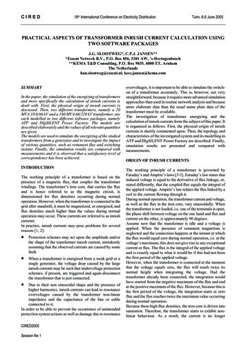
2Practical Transformerill —JHandbook 1.U\1Galvanometer(b)(a)(0(d)mz Da.c. source(e)(g)Figure 1.1 'Missing the boat' in the quest for the electricity-magnetism relationship, (a) When the switch is opened, the previously dimly-lit lamp flares upbrilliantly for a moment before extinguishing. This demonstrates energy storage inthe magnetic field, counter-EMF and self-inductance. What is lacking for transformer action is the proximity of a secondary coil to participate in these events, (b)The galvanometer in this true transformer circuit remains at zero as long as there isconstant battery current However, at about the instant of opening or closing of theswitch, there is a momentary deflection. This can easily be missed or misinterpreted, (c) We may suppose the permanent magnet is casually brought nearthe coil and then allowed to remain stationary. There is no evidence of electriccurrent in the coil. The observer, moreover, has a 'blind spot' to the effect ofwithdrawing the magnet, (d) The experimenter intuitively imparts motion to therod. Unfortunately, the rod is made of non-magnetic material, (e) The 'primary coil'is excited from an a.c. source. However, there is no mutual inductance and notransformer action because of the perpendicular relationship between the twocoils, (f) This is an appropriate setup for observing transformer action if an a.c.meter is used. However, if a d.c.-responding meter is used, its pointer will remainat zero for ordinary a.c. frequencies, (g) The bifilar secondary windings are inadvertantly connected in the series-bucking format. No net induced voltage isdetected. The same situation can arise with separate secondaries if they haveequal turns.of the transformer could have, and one can argue, should have, been recognized at a very early date. This is because the erstwhile experimenters longsuspected an elusive relationship between electricity and magnetism. Tostumble upon the techniques of freely converting one into the other wouldhave ushered in the electrical age at an earlier date. \ et, even after the evolution of the electromagnet, the very next step - the recognition of transformer action, did not occur immediately. Michael Faraday in England
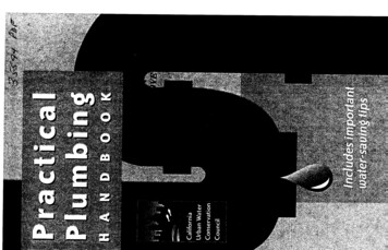
An overview of transformers in electrical technology 3and Joseph Henry in America finally postulated the laws of electromagneticinduction and performed the laboratory experiments that demonstratedtransformer action. Others, of course were involved in the complex chainof scientific and empirical events dealing with the behaviour of electricityand magnetism, but Faraday and Henry deserve credit for finally bringingthe device to fruition.The long-elusive essence of transformer action turned out to be embodied in the word change. Specifically, a magnetic field linking the turnsof an *input'and an 'output* coil had to undergo change by one way or another.It was not enough for a stationary permanent magnet to lie next to suchcoils. Nor was it sufficient for the d.c. from a battery to circulate throughone of the coils. One can sadly speculate that the inductive 'kick'of a galvanometer connected to one coil when the battery circuit to the other coil wasmade or broken must have elicited a 'so what' response from some of theearlier experimenters. Would you have thought otherwise? The elusivenessof this chance discovery is illustrated in Fig. 1.1.The ideal transformer - an ethereal but practical entityA good practical way of dealing with transformers is to consider them idealdevices, except where one or more of their non-ideal characteristics meritsfocused discussion. The validity of this approach lies in the fact that even thenarrow specialist finds it expedient to make assumptions and approximations in the otherwise rigorous relationships he uses. The features of theideal transformer are as follows:1. The ideal transformer has windings of perfect conductivity - there areno I R losses in either the primary or secondary coils.2. When endowed with a magnetic core, the ideal transformer exhibits nocore losses. That is, energy dissipation from hysteresis and eddy currentsin the core is zero.3. Perfect electromagnetic coupling exists between the windings. In otherwords, there is z ro leakage inductance.4. M exciting or magnetizing current is needed to set up the magneticflux.5. No capacitances are incorporated in the windings.6. The core exhibits linear magnetic characteristics (constant permeability).These are the basic'personality traits'of such a'sinless'device. One couldgo into greater detail by stating that eddy currents, proximity effect andskin effect should be absent in the windings. There should be no electromagnetic radiation. There should be immunity to effects of temperature on
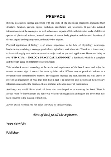
4Practical Transformer Handbookoperation. Most often, our ideal transformer will operate from a sinusoidalsource of a.c. current. Practicality is fortunately well-served by the initialassumptions of losslessness and linearity. Deviations from such perfection canthen be handled as the needs of the particular situation dictate (Fig. 1.2 illustrates these concepts).All magnetic-flux links both windings(zero leakage inductance)Magnetically-linear core(constant pernr)eabllity)ResistiveloadWatts outZero copper and core lossesFigure1.2 The basic features of the ideal transformer. This hypothetical creature,like perpetual motion, free energy or fulfillment of a politician's promises, is notfound in nature. However, the concept tends to be useful in dealing with manypractical aspects of real-life transformers. Among other things, the ideal transformer is 100% efficient and exhibits zero (perfect) voltage regulation.A practical question - why use an iron core intransformers?Students, neophytes and even those fairly well-versed in electrical technology often ponder, but feel embarrassed to ask, why 50/60 Hz transformershave to have iron cores. Why not just do away with the core and save onweight, cost and manufacturing problems? Such speculation is not to bethought of as foolish and is not on the level of those obsessed with perpetualmotion or free energy.It so happens that there is nothing in the transformer equation used byphysicists or electrical engineers that explicitly indicates the need for iron orother magnetic materials (see Fig. 1.3). Such equations simply tell us that somuch voltage is forthcoming from a certain magnetic flux density undergoing a certain rate of change. If one did not already know the outcome, itwould be perfectly natural to suppose that practical power transformerscould be designed around air cores. In attempting to build such a transformer, one would stumble upon a disconcerting practical fact of life: inorder to obtain the flux density required for handling volts and amperes
An overview of transformers in electrical technology 5rather than, say, microvolts and microamperes, the windings would be massive coils comprising perhaps miles of wire and would have impracticallyhigh resistances. The very geometry of such windings would self-defeat theobjective of developing high flux density Put another way, high inductance isrequired in the primary in order to keep the transformer exciting current ata small fraction of the allowable full-load current. Here again, such highinductance is not practical with a conductor that has sufficient crosssectional area to carry any practical current. The mathematics is notincorrect - it is conceivable that cryogenically cooled windings with zeroresistance could dispense with the conventional magnetic core.Is the iron coreindicated in thetransformer equation ? fciV/(10'B)where E is the number of volts induced in N turns.k is 4.44 for sine waves, or4.00 for square waves.N is the number of turns on a winding.Bm is the peak flux density.A is the cross-sectional area of the core.(Bm and A should be expressed in the same units),f is the frequency in Hz.Figure 1.3 The basic equation for transformer windings. Interestingly, thisequation says nothing about using iron or other magnetic cores in transformers.Without fore-knowledge of practical ramifications, it would be natural enough tosuppose a 50/60 Hz transformer could be designed with an air core.It is the high magnetic permeability of the iron or other core which saves theday by making possible high magnetic flux density with minimal magnetomotive force. That is, just a few ampere turns can produce much greater fluxdensity than is attainable with air as the 'core! Stated yet another way, weget high inductance from practical coils of wire.
6Practical Transformer HandbookWhy does a transformer transform?Once one gains insight into the need for an iron core or other magneticmaterial in low frequency transformers, the nature of the energy transferfrom the primary to the secondary winding often poses a dilemma.Although it should be quite clear that the source of the electrical energydelivered to the loaded secondary must be the a.c. power-line, why, indeed,should the primary obligingly draw and then transfer the required loadpower to the secondary? Inasmuch as the unloaded transformer is a verymiserly consumer of line current, some change must occur within the transformer when an appreciable load is imposed on the secondary.In order to get to the bottom of this situation, we must first consider thereason the unloaded transformer draws only a very small primary currentfrom the line. Although primary windings can have effective resistances ofa fraction of an ohm to several ohms in a wide variety of ordinary transformers and line voltages of tens and hundreds of volts are routinelyencountered, there appears to be opportunity for a heavy current flow evenwith an open-circuited secondary. The answer is that a transformer which isproperly designed will exhibit a sufficiently high inductance to keep theprimary current very low when there is no secondary load demand.It is relevant at this point to focus on the nature of inductive reactance; itexists because of a counter-EMF which opposes the impressed voltage.Thus, if 100 V are applied to the primary from the a.c. line, it is conceivablethat 99 V will be induced as the counter-EMF, effectively leaving only 1Vto force current in the primary. This surely is old hat to many readers, butlet's see what happens when a load is connected to the secondary. Because ofthe mutual magnetic flux threading through both windings, the secondarydevelops an induced voltage which now drives current through itself andthe load. These secondary ampere turns neutralize just the right amountof the primary ampere turns, or field intensity, to reduce the primaryinductance by the amount needed to draw the required line current. Thus,we may imagine that, in response to the secondary load, the primarycounter-EMF drops to 98 V, thereby allowing twice the line current to bedrawn by the primary.It is as if feedback information of increased secondary load causes theopening of a valve to admit more line current to the primary. As this takesplace, the relative primary and secondary ampere turns change in such away as to keep the mutualflux fairly constant. Thus, from no load to full load,the primary counter-EMF decreases to allow needed line current to supplythe secondary load circuit. Viewed from a slightly different viewpoint, onecan construe that increasing secondary load owes its existence to diminishing primary inductance. What might initially appear as a dull and passivedevice actually has an interesting and dynamic inner life.Let us look a bit more closely at the small primary current drawn by the
An overview of transformers in electrical technology 7unloaded transformer. Some of it simply supplies copper and core losses. Formany practical purposes, however, it is permissible to deal with a so-calledexcitation current. This is approximately the magnetization current whichsets up the mutual magnetic flux in the core. As already mentioned, thismutual flux is the energy transfer agent between the primary and secondary. Although primary and secondary ampere turns undergo change withvarying load conditions, these changes are such as to keep the mutual fluxnearly constant. The waveshapes and phase relationships of the excitingcurrent, the mutual flux and the induced secondary voltage are shown inFig. 1.4. The peaked excitation current shape betrays its largely third harmoniccontent.Excitation currentin primaryFigure 1.4 Waveforms in the iron core transformer. The non-sinusoidal excitationcurrent is driven from a sine wave source but is distorted due to the effect of thenon-linear iron core. Nevertheless, it produces the sinusoidally-shaped mutual flux.In response to the mutual flux, the induced voltage in the secondary is also a sinewave. The mutual flux leads the induced voltage by 90 . Note that the waveshaping property of the core simultaneously causes and removes distortion. In thismanner, the sinusoidal line voltage impressed on the primary again emerges as asine wave of induced secondary voltage.
8Practical Transformer HandbookInterestingly, the small excitation current is non-sinusoidal despite the factthat the transformer is driven from a sine wave source. However, the excitation current brings into being sinusoidal mutual flux, which then induces asine wave voltage in the secondary. Lest this prove confusing, it must bepointed out that these cause and effect relationships stem from the nonlinear magnetic characteristics of the iron core. Being small, the peakedexcitation current can often be neglected in practical transformer work. Itis nevertheless very important in transformer operation; in some systemswhere the third harmonic current is blocked, the secondary voltage itself,then becomes distorted often leading to various system disturbances andinterference with any communications circuits which might be in thevicinity.The fact that a mutual flux links both the primary and the secondaryturns means that induced voltages will be developed in these windings inthe same way. Stated another way, the same number of volts per turn orturns per volt will characterize both the primary and secondary windings.Thus, a secondary winding with the same number of turns as the primarywill exhibit the same induced voltage as the primary. If the secondaryhas twice as many turns as the primary, the induced secondary voltagewill be twice that of the primary; it is likewise true that a secondary withone-third the number of primary turns will be induced with one-thirdof the induced voltage in the primary. This is one of the most importantuses of transformers - stepping voltages up and down. Keep in mind,however, that available secondary current is necessarily the inverse of thevoltage change. If the voltage is doubled, the available current is halved; ifthe voltage is stepped-down to one-third of the primary voltage, the available secondary current is then three times the current consumption ofthe primary. These rules apply to both ideal and practical transformers designed to approach ideal characteristics. If it were otherwise, the transformer would be in the same league as perpetual motion machines.Historically, transformers decided the choice of a.c. over dc. utility power.A second, extremely useful, feature of transformers is impedance matching.This characteristic is the natural consequence of the voltage and currents inthe primary and secondary windings. Simply stated, an impedance connected to the primary appears at the secondary multiplied by the squareof the voltage gain in the secondary. Thus, if the secondary to primaryvoltage step-up is three, nine times the primary circuit impedance is 'seen'atthe secondary. Similarly, if the voltage step-down ratio going from primaryto secondary is one-half, the secondary will reflect one-quarter of the impedance associated with the primary. For most practical purposes, it isequally valid to say that the impedance transformation occurs as the squareof either the secondary to primary voltage ratio or their turns ratio. This isshown in Fig. 1.5.
An overview of transformers in electrical technology9ioon25nFigure 1.5 Typical example of impedance matching with a transformer. Theinternal resistance of the a.c. generator is 100 n. Maximum power transfer into a25 n resistive load is achieved with a transformer having a : 1 voltage stepdown ratio because the impedance reduction is then ( ) or \. The terms'resistance' and 'impedance' are often used interchangeably in this technique.(However, maximum power transfer can occur only if the resistive component ofimpedance is numerically matched and the reactive component is resonated ortuned out.)Core or shell-type transformer constructionImagine yourself to be a creative type of scientific experimenter back in theearly part of the nineteenth-century who had just heard of a physicist's claimthat electromagnetic coupling (transformer action) could be demonstratedby causing a time-varying magnetic circuit to encircle conductors so thatmagnetic flux and electric current were interlinked in a chain-like fashion.The implication here is that the electric current would become availablebecause of the physical relationship of the magnetic and electric elementsin such a setup.Perhaps you might suspect that the converse situation might also bevalid; that is, the conductors might be envisioned to encircle a magneticcircuit in such a way that the overall situation would still be the interlinkingof magnetic flux and electric conductors. One might go so far as to ponderwhether a time-varying current might serve to produce mutual induction(again, transformer action). With some experimentation to cast light onthese cause and effect relationships, you would likely discover the two basicpractical approaches in constructing transformers. Either wind the conductors around a magnetic core or wind the core around conductors.Although fabrication of modern transformers may not proceed in exactlythis way, the net effect remains as described. That is why we have so-calledcore-type and shell-type transformers. These constitute the two mainmethods of converting transformer theory into practical hardware. It isnot feasible to say which is better - there are too many trade-oflfs in cost,
10Practical Transformer Handbookefficiency, ease of manufacturing, thermal considerations, insulationmatters etc. to judge supremacy for either type.Single-phase core and shell-type transformers are shown in Fig. 1.6. Theyhave in common the fact that their cores are built up of thin laminations todiscourage the flow of eddy currents. For 50/60 Hz transformers theselaminations tend to be about 0.3 mm in thickness and are insulated eitherby natural surface oxidation or by a special coating of varnish or shellac. Inaudio frequency transformers, much thinner laminations are needed tokeep eddy current losses low.(a)(b)Figure 1.6 The two basic physical configurations of iron core transformers,(a) The core-type construction; the magnetic core is surrounded by the primary andsecondary windings, (b) The shell-type construction; the windings are surroundedby the core. Note that in both types, portions of the primary and secondary are sodistributed as to provide close physical separation. This minimizes leakage inductance. In drawings, however, it is customary to find the primary on one core legand the secondary on an opposite core leg.
An overview of transformers in electrical technology11Figure 1.7 Textbook example of a core-type three-phase transformer. Thistheoret
Transformer phasing in d.c. to d.c. converters 57 Transformer behaviour with pulse-width modulated waveforms 58 Current inrush in suddenly-excited transformers 62 Transformer temperature rise - a possible cooldown 64 High efficiency and high power fac