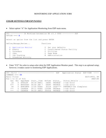
Transcription
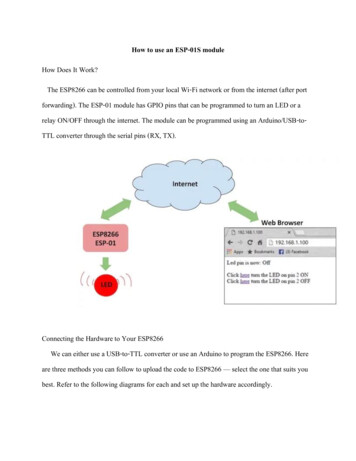
How to use an ESP-01S moduleHow Does It Work?The ESP8266 can be controlled from your local Wi-Fi network or from the internet (after portforwarding). The ESP-01 module has GPIO pins that can be programmed to turn an LED or arelay ON/OFF through the internet. The module can be programmed using an Arduino/USB-toTTL converter through the serial pins (RX, TX).Connecting the Hardware to Your ESP8266We can either use a USB-to-TTL converter or use an Arduino to program the ESP8266. Hereare three methods you can follow to upload the code to ESP8266 — select the one that suits youbest. Refer to the following diagrams for each and set up the hardware accordingly.
Pins are arranged in two rows, having 4 on each row. Some models have pin description on thePCB, which make it simple. On the top row you can find following pins from the left to the right:1.2.3.4.GND (Ground from power supply)GPIO2 (Digital I/O programmable)GPIO0 (Digital I/O programmable, also used for BOOT modes)RX – UART Receiving channelOn the bottom (second row) you can find:1.2.3.4.TX – UART Transmitting channelCH PD (enable/power down, must be pulled to 3.3v directly or via resistor)REST – reset, must be pulled to 3.3v)VCC -3.3v power supply
Power supply and current consumptionAll esp8266 arduino compatible modules must be powered with DC current from any kind ofsource that can deliver stable 3.3V and at least 250mA. Also logic signal is rated at 3.3v and theRX channel should be protected by a 3.3v divisor step-down. You should be careful when usingthis module with Arduino or other boards which supplies 5v, because this module usually do notcome with overpower protection and can be easily destroyed.Here is the declared power consumption from Espressif:
If you are going to use ESP-01 in a project that is powered by batteries or by solar power it ismandatory to know everything about ESP8266 arduino Sleep modes. Current version offers 3different sleep modes which can be triggered programmatically. ESP8266WiFi library offersspecific functions to call sleep modes which can take settings parameters that change the callbackjobs after wake-up like waking up with RF module powered off or on.The most important mode is DEEP SLEEP because of the very low power consumption ratesduring sleep. Deep sleep mode is very common in projects that do data-logging at specificintervals and idle between measurements.In order to take advantage of this mode when using esp8266 arduino compatible module, ESP-01standard, you need to make a little workaround and connect REST pin with the GPIO16 pin(which is not available in default 6 six pins).Here is an example how to do itAfter doing this connection you can use the following command to trigger the deep sleep mode:ESP.deepSleep(sleepTimeInSeconds * 1000000);
Talking with ESP-01 (AT / LUA / Arduino)ESP8266-01 gives you many methods to communicate with it through the RX/TX pins or over theair (OTA). The differences are not only in hardware but can be also in what kind of firmware isflashed out of the box. No matter what firmware comes default installed, you should be able toflash your preferred firmware by following the firmware flashing instruction from the datasheet.This module can be programmed using LUA code, Arduino code or directly through ATcommands and this gives us more freedom when embedding this device in our projects. Also,there are few python firmware modes but i haven’t had the chance to test them. I personallychoose to work with Arduino because of the past experience and tones of libraries available.As it comes, out of the box, this module is ready to talk via AT commands without any other extrasettings or configurations. There are many software applications which you can use tocommunicate via AT and have tones of readymade tools and functions which will makeeverything easier. I used ESPlorer and i totally recommend it, you can find it here. After booting,to be able to use AT commands, module should display “ready” on the serial monitor.Few basic AT commands examples:AT – response OKAT CWLAP – list nearby available WiFi networksAT GMR – check the firmware versionAT CWJAP ” access point name ”,” password ” – join WiFi network using credentialsAT CIFSR – get current allocated IP address
In order to be able to talk with the ESP8266 arduino compatible module, you need to choose away to connect it with your computer. You can communicate with the module via standard Serialcommunication RS232 by using an Arduino board as a proxy/bridgeArduino Uno differs from all preceding boards in that it does not use the FTDI USB-to-serialdriver chip. Instead, it features the Atmega16U2 (Atmega8U2 up to version R2) programmed as aUSB-to-serial converter. In order to use Arduino as a bridge, first you need to load an emptyprogram on it. After doing that, you need to make the following connections in order to work:UNORXTX3.3VGNDRSTCH PD OR ENESP-01SRXTX3.3VGNDRST3.3V
After that you should be able to see data and send AT commands in Serial Monitor byselecting Arduino’s COM port, setting a proper baudrate, default should be 115200, and make theadditional settings to read “Both NL & CRFirmware Over The Air (FOTA) solution in every embedded DIY or commercial project is ahighly desirable if not a required feature today, when every project core needs to scalable. So thepossibility to upload your code from a remote computer via Wi-Fi connection rather then Serial isa high advantage in every project. First you need FOTA needs needs prerequisites. First firmwareupload needs to be done via Serial, and if the OTA routines are correctly implemented in theprogram next uploads can be done over the air.Because the module needs to be exposed wirelessly, the chance to being hacked and loaded withmaleficent code exists. You can improve your security by setting custom port and password.Check functionalities from the ArduinoOTA library that may help you to boost security. Becauseof the complexity of this procedures we will cover the full story in a future article, but for now beaware that this option exists and it works pretty good.Another way to connect the esp8266 arduino module to computer is to use a TTL or FTDI USBto-serial dedicated module. There are plenty of them on the market and there are quite cheap, butmake no mistake, here quality does matter. You may encounter problems when working with it ifending up with a cheap one because of the differences in connections and also drivercompatibility.
Most used TTL / FTDI converters chips are CH340G, CP2102 and FT232RL. I personally usedthe first two ones and i have no problem when loading programs. Following connections need tobe loatCH PD OR EN3.3VI highly recommend you not to use the TTL 3.3v power supply because most of them are not ableto provide enough power to handle the esp8266 arduino compatible device. The embeddedvoltage regulator used on this module are not the happiest choice and you may get in trouble if itcannot support ESP peeks. If you choose to use an external power supply don’t forget to setup acommon ground in order to have a working circuit.
You can find TTL modules that have TX rated at 3.3v, if not, you shod step-down the TX channelto protect your ESP-01 module. You can see bellow a wiring scheme between ESP-01 andCP2102 which includes a reset button connected to ground, and also GPIO0 for boot switch.Here is a simple 3.3v divisor sketch using resistors:
In order to setup your Arduino IDE to work with your esp8266 arduino compatible module youneed to make the following steps:1. Connect your ESP8266-01 Module to PC2.Open your Arduino IDE3.Go to File - Preferences4.Add this link to Additional Board Manager5.Go to Tools - Board Manager6.Find ESP8266 board set and activate it7.Select Generic ESP8266 board from Tools- Boards8.Choose your programmer COM port9.You are ready to go!
Now, to be able to download the program to your ESP-01 module, you first need to put yourdevice in the proper BOOT mode (Download code from UART). ESP8266-01 have the followingboot modes:MTDO SDIODownloadcode fromUARTBoot fromSPI FlashBoot fromSD-cardAfter resetting the module in Download code from UART you should see a message containing“boot mode: [1,6]” in the serial monitor, if you are on the correct baudrate. A wrong baudratesetting will display garbage text / characters or nothing at all. After that you should be able toupload your sketch to ESP8266. When upload is done, module should reset itself. Don’t forget topull HIGH the GPI0 or the module will get in Download mode again and you will not be able tosee it working. The module can be rebooted at any time by pulling REST pin to LOW. After eachreset it will follow the boot sequence and program loading.
Once the ESP8266 board is installed and activated in Arduino IDE, you will be able to includeall ESP WiFi libraries and examples that comes with the package. The most used library isESP8266WiFi which offers many implementation examples like WiFiClient, WiFiServer,WiFiAccessPoint etc. You can find allot of projects examples over the internet, I for example,found great ideas on arduino.cc projecthub. Here is a simple Arduino blink example which youcan use to test the esp module with the built in LED:/*ESP8266 Arduino Blink by Simon PeterBlink the blue LED on the ESP-01 moduleThis example code is in the public domainThe blue LED on the ESP-01 module is connected to GPIO1(which is also the TXD pin; so we cannot use Serial.print() at the same time)Note that this sketch uses LED BUILTIN to find the pin with the internal LED*/void setup() {pinMode(LED BUILTIN, OUTPUT); // Initialize the LED BUILTIN pin as an output}
// the loop function runs over and over again forevervoid loop() {digitalWrite(LED BUILTIN, LOW); // Turn the LED on (Note that LOW is the voltage level// but actually the LED is on; this is because// it is acive low on the ESP-01)delay(1000);// Wait for a seconddigitalWrite(LED BUILTIN, HIGH); // Turn the LED off by making the voltage HIGHdelay(2000);}// Wait for two seconds (to demonstrate the active low LED)
Off course, after that you can try a more complex example by loading a ESP8266 Arduino WiFiClient example program that sends data via WiFi to the data.spakfun.com iot platform:/** This sketch sends data via HTTP GET requests to data.sparkfun.com service.** You need to get streamId and privateKey at data.sparkfun.com and paste them* below. Or just customize this script to talk to other HTTP servers.* ESP8266 Arduino example*/#include ESP8266WiFi.h const char* ssid "your-ssid";const char* password "your-password";const char* host "data.sparkfun.com";const char* streamId ".";const char* privateKey ".";
void setup() {Serial.begin(115200);delay(10);// We start by connecting to a WiFi int("Connecting to ");Serial.println(ssid);WiFi.begin(ssid, password);while (WiFi.status() ! WL CONNECTED) {delay(500);Serial.print(".");}Serial.println("");
Serial.println("WiFi connected");Serial.println("IP address: ");Serial.println(WiFi.localIP());}int value 0;void loop() {delay(5000); value;Serial.print("connecting to ");Serial.println(host);// Use WiFiClient class to create TCP connectionsWiFiClient client;const int httpPort 80;if (!client.connect(host, httpPort)) {Serial.println("connection failed");
return;}// We now create a URI for the requestString url "/input/";url streamId;url "?private key ";url privateKey;url "&value ";url value;Serial.print("Requesting URL: ");Serial.println(url);// This will send the request to the serverclient.print(String("GET ") url " HTTP/1.1\r\n" "Host: " host "\r\n" "Connection: close\r\n\r\n");unsigned long timeout millis();
while (client.available() 0) {if (millis() - timeout 5000) {Serial.println(" Client Timeout !");client.stop();return;}}// Read all the lines of the reply from server and print them to Serialwhile(client.available()){String line erial.println();Serial.println("closing connection");}
Or if you need to make a server in your network, you can try ESP8266 Arduino Wifi Serverexample program:/** This sketch demonstrates how to set up a simple HTTP-like server.* The server will set a GPIO pin depending on the request* http://server ip/gpio/0 will set the GPIO2 low,* http://server ip/gpio/1 will set the GPIO2 high* server ip is the IP address of the ESP8266 Arduino module, will be* printed to Serial when the module is connected.*/#include ESP8266WiFi.h const char* ssid "your-ssid";const char* password "your-password";// Create an instance of the server// specify the port to listen on as an argumentWiFiServer server(80);
void setup() {Serial.begin(115200);delay(10);// prepare GPIO2pinMode(2, OUTPUT);digitalWrite(2, 0);// Connect to WiFi int("Connecting to ");Serial.println(ssid);WiFi.begin(ssid, password);while (WiFi.status() ! WL CONNECTED) {delay(500);
ln("WiFi connected");// Start the serverserver.begin();Serial.println("Server started");// Print the IP addressSerial.println(WiFi.localIP());}void loop() {// Check if a client has connectedWiFiClient client server.available();if (!client) {return;}
// Wait until the client sends some dataSerial.println("new client");while(!client.available()){delay(1);}// Read the first line of the requestString req lient.flush();// Match the requestint val;if (req.indexOf("/gpio/0") ! -1)val 0;else if (req.indexOf("/gpio/1") ! -1)val 1;else {
Serial.println("invalid request");client.stop();return;}// Set GPIO2 according to the requestdigitalWrite(2, val);client.flush();// Prepare the responseString s "HTTP/1.1 200 OK\r\nContent-Type: text/html\r\n\r\n !DOCTYPEHTML \r\n html \r\nGPIO is now ";s (val)?"high":"low";s " /html \n";// Send the response to the clientclient.print(s);delay(1);
Serial.println("Client disonnected");// The client will actually be disconnected// when the function returns and 'client' object is detroyed}
And in the last example an ESP8266 Arduino WiFi Access Point which hosts a web server iscreated:/* Create a WiFi access point and provide a web server on it.ESP8266 Arduino example*/#include ESP8266WiFi.h #include WiFiClient.h #include ESP8266WebServer.h /* Set these to your desired credentials. */const char *ssid "ESPap";const char *password "thereisnospoon";ESP8266WebServer server(80);/* Just a little test message. Go to http://192.168.4.1 in a web browser* connected to this access point to see it.
*/void handleRoot() {server.send(200, "text/html", " h1 You are connected /h1 ");}void setup() ;Serial.print("Configuring access point.");/* You can remove the password parameter if you want the AP to be open. */WiFi.softAP(ssid, password);IPAddress myIP WiFi.softAPIP();Serial.print("AP IP address: ");Serial.println(myIP);server.on("/", handleRoot);server.begin();Serial.println("HTTP server started");
}void loop() {server.handleClient();}
Power supply and current consumption All esp8266 arduino compatible modules must be powered with DC current from any kind of source that can deliver stable 3.3V and at least 250mA.Also logic signal is ra