Transcription
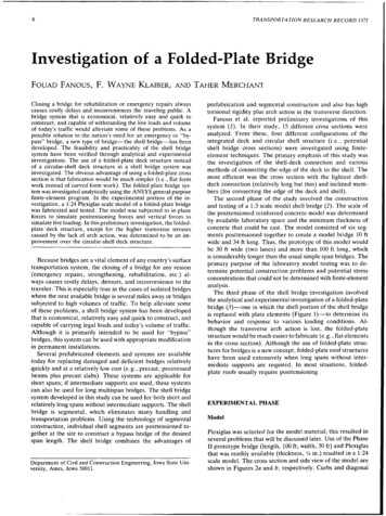
ENCE 717BRIDGE ENGINEERINGABUTMENT/PIER DESIGNC. C. Fu, Ph.D., P.E.The BEST CenterUniversity of MarylandDecember 2008Abutment Types(a) Typical gravityabutmentw/wing walls(b) U-abutment(c) Spill-throughabutment(d) Pile bentabutment withstub wingsFunction of AbutmentsAbutments are used at the endsof bridges to retain theembankment and carry thevertical and horizontal forcesfrom the superstructure. Theycould be designed as piers orretaining walls and they shouldbe able to withstand againstoverturning and sliding. Thefootings should be designed toavoid differential settlement andexcessive horizontalmovements.Full Height AbutmentA full height abutmentis constructed at thelower level roadwayand should support theentire embankment.This abutment is costlyand is generally used incongested urban andmetropolitan areawhere structure depthis critical.1
Semi-stub AbutmentA semi-stub abutment is constructed somewherebetween the top and bottom of an embankmentand its height is between height of full and stubabutment.Integral AbutmentStub AbutmentA stub abutment is built at the top of embankment slope andis considered as the best type of abutment for avoidingrough and settled approach pavements. A stub abutment iseconomical but gives a longer span length and a highersuperstructure cost. However, the overall structure would beless costly than other alternateBenefit of Integral Abutment Integral abutment isstub abutment onsingle row of flexiblepiles andconstructed withoutjoints. Integralabutments allow theexpansion andcontraction throughmovement at theabutments. Cost saving by using less piling and simple design, eliminatingjoint, and less maintenanceMaximum acceptable maximum range: Steel :up to 200 –300 ft Concrete:300 – 400 ft Prestressed concrete:300 – 450 ftBackfill at abutment should be free-draining material andcompacted to 95%. Proper compaction is required to eliminatesettlement of backfill. More attention should be given tobackfilling including drainage details and potential use ofgeotextile to stabilize the backfill.Skew over 30 degree should not be usedIntegral abutment bridges are limited to pile supported abutmentsand drill shaft can not be usedLonger than normal approach slab is required.2
Semi-integral AbutmentConventional stubabutment is fixedwith in position withexpansion andcontractionmovement of bridgesuperstructure. Asemi-integral bridgecan accommodateup to 400 feet and45 skew angle.Open/Spill-through AbutmentOpen or Spill -through Abutment is used where anadditional span will be added at a later date. It isessentially a pier functioning as an abutment. The mainproblem with this type of abutment are compaction ofembankment around the abutment, early settlement anderosion.Pier Fundamentals Whenever possible water crossing piers should bealigned with the stream flow to avoid the creation ofeddies and turbulence which can result in scour.Two piers close to each shore line may be morehydraulically efficient and economical to constructthan one deep water pierWhen pier is located in marine environments,reinforcement should be corrosion protected andconcrete should include corrosion inhibitors.To offset abrasive action of water, bridge pier shouldhave HPC (High Performance Concrete) outer layersor form liners protection.Pier Fundamentals (cont.)It is preferred that the pier shaft should be solid to aheight of 3 feet above navigable elevation or 2 feetabove 100 year flood.The upstream face of piers should be round or V shapedto improve hydraulics. If ice and /or debris is problem, theupstream face should be battered 15 degree andarmored with steel angle to a point 3 feet above designhigh water.The wing walls on the upstream side should be alignedto direction the flow through the bridge opening.In case where wing walls are at or near the water’s edge,the wing walls should be flared to improve the hydraulicentrance condition.3
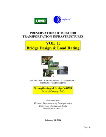
Column Bent PierThe column bent pier that consists of a pier cap withcolumns supporting an individual or a continuous footingis widely used on grade separation structures.TypicalTrapezoidalPiers forGradeSeparationStructuresWall PierTypicalHammerheadPiers forGradeSeparationStructuresA wall pier is used for most stream crossings to avoidcollecting of debris and floating ices between columns.A wall type pier consisting of a single row of piles,especially H-piles, encased with concrete to form awall provides more resistance to ice and debris andallows debris to pass through4
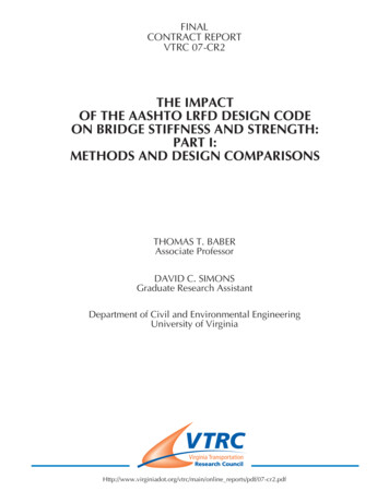
Hammerhead PierA solid shaft pier or T pier is used for major streamcrossings where heavy loads, tall piers or sizeable ice anddebris loads may occur. The hammerhead type T pier isgenerally cheaper than the solid wall pier because itrequires fewer quantities of materials and a smallercofferdam to construct it on stream crossings.WaterwayCrossingPiersPile Installation MethodsFoundation Types Spread Footings (control bearing pressure, totalsettlement and differential settlement)1.Individual Footings2.Combined FootingsDriven Piles 1.2. Displacement piles (solid sections or hollow sections witha closed end)Non-displacement piles (less shaft friction, H-piles andopen-ended sections)Driven Shafts (Referred to as drilled sub-piers orcaissons) 1.2.3. Driven preformedpilesImpact methodsStatic installationVibratory drivingDriven cast-insitu pilesBored cast-insitu piles5
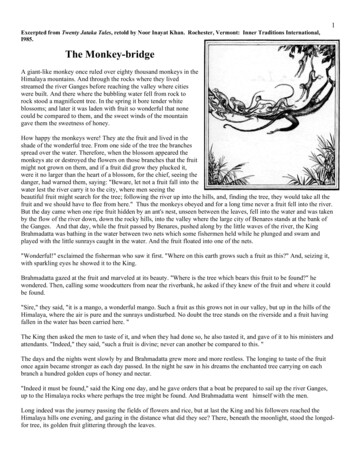
Summary of Frequently used PilesPile BentPile bent piers consisting of a row of piles with aconcrete cap encasing the pile tops are the simplest andmost economical type of pier. They are used for streamcrossings where the maximum height from the top ofpier to stream bed is under 20 ft.(6 m) and there is noice or debris problem.Advantage/Disadvantage?Possible Configurations for aTypical Four-span Highway BridgesDrilled Shaft(DrilledSubpier,Caisson)6
Bearings(recommended by steel industry)Bearing TypesUse elastomeric if possible Elastomeric -approximately 225 eaUse pot bearing next Pot bearingPot Bearing -approximately 800 eaOthers Spherical Bearing -approximately 1200 eaBronze Rocker -approximately 600 eaElastomericBearing Types (cont.)SlidingRockerSpherical BearingDistribution of Longitudinal Forces toFixed and Expansion PiersThe following distribution modes of longitudinal forces areoften assumed: Expansion bearings resist only thermal, while the fixedbearing resists all longitudinal forces associated with windand traffic loads. The forces released from the expansion bearings due tolive load vibration must be carried by the fixed pier. Expansion bearings carried loads to their friction capacity,computer as the dead load reaction multiplied by a frictioncoefficient. Any additional loads must be resisted at thefixed pier With massive, stiff abutments at the ends of abridge,design intermediate piers for vertical loads only.7
Loads resisted by the substructure Dead load from the superstructureDead load of the substructureLive load and impact from the superstructureWind loads on the super- and substructuresWind load on the live loadCentrifugal force from the superstructureLongitudinal force from live loadDead load friction from bearingsEarth pressureStream flow pressureIce pressureEarthquake forcesThermal and shrinkage forcesShip impact forcesLive Load Distribution Live load reactions obtained from design ofindividual members of the superstructureshould not be used for substructure design,resulting un-economic sections.For the calculation of the actual beamreactions on the pier, the maximum lanereaction can be applied within the designtraffic lanes as wheel loads, and thendistributed to the beams assuming the slabbetween beams to be simply supported.Multi-lane reduction shall be considered.Live LoadDistributionTransverse Loading: Wind Loadsa. Wind load on the superstructureWssuper,t (Area of exteriorbeam, roadway slab andparapet per linear ft as seenin the transverse elevation) x(Average span length of twospans adjacent to the pierunder consideration) x(Unit transverse wind load asspecified in AASHTO LRFD3.8.1.2.2)8
Transverse Loading: Wind Loadsb. Wind load on the substructureWssub,t (Area ofexposed substructureas seen in thetransverse elevation) x(Unit transverse windload as specified inAASHTO LRFD3.8.1.2.3) assumedbase wind pressure of0.04 ksfTransverse Loading: Wind Loadsd. Wind overturning (upward) forcesTransverse Loading: Wind Loadsc. Wind load on moving live loadWLt (Average span length of two spansadjacent to the pier under consideration) x(Unit wind on a moving live load as specified inAASHTO LRFD 3.8.1.3) by an interruptablemoving force of 0.1 klf acting normal to, and 6ft above the roadwayTransverse Loading: Centrifugal ForceWSoverturn (The magnitude and application of thislongitudinal line load is specified in AASHTO LRFD3.8.2)CE (calculate and apply the horizontal radial forcedue to structure curvature as specified in AASHTO LRFD3.6.3) at 6 ft above the roadway surface(A vertical upward wind force of 0.02 ksf) x (thewidth of the deck, including parapets andsidewalks) at the windward quarter-point of thedeck.C 4/3 (v2/gR)9
Transverse Loading: Other ForcesLoads may include the influence of streamcurrent (WA), floating or freezing ice (IC),drift, earth pressure (EH, ES, LS, DD),vessel collision (CV) and earthquake forces(EQ), or in the case of rigid frame bentpiers, internal stresses due to temperaturechange and shrinkage forces (TU, TG, SH,CR, SE) in the appropriate group ofloadings of AASHTO LRFD 3.9-3.14Longitudinal Loading: Wind Loadsa. Wind load on the superstructureWSsuper,L (Area of the exterior beam; roadway slaband parapet per linear foot as seen in the transverseelevation) x (Bridge length) x(Unit longitudinal wind load as specified in AASHTOLRFD 3.8.1.2.2)b. Wind load on the substructureWssub,L (Area of the exposed substructure asseen in the longitudinal elevation) xLongitudinal Loading: Braking ForceBR Max. of (25% design truck of tandem, 5%design truck or tandem lane) x(number of design traffic lanes loaded with onedirection traffic) x(Reduction factor for lane loadings, AASHTO) at 6 ftabove the roadway surfaceLongitudinal Loading: Wind Loadsc. Wind load on moving live loadWLL (Average span length of two spans adjacent to thepier under consideration) x(Unit wind on a moving live load as specified in AASHTOLRFD 3.8.1.3) by the components of parallel force of aninterruptable moving force of 0.1 klf acting at 6 ft abovethe roadway(Unit longitudinal wind load as specified inAASHTO LRFD 3.8.1.2.3)10
BRIDGE ENGINEERING ABUTMENT/PIER DESIGN C. C. Fu, Ph.D., P.E. The BEST Center University of Maryland December 2008 Function of Abutments Abutments are used at the ends of bridges to retain the embankment and carry the vertical and horizontal forces from the superstructure. TheyFile Size: 363KB