Transcription
6. Intersection Design6. INTERSECTION DESIGNINTRODUCTION . 1ESSENTIAL PRINCIPLES OF INTERSECTION DESIGN . 1INTERSECTION GEOMETRY . 2Intersection Skew. 3Corner Radii . 4Curb Extensions . 7Crosswalk and Ramp Placement . 10On‐Street Parking Near Intersections . 13Right‐Turn Channelization Islands . 13YIELD AND STOP CONTROLLED INTERSECTIONS . 16SIGNALIZED INTERSECTIONS . 16Operational Design . 17Phasing . 17ROUNDABOUTS. 22Advantages and Disadvantages . 23General Design Elements of Roundabouts . 24Roundabout Design Criteria. 25Operations and Analysis . 26Single‐Lane Roundabouts . 26Multi‐Lane Roundabouts . 27Mini‐Roundabouts . 28Neighborhood Traffic Circles . 29
6. Intersection Design(Credit: Kimley‐Horn and Associates, Inc.)
6. Interseection DesignnINTRODDUCTIONMost coonflicts betwween roadway users occcur atintersecctions, wheere traveleers cross eachother’s path. GGood interrsection designindicatees to those aapproachingg the interseectionwhat t hey must ddo and whho has to yyield.Exceptioons to this iinclude places where sppeedsare loww (typically leess than 20 mph) or where ashared space desiggn causes ussers to apprroachintersecctions withh caution. Conflicts forpedestrrians and biccyclists are exacerbatedd dueto theirr greater vuulnerability, lesser size,, andreducedd visibility tto other ussers. MultimmodalLiively intersectioon (Credit: Dann Burden)intersecctions operate with pedestrians,bicycless, cars, busees, trucks, annd in some ccases,Tdiverse uses of inttersections involve a hhigh level oof activity aand shared use.trains. TheIntersecttions have thhe unique chharacteristicc of accommmodating thee almost constant occurrrenceof conflicts betweenn all modess, and mostt collisions on major tthoroughfarees take placce atintersecttions. This chharacteristicc is the basis for most in tersection ddesign standards, particuularlyfor safetty. Designingg multimodal intersectiions with thhe appropriate accommmodations foor allusers is performedpono a case‐by‐‐case basis. TheT designeer should beggin with an understandiing ofthe commmunity objecctives and priorities relaated to desiggn tradeoffs.This chaapter describes designn considerattions in in tersection geometry aand interseectionsignalizattion, as well as roundabouts and otherofeaturres to improove safety, aaccessibility, andmobility for all userrs. The bennefits and constraints oof each featture are exxamined andd theappropriate use and design of eaach feature area describeed.ESSENTTIAL PRINCCIPLES OF INTERSECTTION DESIGGNThe folloowing interrsection dessign principples apply ttoserve all users of inteersections: “Busyy streets aare not frriendlyto crooss."‐ (Broward Complete StreetsGoodGintersection designns are compaact.survey resppondent)MinimizeMconnflicts betweeen modes.UnusualUconfflicts should be avoided.AccommodatAte all modess with approopriate leveelsof service.Simple right‐aangle intersections are best for all users since many interssection probblemsare worsenedd at skewed and multi‐leegged intersections.Free‐flowing movementss should be avoided.aBrooward Compplete Streetss Guideliness Chapter 66, Page 6‐1
6. Intersection Design Avoid elimination of travel modes from the typical section due to intersection designconstraints.Access management practices should be used to remove additional vehicular conflictpoints near the intersection.Signal timing should consider the safety and convenience of all users and should nothinder bicycle or foot traffic with overly long waits or insufficient crossing times.Ensure intersections are fully accessible.Intersections should be designed to serve all types of users comfortably, even on wide arterialboulevards (Credit: Kimley‐Horn and Associates, Inc.)INTERSECTION GEOMETRYIntersection geometry is a critical element of intersection design, regardless of the type oftraffic control used. Geometry sets the basis for how all users traverse intersections andinteract with each other. The principles of intersection geometry apply to both streetintersections and freeway on‐ and off‐ramps.Intersection layout is primarily comprised of the alignment of the legs; width of traffic lanes,bicycle lanes, and sidewalks on each approach (number of lanes, median and roadsideelements); and the method of treating and channelization of turning movements. The design ofan intersection’s layout requires a balance between the needs of pedestrians, bicyclists,vehicles, freight and transit in the available right‐of‐way.Broward Complete Streets Guidelines Chapter 6, Page 6‐2
6. Intersection DesignIntersections are comprised of a physical area. The functional area is where drivers makedecisions and maneuver into turning movements. The three parts of a functional area includethe perception‐reactions distance, maneuver distance and storage distance. AASHTO’s Policy onGeometric Design of Highways and Streets, addresses the issues and provides guidance for thedetail geometric design of the functional area. The basic types of intersections in urbancontexts include the T‐intersection, cross intersection, multi‐leg intersection, and modernroundabout.INTERSECTION SKEWSkewed intersections are generally undesirable and introduce the following complications forall users: The travel distance across the intersection is greater, which increases exposure toconflicts and lengthens signal phases for pedestrians and vehicles.Skews require users to crane their necks to see other approaching users, making it lesslikely that some users will be seen.Obtuse angles encourage speeding.To alleviate the problems with skewed intersections, several options are available: Every reasonable effort should be made to design or redesign the intersection closer toa right angle. Some right‐of‐way may have to be purchased, but this can be offset by thelarger area no longer needed for the intersection, which can be sold back to adjoiningproperty owners or repurposed for a pocket park, rain garden, greenery, etc.Converting stop‐controlled and signalized intersections into modern roundabouts.Roundabouts’ benefits include improved safety, speed reduction, aesthetics andoperational functionality and capacity.Pedestrian refuges should be provided if the crossing distance exceeds approximately 40feet.General use travel lanes and bike lanes may be striped with dashes to guide bicyclistsand motorists through a long undefined area.Broward Complete Streets Guidelines Chapter 6, Page 6‐3
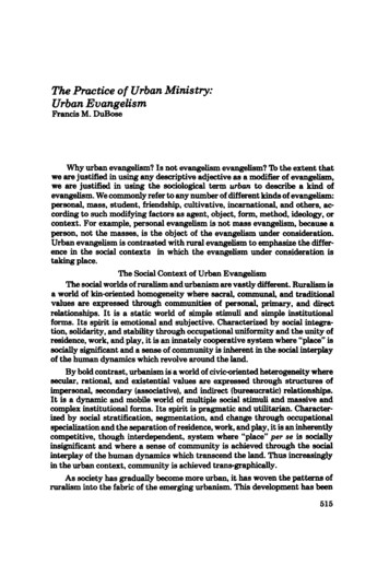
6. Intersection DesignRealigning the skewed intersection in the graphic on the left to the right‐angle connection in the graphic on theright results in less exposure distance and better visibility for all users.(Credit: Michele Weisbart)Multi‐leg intersections (more than two approaching roadways) are generally undesirable.Making it clear to drivers that pedestrians use the intersections, and providing properindication to pedestrians where the best place is to cross are some or the problems with thistype of intersections. Multi‐leg intersections also present the following complications for allusers: Multiple conflict points are added as users arrive from several directions.Users may have difficulty assessing all approaches to identify all possible conflicts.At least one leg will be skewed.Users must cross more lanes of traffic and the total travel distance across theintersection is increased.To alleviate the problems with multi‐leg intersections, several options are available: Every reasonable effort should be made to design the intersection so there are no morethan four legs. This is accomplished by removing one or more legs from the majorintersection and creating a minor intersection further up or downstream.As an alternative, one or more of the approach roads can be closed to motor vehicletraffic, while still allowing access for pedestrians and bicyclists.Roundabouts should be considered.Pedestrian refuges should be created if the crossing distance exceeds approximately 40feet.General use travel lanes and bike lanes may be striped with dashes to guide bicyclistsand motorists through a long undefined area.CORNER RADIICorner radii (also called curb return radii) are the curved connection of curbs in the corners.This intersection geometry feature has a significant impact on the comfort and safety of non‐Broward Complete Streets Guidelines Chapter 6, Page 6‐4
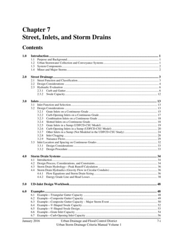
6. Intersection Designmotorized users. The use of the smallest practical corner radii to shorten the length of thecrosswalk is usually desirable. Small corner radii provide the following benefits: Smaller, more pedestrian‐scale intersections resulting in shorter crossing distances Slower vehicular turning speeds Reduced pedestrian crossing distance and crossing time Better geometry for installing perpendicular ramps for both crosswalks at each corner Simpler, more appropriate crosswalk placement, in line with the approaching sidewalksTighter corner radii reduce crossing distance and slow turning traffic.(Credit: Michele Weisbart)Broward Complete Streets Guidelines Chapter 6, Page 6‐5
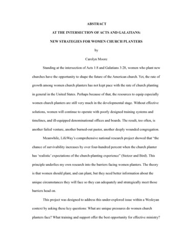
6. Intersection Design When designing corner radii for complete streets, the default design vehicle should bethe passenger (P) vehicle. Therefore, the default corner radius is 15 feet. Larger designvehicles should be used only where they are known to regularly make turns at theintersection, and corner radii should be designed based on the larger design vehicletraveling at crawl speed. In addition, designers should consider the effect that bicyclelanes and on‐street parking have on the effective radius, increasing the ease with whichlarge vehicles can turn.The effective corner radius controls turning speeds and the ability of large vehicles to turn.(Credit: Michele Weisbart) Encroachment by large vehicles is acceptable onto multiple receiving lanes. When adesign vehicle larger than the passenger (P) vehicle is used, the truck or bus should beallowed to turn into all available receiving lanes. As described in Chapter 5, “TraveledWay Design,” larger, infrequent vehicles (the “control vehicle”) can be allowed toencroach on multiple departure lanes and partway into opposing traffic lanes.Corner radii may need to be larger where occasional encroachment is not acceptable.Broward Complete Streets Guidelines Chapter 6, Page 6‐6
6. Intersection DesignCorner radii can be kept smaller by allowing trucks and buses to turn into multiple receiving lanes.(Credit: Michele Weisbart)CURB EXTENSIONSWhere on‐street parking is allowed, curb extensions (also called bulb‐outs) should replace theparking lane at crosswalks. Curb extensions should be the same width as the parking lane. Theappropriate corner radius should be applied based on the guidance in the section above. Due toreduced road width, the corner radius on a curb extension may need to be larger than if curbextensions were not installed.Curb extensions offer many benefits related to livability: Reduced pedestrian crossing distance resulting in less exposure to vehicles and shorterpedestrian clearance intervals at signals Improved visibility between pedestrians and motorists A narrowed roadway, which has a potential traffic calming effect Additional room for street furniture, landscaping, and curb ramps Slower turning vehicles Additional on‐street parking potential due to improved sight lines at intersections. Sincecurb extensions allow pedestrians to walk out toward the edge of the parking lanewithout entering the roadway, pedestrians can better see vehicles and motorists canbetter see pedestrians. Management of streetwater runoff Separate parking maneuvers from turning vehicles.Broward Complete Streets Guidelines Chapter 6, Page 6‐7
6. Intersection DesignCurb extensions improve sight distance between pedestrians andmotorists, possibly allowing additional on‐street parking.(Credit: Michele Weisbart)To fully achieve livability goals, the curb extension and parking area can be integrated into thefurniture zone portion of the sidewalk corridor. This technique involves using similar surfacematerials for the curb extension, parking area, and the sidewalk as shown in the figure below.Instead of the curb extensions appearing to jut out into the street, the parking appears as“parking pockets” in the furniture zone. Curb extensions can be used in any context zone, butthey should be standard in T‐5 and T‐6. Curb extensions must always be outside of the width ofthe bike lane or the location within the traveled way that bicyclists are expected to ride.Broward Complete Streets Guidelines Chapter 6, Page 6‐8
6. Intersection DesignIntegrating curb extensions and on‐street parking into the sidewalk corridorenhances pedestrian safety and the walking experience. (Credit: Michele Weisbart)To reinforce this design where street grades permit, the gutter line and drainage grates shouldbe placed between the travel lane and the parking lane/curb extensions. This is called a “valleygutter” and creates a stronger visual cue separating the parking lane from the bicycle lane ortravel lane. It can sometimes allow existing drainage infrastructure to be left in place.An example of integrating curb extensions and parking into the sidewalk corridor byplacing a valley gutter between the parking and the traveled way.(Credit: Michele Weisbart)Broward Complete Streets Guidelines Chapter 6, Page 6‐9
6. Intersection DesignCROSSWALK AND RAMP PLACEMENTCrosswalks are used to assist pedestrians in crossing the street. Florida State Statute 316makes it clear that unmarked crosswalks can exist only at intersections whereas markedcrosswalks can exist at intersections or elsewhere. This is consistent with the Manual onUniform Traffic Control Devices (MUTCD). Crosswalks and ramps at intersections should beplaced so they provide convenience and safety for pedestrians. The following recommendedpractices will help achieve these goals: Allow crossings on all legs of an intersection, unless there are no pedestrian accessibledestinations on one or more of the corners. Closing a crosswalk usually results in apedestrian either walking around several legs of the intersection, exposing them tomore conflicts, or crossing at the closed location, with no clear path or signal indicationas to when to cross.Provide marked crosswalks at signalized intersections.Provide marked crosswalks at an intersection approach controlled by stop sign.Marked crosswalks shall be 10 feet wide in urban zones.Strongly consider providing marked crosswalks at major unsignalized intersections withmedians for pedestrian refuges or on one‐way streets.Place crosswalks as close as possible to the desire line of pedestrians, which is generallyin line with the approaching sidewalks.Provide as short as possible a crossing distance to reduce the time that pedestrians areexposed to motor vehicles; this is usually as close as possible to right angles across theroadway, except for skewed intersections.Ensure that there are adequate sight lines between pedestrians and motorists. Thistypically means that the crosswalks should not be placed too far back from theintersection.When a raised median is present, extend the nose of the median past the crosswalkwith a cut‐through for pedestrians.Provide one ramp per crosswalk (two per corner for standard intersections with noclosed crosswalks). Ramps must be entirely contained within a crosswalk (the crosswalkcan be flared to capture a ramp that cannot be easily relocated). Align the ramp runwith the crosswalk when possible, as ramps that are angled away from the crosswalkmay lead some users into the intersection.Broward Complete Streets Guidelines Chapter 6, Page 6‐10
6. Intersection Design At intersections where roads are skewed or where larger radii are necessary for trucks,it can be difficult to determine the best location for crosswalks and sidewalk ramps. Inthese situations, it is important to balance the recommended practices above. Tightercurb radii make implementing these recommendations easier.At signalized crossings, shared‐use path crossing, or any other particular high emphasiscrosswalk markings (ladder style crosswalk) should be used to increase visibility.Curb ramp opening on shared‐use path shall be the same width as the path itself.Detectable warning surfaces shall be provided per MUTCD 3B.18 and 49 Code of FederalRegulations Part 37.Pedestrian warning sign (W11‐2) at a high emphasis crosswalk. Note the yield bars (series of isosceles trianglespainted on the approach to the crosswalk.(Credit: Kimley‐Horn and Associates, Inc.)Broward Complete Streets Guidelines Chapter 6, Page 6‐11
6. Intersection DesignOne curb ramp per crosswalk should be provided at corners. Ramps should align withsidewalks and crosswalks.(Credit: Michele Weisbart)Broward Complete Streets Guidelines Chapter 6, Page 6‐12
6. Intersection DesignON‐STREET PARKING NEAR INTERSECTIONSOn‐street parking should be positioned far enough away from intersections based on providingadequate sight distance to allow for good visibility of pedestrians preparing to cross the street.Curb extensions allow parking to be placed closer to the intersection since pedestrians canqueue in a more visible location for which parked cars do not block the sight line of anoncoming motorist.RIGHT‐TURN CHANNELIZATION ISLANDSIn the context suburban zone (T3) through urban core zone (T6), high speed channelized right‐turns are inappropriate because they create conflicts with pedestrians. Right‐turn lanes shouldgenerally be avoided as they increase the size of the intersection, the pedestrian crossingdistance, and the likelihood of right‐turns‐on‐red by inattentive motorists who do not noticepedestrians on their right. However, where there are heavy volumes of right turns(approximately 200 vehicles per hour or more), a right‐turn lane may be the best solution toprovide additional vehicle capacity without adding additional lanes elsewhere in theintersection. For turns onto roads with only one through lane and where truck turningmovements are rare, providing a small corner radius at the right‐turn lane often provides thebest solution for pedestrians’ safety and comfort.At intersections of multi‐lane roadways where trucks make frequent right turns, a raisedchannelization island between the through lanes and the right‐turn lane is a good alternative toan overly large corner radius and enhances pedestrian safety and access. If designed correctly,a raised island can achieve the following objectives: Allow pedestrians to cross fewer lanes at a timeAllow motorists and pedestrians to judge the right turn/pedestrian conflict separatelyReduce pedestrian crossing distance, which can improve signal timing for all usersBalance vehicle capacity and truck turning needs with pedestrian safetyProvide an opportunity for landscape and hardscape enhancementThe following design practices for right‐turn lane channelization islands should be used toprovide safety and convenience for pedestrians, bicyclists, and motorists: The provision of a channelized right‐turn lane is appropriate only on signalizedapproaches where right‐turning volumes are high or large vehicles frequently turn andconflicting pedestrian volumes are low .Provide accessible islands for refuge.Provide a yield sign for the channelized right‐turn lane.Tighter angles are preferred for multiple reasons.Broward Complete Streets Guidelines Chapter 6, Page 6‐13
6. Intersection Design Provide at least a 60‐degree angle between vehicle flows, which reduces turning speedsand improves the yielding driver’s visibility of pedestrians and vehicles.Place the crosswalk across the right‐turn lane about one car length back from wheredrivers yield to traffic on the other street, allowing the yielding driver to respond to apotential pedestrian conflict first, independently of the vehicle conflict, and then moveforward, with no more pedestrian conflict.If vehicle‐pedestrian conflicts are a significant problem in the channelized right‐turnlane, it might be appropriate to provide signing to remind drivers of their legalobligation to yield to pedestrians crossing in the crosswalk. Regulatory signs such as theR10‐15 sign from the MUTCD or warning signs such as the W11‐2 sign could be placed inadvance of or at the crossing location.Removing channelized right‐turn lanes further assists pedestrians.This TURNING TRAFFIC MUST YIELD TO PEDESTRIANS AND BICYCLISTS sign is an R10‐15(modified). The modification is for use on shared‐use paths.(Credit: Kimley‐Horn and Associates, Inc.)These goals are best accomplished by creating an island that is roughly twice as long as it iswide. The corner radius will typically have a long radius (150 feet to 300 feet) followed by ashort radius (20 feet to 50 feet). When creating this design, it is necessary to allow large trucksto turn into multiple receiving lanes. This design is often not practical for right‐turn lanes ontoroads with only one through lane. This right‐turn channelization design is different from designsthat provide free‐flow movements (through a slip lane) where right‐turning motorists turn intoan exclusive receiving lane at high speed. Right turns should be signal‐controlled in thissituation to provide for a signalized pedestrian walk phase.Broward Complete Streets Guidelines Chapter 6, Page 6‐14
6. Intersection DesignTraffic channelization is an effective mitigation strategy whenintersection radii reduction is not an option.(Credit: Michele Weisbart)Sharper angles of slip lanes are important to slow cars and increase visibility(Credit: Michele Weisbart)Broward Complete Streets Guidelines Chapter 6, Page 6‐15
6. Intersection DesignYIELD AND STOP CONTROLLED INTERSECTIONSUnsignalized intersection control options include the following: Yield control, which is under‐utilized and should be considered to reduce unnecessarystops caused by the overuse of STOP signs.Uncontrolled intersections are yield controlled by default.Two‐way stop control, which is the most common form of intersection control. This is anoverused device. At many intersections a neighborhood traffic calming circle is apreferable and more effective option.All‐way stops are often overused, incorrectly, to slow traffic. The use of all‐way stopsshould be consistent with the MUTCD. At many intersections a neighborhood trafficcalming circle is a preferable and a more effective option.Crosswalks may be marked consistent with Florida State Statute 316.SIGNALIZED INTERSECTIONSSignalized intersections provide unique challenges and opportunities for livable communitiesand complete streets. On one hand, signals provide control of pedestrians and motor vehicleswith numerous benefits. Where signalized intersections are closely spaced, signals can be usedto control vehicle speeds by providing appropriate signal progression on a corridor. Trafficsignals allow pedestrians and bicyclists to cross major streets with only minimal conflict withmotor vehicle traffic. On the other hand, traffic signals create challenges for non‐motorizedusers. Signalized intersections often have significant turning volumes, which conflict withconcurrent pedestrian and bicycle movements. In many cases, roundabouts offer safer, moreconvenient intersection treatment than signals.To improve livability and pedestrian safety, signalized intersections should meet the followingprinciples: Provide signal progression at speeds that support the target speed of a corridorwhenever feasibleProvide short signal cycle lengths, which allow frequent opportunities to cross majorroadways, improving the usability and livability of the surrounding area for all modesEnsure that signals detect bicycles through video detection zones for video monitoringor loop detectors in‐pavement.Place pedestrian signal heads in locations where they are visibleAt locations with many crossing pedestrians, time the pedestrian phase to be onautomatic recall, so pedestrians don’t have to seek and push a pushbutton.Where few pedestrians are expected and automatic recall of walk signals is notdesirable, place pedestrian pushbuttons in convenient locations, using separatepedestals if necessary. Use the recommendations regarding pushbutton placement forBroward Complete Streets Guidelines Chapter 6, Page 6‐16
6. Intersection Design accessible pedestrian signals found in the Manual on Uniform Traffic Control Devices(MUTCD).Include pedestrian signal phasing that increases safety and convenience for pedestrians,as discussed in more detail below.OPERATIONAL DESIGNApproximately 2 percent of intersections are signalized, and approximately 20 percent of allintersection crashes occur at signalized intersections. Unfortunately, in many locationssignalization is the only option because of right‐of‐way limitations, high vehicle volumes, andthe need to create gaps to provide reasonable operation for all users.Pole‐mounted signal(Credit: Ryan Snyder)Over the years, the most common signal hardware hastransitioned from post‐mounted signals to span‐wire signals tooverhead mast arms. This change has lifted drivers’ eyesupward and created a situation in many east/west streetswhere drivers must look toward a rising or setting sun that canblock vision of a signal. In urban areas the large mast arms areintrusive. As part of the conversion to healthier streets,changing to post‐mounted signals in urban areas could lowerthe cost of installing and maintaining signals, reduce the visionintrusion, and help lower a driver’s vision back to pedestrians.There are two primary advantages for pedestrians and bicycliststo pole‐mounted signals: Drivers have to stop back from the crosswalk to see the indication so they are less likelyto encroach into the crosswalk, and more likely to see pedestrians and bicyclists whenturning right.Mast‐arm signals encourage higher speeds since drivers can see several in a row. If theyare green, drivers are more likely to accelerate. But pole‐mounted signals are onlyvisible to drivers closer to the intersection, causing them to drive slower on theapproach.PHASINGA signal phase is defined as the cycle length allocated to a traffic movement at an intersectionreceiving the right‐of‐way, or to any combination of traffic movements receiving the right ofway simultaneously. The combination of all phases is equal to one cycle length.Broward Complete Streets Guidelines Chapter 6, Page 6‐17
6. Intersection DesignBasic Signal TimingThe “timing” is the time in seconds allocated to various vehicular and pedestrian movements. Atraffic control signal transmits information to the users by selective illumination of differentcolor lights at a signalized intersection. The illuminated color indicates the user should take aspecific action at the signalized intersection: Green phase. Green phase is when motorists and bicyclists may proceed through theintersection.Yellow phase. Yellow phase is the cycle phase before changingto the red interval that prohibits traffic movement. It signifies tousers the light is about to turn red and they should stop if theycan safely do so, or continue proceeding if that is safer. Aproperly timed yellow time interval is important to reduce signalviolations by users passing through the intersection.All‐red phase. All‐red phase is that portion of a traffic cycle timewhere all vehicles are prohibited from any movements at theintersection. The all‐red time follows the yellow time intervalPermissive left‐turn signaland precedes the next green interval. The purpose of the all‐red (Credit: Michele Weisbart)time is to allow vehicles that entered the intersection lateduring t
6. Intersection Design Broward Complete Streets Guidelines Chapter 6, Page 6‐4 Realigning the skewed intersection in the graphic on the left to the right‐angle connection in the graphic on the right results in le