Transcription
APPLICATION NOTESContents1.2.The Basics . 21.11.21.31.4 . 2 . 2 . 3 . 3Frequency Response – measuring sinusoids, quasi sinusoids and pulses . 42.12.2What is the typical frequency response of a Rogowski current transducer?What determines high frequency (-3dB) bandwidth of Rogowski currenttransducers? . 4 . 42.2.12.2.2Phase shift and attenuation of sinusoidal currents from kHz to MHzMeasuring fast switching transients (sub µs) . 4 . 6What determines the low frequency (-3dB) bandwidth of Rogowski currenttransducers? . 72.3.12.3.2 . 7 . 82.33.4.What is a Rogowski current transducer?How does a Rogowski current transducer work?What are the advantages of Rogowski current transducers?How does a Rogowski transducer compare to a Current Transformer?Phase shift, small currents and low frequency noiseMeasuring long (ms to 100’s ms) pulses of current and the droop effectAccuracy. . 103.13.23.33.43.5 .10 .11 .11 .12 .12How do PEM calibrate their transducers (and to what standards)?LinearityPositional accuracyThe effect of external currents and voltages external to the Rogowski loopTemperaturePeak currents, overloads and saturation. . 134.14.24.34.44.5 13 14 14 14 14Peak currentRMS currentPeak di/dtAbsolute maximum di/dt (peak)Absolute maximum di/dt (rms)5.Output cabling and loading 156.How do PEM rate the voltage insulation of their Rogowski coils? 166.1 167.What advice do PEM have for customers using Rogowski coils continuously athigh voltageDatasheets – Glossary of termsPower Electronic Measurements LtdTel: 44 115 925 4212 Fax: 44 115 967 7685 Email: info@pemuk.comwww.pemuk.com 17
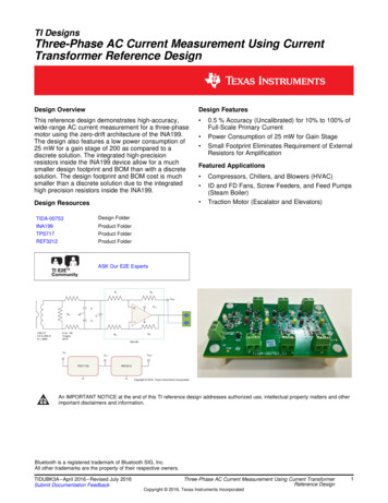
Issue date: 17th August 2002Application Notes1. The BasicsAll measuring instruments are subject to limitations. The purpose of these application notes is toexplain some of those limitations and to help the engineer maximise the many advantages of PEM’sRogowski current transducers.1.1What is a Rogowski current transducer?A Rogowski current transducer is used for measuring anelectric current. It provides an output voltage which isproportional to current (e.g. 1mV/A). It tracks the current as itchanges with time and therefore can reproduce the currentwaveform on an oscilloscope or any type of data recorder.Alternatively the output can be connected to a digital voltmeter(DVM) to give a reading of rms current.PEM produces a range of Rogowski transducers formeasuring currents from a few hundred mA's to hundreds ofkilo-amps. Each transducer comprises a Rogowski coilconnected to an electronic integrator by a co-axial cable asshown.The coil is closely wound on a thin plastic tube of circular crosssection and surrounded by insulation. It is looped around theconductor or device carrying the current to be measured. Oneend of the coil is permanently attached to the connectingcable. The other end is free and is normally inserted into asocket adjacent to the cable connection. However the free endcan be unplugged to enable the coil to be looped around theconductor. The free-end must be fully inserted into the ferruleto achieve full accuracy.The coil is flexible and therefore can be inserted betweenclosely mounted conductors or devices where access isrestricted. The loop does not need to be circular and thecurrent does not need to be centrally situated or evenly distributed within the loop.1.2How does a Rogowski current transducer work ?The voltage induced in a Rogowski coil is proportional to the rate of change of current enclosed bythe coil-loop. It is therefore necessary to integrate the coil voltage in order to produce a voltageproportional to the current.ROGOWSKICOILIC1ROIeINTEGRATOR2 Power Electronic Measurements Ltd. Sept. 2002VOUT
Issue date: 17th August 2002Application NotesThe coil is uniformly wound with N turns/m on a non-magnetic former of constant cross section area A2m . If formed into a closed loop then the voltage e induced in the coil is given by the equatione µ oNA di/dt H di/dtwhere H (Vs/A) is the coil sensitivity and I is the current to be measured passing through the loop.The loop does not need to be circular and e is independent of the current position in the loop. Toreproduce the current waveform as a measurement signal which can be displayed on an oscilloscopeor quantified using a DVM, all that is required is means for accurately integrating the coil voltage, suchthatVout 1/Ti e.dt RSH.Iwhere Ti RoC1 and Rsh H/Ti is the transducer sensitivity in (mV/A).1.3What are the advantages of Rogowski current transducers ?PEM’s Rogowski current transducersCan measure large currents without saturating. The size of the Rogowski coil requiredremains the same despite the size of current. This is unlike other current transducers whichbecome bulkier as the current magnitude increases. For currents of several kA's or more thereis really no better alternative than the Rogowski transducer!Are easy to use - the coil is thin and flexible and easy to insert around a current carryingdevice.Are non-intrusive. They draw no power from the main circuit carrying the current to bemeasured. The impedance injected into the main circuit due to the presence of the transducer isonly a few pico-Henries!Have a very wide bandwidth extending from typically 0.1Hz up to 17MHz. This enables thetransducer to measure or reproduce the waveform of very rapidly changing currents - e.g.several thousand A/µs. With the exception of co-axial shunts, which are very inconvenient touse, most other current transducers have bandwidths limited to about 100kHz.Provide an isolated measurement at ground potential similar to other current transducers(except co-axial shunts) i.e. there is no direct electrical connection to the main circuit.Can measure AC signals superimposed on large DC. The transducer does not measuredirect currents - as a result it can measure small AC currents in the presence of a large DCcomponentCan measure changes of current as fast as 40,000A/µs.1.4How does a Rogowski transducer compare to a Current Transformer ?The main feature in common with a current transformer is that a Rogowski transducer does notmeasure the direct current component, it only measures the alternating components. However unlikecurrent transformers PEM’s Rogowski current transducers.do not suffer from magnetic saturationcan take large current overloads without damage (provided the dI/dt ratings are not exceeded –see Sections 4.2 to 4.5)can measure very large currents without increase in transducer sizehave a very wide bandwidth (although this is also true for certain specialised CTs). and of course are flexible, thin, clip-around and easy to use3 Power Electronic Measurements Ltd. Sept. 2002
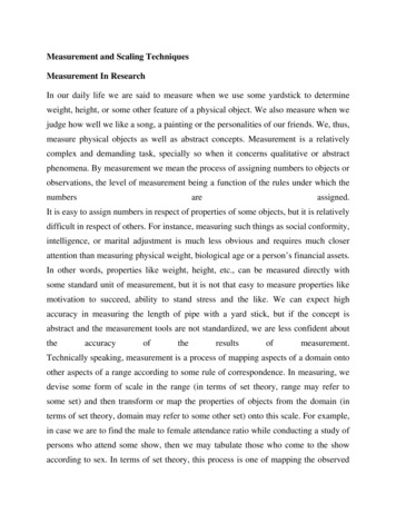
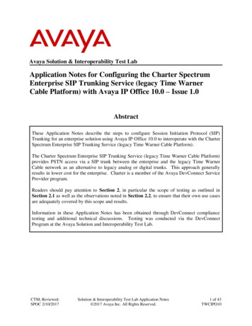
Issue date: 17th August 2002Application Notes2. Frequency Response – measuring sinusoids, quasi sinusoids and pulses2.1What is the typical frequency response of a Rogowski current transducer?Gain (mV/A) (dB)For sinusoidal currents the measurement will be within 3dB of the specified sensitivity over a range offrequencies from fL to f H which is referred to as the bandwidth, this is shown below.40 dB/ decade-60 dB/decadefLfHfrequency(log scale)To ensure that the widest possible range of currents can be measured PEM produce several types ofRogowski current transducer enabling sinusoidal, quasi-sinusoidal and pulsed currents containingfrequency components from 0.1Hz to several MHz to be monitored.2.2What determines high frequency (-3dB) bandwidth of Rogowski current transducers?The transducer behaviour at frequencies approaching and exceeding its specified (-3dB) bandwidth isvery complicated. It is related to the distributed inductance and capacitance of both the coil and theco-axial cable (which have different characteristic impedances) and their terminations, and to thegain-frequency characteristic for the op-amp IC used for the integrator. It also varies depending on theposition of the current within the loop although up to the (-3dB) bandwidth the variation is small.PEM has produced several publications regarding the high frequency behaviour of Rogowskitransducers and these can be downloaded in http://www.pemuk.com/publications.The typical (-3dB) high frequency bandwidth for each type of Rogowski transducer manufactured byPEM is listed on the relevant specification sheet. These can be downloaded inhttp://www.pemuk.com/products. The values given assume the current is centrally distributed within acircular coil loop.2.2.1 Phase shift and attenuation of sinusoidal currents from kHz to MHzFor sinusoidal current at frequencies approaching the specified bandwidth the measurement gain(mV/A) reduces and there is an increasing phase delay.PEM Ltd has a detailed computer simulation of the coil-cable-integrator system and can predict themeasurement performance for any type of pulse or waveform e.g. phase shift at a given frequency. Ifyou have questions regarding the high frequency behaviour of a particular transducer please contactus.The figure below is a simulation of the high frequency performance of a new addition to PEM’s CWTrange, the CWT6, with a 300mm coil and a 2.5m cable.4 Power Electronic Measurements Ltd. Sept. 2002
Issue date: 17th August 2002Application NotesCWT6 with a 300mm Rogowski coil and a 2.5m connecting cableGain (mV/A)0-20-40-60Phase lag (deg)0-100-200-300-4001.6MHz16MHzFrequency MHz160MHzThe dashed line shows the ideal response above the –3dB limit and is only typical since theperformance becomes more dependant on current position as the frequency increases. The 2.5mcable provides a significant proportion of the phase delay (4.5 deg per MHz).As an example the picture below and the picture on the next page show a comparison between - aCWT6 with fH(-3dB) 16MHz, a CWT6LF with fH(-3dB) 6.5MHz and a 50 MHz coaxial shunt. TheCWT6LF has a lower high frequency bandwidth and shows some slight distortion and increased delayover the CWT6.Measurement of a 2MHz damped sinusoid timebase 100ns /div – CWT6 with a 300mm coil and2.5m connecting cable versus a coaxial shunt5 Power Electronic Measurements Ltd. Sept. 2002
Issue date: 17th August 2002Application NotesMeasurement of a 2MHz damped sinusoid timebase 100ns/div – CWT6LF with a 300mm coil and2.5m connecting cable versus a coaxial shuntWhere very high frequency bandwidths are required and low frequency performance can be sacrificedPEM can produce custom designed Rogowski current transducers featuring passive integration - seehttp://www.pemuk.com/products/custom.htm.2.2.2 Measuring fast switching transients (sub µs)In practice, transducer users are unlikely to be measuring sinusoidal currents at several MHz but theycan be measuring current pulses, or current waveforms with fast switching edges, which containharmonic components extending into the MHz range. Such pulses or switching transients may suffersome distortion of shape and will have a measurement delay in the region of 20 to 200ns dependingon the transducer bandwidth and the length of connecting cable.CWT3CWT03LFMeasurement of a fast switching edge - timebase 250ns/div - 10A/div (100A/div in case of CWT3)CWT03LF with a 200mm Miniature coil and 4m connecting cableCWT3 with a 500mm coil and a 2.5m connecting coilHigh performance Current Transformer – 70MHz – 0.1V/A6 Power Electronic Measurements Ltd. Sept. 2002
Issue date: 17th August 20022.3Application NotesWhat determines the low frequency (-3dB) bandwidth of Rogowski current transducers?The integrator gain increases as frequency is reduced and in theory becomes infinite as the frequencyapproaches zero. The bandwidth of the integrator must be limited otherwise the gain at very lowfrequencies and the dc drift will be excessive. The limitation is achieved by placing a low pass filter inparallel with the integrating capacitor. The diagram below shows a simplified version of the integratorcircuit which is sufficient to explain the performance limitations.RoCOILIntegratorGain (dB)FilterNetworkC1Go maxf (Hz)(log scale)Voutf1The overall transducer gain-frequency relationship is as shown in section 2.1. The (-3dB) bandwidth fLis usually approx. 20% greater than the filter break frequency f1.Setting the low frequency (-3dB) bandwidth is a compromise between the capability of the transducer to measure small currents at low frequencyminimising the phase shift and droop maintaining a good high frequency bandwidth.2.3.1 Phase shift, small currents and low frequency noiseRogowski transducers can readily measure large currents at low frequencies or small currents at highfrequencies but they are not as suitable for measuring low currents (e.g. 10mA) at low frequencies(e.g. 50Hz). This section explains why.The integrator op-amp generates low frequency random noise (1/f noise) which is distributed aroundthe low frequency bandwidth where the integrator gain is at a maximum. The magnitude of this noiseis proportional to 1/f1H where H is the coil sensitivity. The value of 'Noise max' for each transducer islisted on the specification sheet as a peak to peak voltage. An example of low frequency noise for aCWT15 is shown on the next page where the magnitude of the predicted noise (7mVp-p) is shown bythe cursor bars on the oscilloscope trace.To minimise the noise, the low frequency bandwidth can be reduced, (i.e. fL increased), but thisresults in increased phase distortion at low frequencies. Alternatively coils with a higher value of Hcan be used but, because this increases the coil inductance, this also reduces the high frequencybandwidth of the transducer.For the majority of PEM's transducers a compromise between the values of noise max and lowfrequency bandwidth is reached such that the transducer has a small phase lead at 50Hz (typically 1to 2o).7 Power Electronic Measurements Ltd. Sept. 2002
Issue date: 17th August 2002Application NotesMeasured low frequency noise from a CWT15 transducer timebase 400ms – 2mV/divFor high sensitivity ranges of CWT (200mV/A to 20mV/A) the integrator gain is relatively high and thelow frequency bandwidth has to be reduced to keep the noise down to acceptable levels. For examplethe CWT015 with a sensitivity of 200mV/A and peak current of 30A has a fL bandwidth of 150Hz.Conversely the CWTLF range has an extended low frequency bandwidth so that it is suitable formeasuring small currents at low frequency. For example the CWT15LF has an fL 0.11Hz comparedto the CWT15 where fL 0.8Hz. To achieve this a coil with a high H value is used and the penalty is areduced high frequency bandwidth.2.3.2 Measuring long (ms to 100’s ms) pulses of current and the droop effectFor non-sinusoidal current waveforms (such as a chopped or rectified current) the effect of the phasedisplacement at low frequencies will cause some distortion of the waveform. This also applies forcurrent pulses of relatively long duration. This distortion is termed droop and the effect is shownbelow.100%actualcurrentmeasuredcurrenttτ ms% offsetThe output eventually decays exponentially to zero with a time constant T determined by the lowfrequency bandwidth of the unit. PEM define a value of droop for a rectangular pulse in %/ms for eachtransducer. The droop value for a particular unit is listed on the relevant specification sheet.The diagram below shows how the ‘% offset’ for a given pulse of time duration τ (where τ T) can becalculated given the droop value for a rectangular pulse8 Power Electronic Measurements Ltd. Sept. 2002
Issue date: 17th August 2002Application Notesgeneral waveform1/2 sine waveformpeak value 1peak valuemean value 2/πmean valuetτtτ% offset% offsetSo for the general waveform% offset τ x (mean value / peak value) x (droop in %/ms)e.g. for the ½sine waveform% offset τ x (2 / π) x (droop in %/ms)The two oscilloscope traces below show a practical comparison between measurements by - aCWT6, CWT6LF and a coaxial shunt. The shunt has no droop. The CWT6LF has a much improveddroop performance due to its lower fL 0.27Hz compared to fL 1.0Hz for the CWT6.Measurement of a capacitor discharge time 10ms/div – 100A/div – CWT6 versus a coaxial shuntMeasurement of a capacitor discharge time 10ms/div – 100A/div - CWT6LF versus a coaxial shunt9 Power Electronic Measurements Ltd. Sept. 2002
Issue date: 17th August 2002Application Notes3 Accuracy and Calibration3.1How do PEM calibrate their transducers (and to which standards)?Where the sensitivity 10mV/AThe transducers are calibrated with a 50Hz test current approximately central in the loop andperpendicular to the plane of the coil. RMS currents of 400A, 1000A, 2000A, or 4000A at 50Hz areused depending on the transducer rating. An ac current controller has been developed which keepsthe test current constant to better than 0.2%. A UKAS calibrated 4000:1 current transformer andburden resistor are used for comparison with the transducer reading. The transducer integrator gain istrimmed to give a reading within 0.2% of the specified output for the transducer.Since the integrator gain is set by high stability resistors and capacitors little change if any of thetransducer sensitivity with time is expected. Transducers that have been returned for calibration afterseveral years of use have needed less than 1% adjustment.The ac current controller was the subject of a conference paper at the 1999 European Conference onPower Electronics and can be downloaded from http://www.pemuk.com/publications.Where the sensitivity 20mV/AThe transducers are calibrated with a 2kHz test current distributed around the coil circumference (insuch a way as to approximate to a current central in the loop). RMS currents in the region of 10A to100A are used depending on the transducer rating. A precision signal generator and wide-bandwidthamplifier generate the test current. A UKAS calibrated wide-bandwidth CT is used for comparisonpurposes. The transducer integrator gain is trimmed to give a reading within 0.2% of the specifiedoutput voltage for the transducer.High Frequency performanceThe high frequency performance is checked using a 17µsec pulse of approx. amplitude 150A, 300Aor 1500A depending on the coil sensitivity. The pulse has fast rising and falling edges as shown below(with dI/dt up to 7000A/µs). The pulse is measured by the Rogowski transducer and by a 20MHzPearson CT for comparison.Timebase 4.0 µs10 Power Electronic Measurements Ltd. Sept. 2002
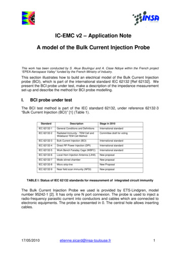
Issue date: 17th August 20023.2Application NotesLinearityLinearity error is the difference I between the true current value, I ,and the measured value Vout/ RSH(where RSH is the transducer sensitivity). For a fixed frequency and fixed current position the linearityerror will vary with the current magnitude over the rated range of the transducer.Because Rogowski current transducers contain no magnetic materials they are expected to be verylinear since there are no saturation or non-linear effects associated with the magnitude of the current.For example a test was made using a CWT30 (RSH 1.000 mV/A and a rated peak current of 6kA). A50Hz current was kept in a fixed position, central to the coil-loop, and increased in steps of 200A fromzero to its rated value. It was found that the maximum difference was 1.7A (with 3600A current) andthe maximum proportional difference was 930ppm (1.3A difference with 1400A current). The linearitywas therefore found to be better than 0.05% of full scale or 0.1% of actual reading. The linearity mayin fact be better than this since the accuracy of measuring the current was of the same order as thedifferences.O/P from a CWT30 (6000Apk) V5Proportional error (ppm) (measured value - true value) / true valueError (A) (measured value - true value)0-5-5000-3000-10000100030005000Current (A)3.3Positional AccuracyDue to small variations in the winding density and coil cross-sectional area the transducer outputvaries slightly depending on the position of the current within the coil loop. For standard coils the errorassociated with moving the conductor under test around the current loop is typically 1% of thecalibrated value, for miniature coils typically 2% of the calibrated value.The diagram below shows the variation of accuracy throughout the coil. The variation is greatest whenthe current is positioned near the junction of the connecting cable and the coil, where there is somediscontinuity, and the error here can be typically 4%. Since in most applications the current isdistributed throughout a significant part of the area contained by the coil loop the reading will be veryclose to the calibration value.POSITIONAL ACCURACY OF ASTANDARD ROGOWKSI COIL % error with a point source of currentCBATypeABCMiniatureCoil 0.5% 1% 3%StandardCoil 0.5% 1% 2%The current should not be positioned close to thecoil-cable junction (shown by the shaded area)since the error for this region is greater.11 Power Electronic Measurements Ltd. Sept. 2002
Issue date: 17th August 20023.4Application NotesThe effect of external currents and voltages external to the Rogowski loopError can also arise due to the presence of currents close to but outside the Rogowski coil loop whichideally should not provide any reading. However an external current of magnitude 100A close to theside of the coil will give a reading of up to 2A. This error will significantly decrease as the externalcurrent becomes more distant from the coil.If the external current (outside the coil loop) is much greater than the current being measured (insidethe coil loop) then the error may be significant. This is particularly relevant if the external current isflowing in a nearby multi-turn coil.Similarly if there is a surface with a high voltage very close to the coil, and the voltage is subject tohigh rates of change (e.g. several 100 V/µs) or high frequency oscillations in the MHz range, theninterference can arise due to capacitive coupling with the coil.As a check for the effect of external currents or voltages the user should place the Rogowskicoil in approximately the same position as used for measuring the desired current, but notlooped around the desired current. Ideally there should be no measured signal. If there isinterference then the same interference will be superimposed on the current waveform when itis measured and this can be taken into account when interpreting the measurement.3.5TemperatureThe overall sensitivity of Rogowski transducers varies with temperature because over the ratedtemperature range the coil sensitivity reduces with increasing temperature mainly due to expansion of the plasticformer of the coil.the passive component values which set the integrator time constant, drift slightly withtemperature.These sources of error are minimised by using a plastic former with a very low expansion coefficientand using high stability capacitors and resistors.A summary of the effect of temperature for each product type is included in the table below:Product TypeCWTCWT MiniRGFIRFRogowski coilTemperatureorange ( o(ppm/ C)-150no data-200-200IntegratorTemperatureorange ( C)Thermal coefficiento(ppm/ C)0 to 400 to 400 to 50-10 to 55 100 100 120 12012 Power Electronic Measurements Ltd. Sept. 2002
Issue date: 17th August 2002Application Notes4 What happens the current rating of the transducer is exceeded?4.1Peak CurrentThe transducers are designed to have an output of 6V for the rated peak current. If the peak currentexceeds its rating the integrator will saturate and the measured waveform will be completely corrupted(unlike an amplifier for which the output waveform is merely clipped).Exceeding the peak current rating will not damage the transducer provided the dI/dt ratingsare not exceeded. It will return to normal operation after the current surge has passed.The time it takes for the transducer to return to normal operation once the surge has passed isdependent on the low frequency bandwidth of the unit. For example the following oscilloscope tracesshow the recovery of a CWT03 and a CWT03LF from saturation. Both transducers are subjected to astep of dc current of 100A which is sufficient to cause saturation (the peak current rating is 60Acorresponding to an output voltage of 6V). The CWT03LF has an extended low frequency bandwidthfL 2.2Hz and it takes the transducer approximately 350ms to recover from saturation. The CWT03 onthe other hand has an fL 105Hz and has recovered from saturation in approximately 13ms.CWT03LF - fL 2.2Hz - Timebase 100msCWT03 - fL 105Hz - Timebase 5ms13 Power Electronic Measurements Ltd. Sept. 2002
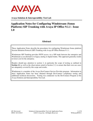
Issue date: 17th August 2002Application Notes4.2 RMS currentThere is no limit on rms current.4.3 Peak di/dtThis is the maximum di/dt above which the transducer will fail to correctly measure the current. Valuesare given on the specification sheet.4.4 Absolute maximum di/dt (peak)The transducer can be damaged by excessive dI/dt due to the voltage generated in the coil. Thespecification sheet gives an absolute maximum rating for dI/dt for each transducer that must not beexceeded.4.5 Absolute maximum di/dt (rms)The transducer can also be damaged by sufficiently high repetitive dI/dt even though the peak dI/dtrating is not exceeded. A damping resistor is used to provide correct termination of the Rogowski coiland cable to prevent reflections (seen as high frequency damped oscillations) appearing on themeasured waveform. A high repetitive di/dt will cause excessive power to be dissipated in thisresistor.For sinusoidal waveforms the calculation of rms di/dt is straight-forward,di/dt rms 2πfIrms (where f is the measured frequency and I rms the rms value of the measured current)For pulsed waveforms an example of how to calculate the di/dt rms is shown below,I5000A0t(us)125 2650(a)dI/dt5000A/ust0-5000A/us(b)Consider the current waveform shown in Figure (a) with a repetition frequency of 20kHz. Figure (b)shows the corresponding dI/dt waveform.The rms dI/dt is given by 5000 A/µs x (1µs/25µs)0.5 1 kA/µs rms.Where very high di/dt ratings are required and low frequency performance can be sacrificed PEM canproduce custom designed Rogowski current transducers with passive integration (see Products).14 Power Electronic Measurements Ltd. Sept. 2002
Issue date: 17th August 2002Application Notes5 Output loading and cablingWith the exception of the IRF range of Rogowski transducers the minimum input impedance for anymeasuring device (oscilloscope, DVM, power recorder etc.) connected to the transducer must be100kΩ or greater for rated accuracy.The IRF requires an input impedance of at least 10kΩ for rated accuracy. The IRF is designed forpermanent installation into equipment and the lower input impedance allows it to interface with a widerange of data acquisition equipment.The output impedance of all PEM’s Rogowski current transducers is approximately 50Ω. Any cablesused to connect the output of the transducer to the data acquisition device, longer than the 0.5m coaxial cable supplied with the unit, should be 50Ω singly screened coaxial cable. Although at presentcables longer than 0.5m have not been included in the immunity tests and may decrease RF noiseimmunity, PEM does not consider the use of extension cables to be problematic from the noiseviewpoint. PEM has conducted tests using a 25m extension and no discernible attenuation ofmeasured current signal has occurred although, as is to be expected, there is an increasedmeasurement delay of 5ns/m.PEM’s Rogowski current transducers cannot be terminated into a 50ΩΩ impedance. Theintegrator op-amp has insufficient output current capacity to drive a 50Ω load.15 Power Electronic Measurements Ltd. Sept. 2002
Issue date: 17th August 2002Application Notes6 How do PEM rate the voltage insulation of their Rogowski coils?The CWT and RGF ranges of Rogowski current transducers are intended for instrumentation use andnot for permanent installation on equipment. The peak voltage insulation ratings for these transducersreflect the fact the transducers are not to be used continuously at high voltages.Every Rogowski coil supplied by PEM is given a peak voltage insulation rating. The rating is derivedfrom the following test:The coil is exposed to an ac test voltage (kV) (2 x Peak voltage rating 1) / 2 (kV), for 60seconds at 50Hz. So for example a 5kV peak insulated coil will be flash tested at 8kVrms (11kVpeak), 50Hz, for 1 minute.The user should visually inspect the Rogowski coil and cable for insulation damage each time thetransducer is used. Every Rogowski coil has at least two layers of insulation covering the winding.These are always different colours making visual inspection of the integrity of the insulation easier.It is imperative that the user grounds the BNC connector from a safety viewpoint so that in the eventof an insulation breakdown at the coil (due to exceeding the voltage rating or due to mechanicaldamage), a fault current path exists via the co-axial cables to the grounded BNC connector.The practice of “floating the oscilloscope” which results in the BNC connections being isolated fromground is strongly deprecated.6.1What advice do PEM have for customers using Rogowksi coils continuously at highvoltage?As for the majority of plastics the material used for insulating PEM’s Rogowski coils can be damagedby exposure to corona over a reasonably long period of time.The Rogowski coils for CWT’s and RGF’s have been designed for intermittent use at voltages nogreater than the peak voltage to ground specified by PEM. For these conditions the effects of coronaare small and the degradation of coil insulation is negligible. Furthermore the coil can and should beinspected for damage to the insulation each time it is used.The IRF has been designed for permanent installation and hence continuous exposure to nearbyvoltages. For voltages to ground of less than 3kV peak (i.e. 2kVrms for a sinusoidal voltage), coronaeffects will be negligible, and continuous operation is permit
Can measure changes of current as fast as 40,000A/µs . 1.4 How does a Rogowski transducer compare to a Current Transformer ? The main feature in common with a current transformer is that a Rogowski transducer does not measure the direct current component, it