Transcription
1Series ET, T & VT Tiny TimACTUATORS3/4" and 1-1/8" boreSingle and double rod end stylesFPM seals optional for higher temperaturesTechnical featuresMedium:Compressed air, filtered, lubricatedor non-lubricatedOperation:Single or double actingOperating Pressure:150 PSI (10 bar)Operating Temperature:-20 to 200 F (-29 to 107 C)Cylinder Diameters:3/4", 1-1/8"Options selector for T, VT, and ETSingle Rod End ModelsQuad ring piston seal, block – vee rod sealBlock-vee piston and rod sealsEcology piston seals and block-vee rod sealDouble Rod End ModelsQuad ring piston, block – v-rod sealBlock-vee piston and rod sealsEcology piston seals and block-vee rod sealMounting StylesFlush mountClevis mountNose mountRear flange mountFront flange mountNo mountRod CFRNMSpecify5/16" or 3/8"Specify3/4" or 1-1/8"Stroke (inches)Notes: Cylinder requires a stop tube equivalentto the stroke length.Cushions not avilable on spring end of cylinder.Standard spring forces for SR and SC 3.5 lbs relaxed,11.5 lbs compressedDifferences between Series Tand Series VT air actuatorsSeries T contains a Quad RingNitrile piston seal. The VT Seriesutilizes a dual Block-Vee nitrilepiston seal design.The Block-Vee seals increase theenvelope dimensions of the SeriesVT cylinders by 3/8". All otherfeatures of the Series T and VT arethe same.Series VT cylinders have aslightly lower breakaway pressure(psig) than the Series T Tiny Timair cylinders.VT SR - 3/8 - 1.125 x 5.000 - RC - PSOptionsStroke adjustment single piston(specify adjustment length)Stroke adjustment double piston (specifyadjustment length)Cap end cushion* Non-standard port location (Specify location)Non thread rod**Magnetic PistonRod end cushionBoth ends cushionedRod extension over standard. (Specify length)Stainless steel tie rods and nutsSpring on cap end (spring extends rod)Spring on rod end (spring retracts rod)Chrome-plated stainless steel piston rodRod thread extension over standard(specify length)Stainless Steel TubeFPM seals-20 to 400 F temperature SSCSRSSTX(–)TSV* Designate head position first, and cap position last** PS option adds 1/2" to overall cylinder lengthNotes: Available on 1-1/8" bore cylinders only.1/4" effective cushion length.Add 9/16" to overall length of cylinder for each cushion.Cushion not available on spring end ofa single acting cylinder.ACT-58For further information www.norgren.com
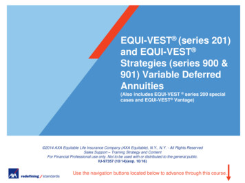
1Series T, VT, ET Tiny TimNon-NFPA InterchangeableSeries T uses Quad Ring Buna-Ring piston seal.12ACTUATORSSeries T741 Heads and Caps: Anodised Aluminum or black oxided steel.2 Rod Bushing: Oil-filled, sintered iron bushing.3 Rod Seal: Replaceable block-vee Nitrile rod seal (FPM optional).4 Piston Rod: Hard chrome plated high tensile steel piston rod.5 Seals: O-ring type seals.6 Tie Rods: High yield strength tie rods.7 Piston Seal: Replaceable quad ring Nitrile (FPM optional).8 Piston: Machined alloy.9 Tubing: Hard anodised I.D. aluminum tubing.3586910Series VT10 Series VT uses Block-Vee Nitrile piston seal. This increasesenvelope dimension by 3/8" but provides lower breakaway pressure.Series ETSeries ET actuators achieve their cushion effect through the normalcompression of the Buna-N “shock-absorber"seals at the completion ofthe cylinder stroke. This compressive action absorbs the cylinder’s kineticenergy and reduces the shock created by the piston striking the end caps.12The measurable cushion effect of the “shock-absorber" seals providesa predictable pounds stoppable/piston speed ratio, allowing you todetermine the exact weight that can be stopped at a given piston speed.Series ET actuators also help meet OSHA’s noise and clean airstandards. They are guaranteed to operate without lubrication for oneyear regardless of cycles. Non-lubricated operation is achieved by thecombined efforts of an oil-impregnated sintered iron piston rod busingthat lubricates the rod during normal operation, and through the use of areinforced PTFE wear ring on the center perimeter of the piston. This ringreduces friction between the piston and the cylinder tube.11 Wear Ring: PTFE reinforced wear ring.1112 Impact Dampening Seals: Specifically designed pistonincorporates energy absorbing seals to dissipate the forces generatedduring impact without increasing envelope dimensions. Not availablefor cylinders with oversize rods. Not recommended for applications thatrequire 100% repeatable stroke increments, or for applications thatexceed the pounds stoppable.Effect of Impact Dampening Seals on Total Stroke of CylindersPSIEnergy Absorption Capacity of Impact Dampening SealsIn./Lbs ofKinetic EnergySizeAbsorbable3/4"1.51-1/8" 3Pounds* Stoppable at Following Speeds612in/secin/sec32.48.079.216*Pounds must include piston and rod assembly weightFor further information 1160in/sec.23.59020406080100Cylinder Bore3/41-1/16 020.17.12.08.05.020The figure above represents total stroke loss (both ends) for the pressure indicatedfor new cylinders. The impact dampening seals will take some compression setduring operation of the cylinder and the stroke loss will decrease. To determinestroke loss for either head or cap divide the value shown by 2.ACT-59
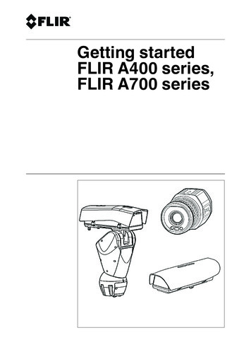
1Series T, ET, VT (3/4" Bore, 5/16" Rod)ACTUATORSFlush Mount – TF, VTF, ETFStandard Cylinder – TNM, VTNM, ETNM4.63 (16)T Stroke1 (25) sq.4.25 (6)133.75 (19).25 (6)1/8 NPT.44 (11)5/16 – 182.13 (3).75 (19).25 (6).5 (13)Front Flange Mount – TFR, VTFR, ETFR312.19 (5)Drilled & C'Bored for #10 Soc. Hd. ScrewY Stroke412(51)1 (25)W Stroke.81 (21)1 (25)2.38 (10)4.25 (6).38 (10)3/4–16.44 (11)1/4 Ream.13 (3)Head Trunnion Mount* – THT, VTHT, ETHT .000Dia. .499 - .002.63 (16)1/8" Max.Radius.75(19)R.38 (10)1.31 (8)32Back Trunnion Mount* – TBT, VTBT, ETBT1/8" Max.Radius1.5 (38)3X Stroke1.75(19)1.5(38)Clevis Mount – TC, VTC, ETCNose Mount – TSR, VTSR, ETSR41.31 (8).31 (8)22.25 (6)Drilled & C'Bored for #6 Soc. Hd. Screw1.5(38)3V Stroke.69 (18).25 (6)2 (51)U StrokeRear Flange Mount – TFC, VTFC, ETFCDrilled & C'Bored for #10 Soc. Hd. ScrewZ Stroke4.56(14)T StrokeS Stroke.75 (19).75(19) .000Dia. .499 - .0021.5 (38).75(19)*Configured as special at factoryRSTUVWXYZSeries TQuad ring seals.44 (11)2.81 (71)1.81 (46)1.94 (49)1.38 (35)2.63 (67)2.56 (65)2.5 (64)2.38 (60)Series VT Block vee sealsSeries ET Ecology seals.44 (11)3.19 (81)2.19 (56)2.31 (59)1.75 (45)3 (76)2.94 (75)2.88 (73)2.75 (70)NOTE: For spring return cylinders add an additional stroke length to dimensions.Dimensions in inches (mm)ACT-60For further information www.norgren.com
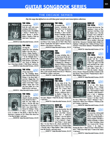
1Series T, ET, VT (1-1/8" Bore,5/16" & 3/8" Rods)41.38 (35) sq.U StrokeT StrokeB4.25 (6).75(19)dia.31.63(16)A21/8 NPT.25 (6).13 (3).75 (19).5 (13)Front Flange Mount – TFR, VTFR, ETFR.25 (6).88 (22)2.25 (6).25 (6)Drilled & C'Bored for #10 Soc. Hd. ScrewRear Flange Mount –TFC, VTFC, ETFCDrilled & C'Bored for #10 Socket ScrewZ Stroke4V Stroke13CDrilled & C'Boredfor #10 Socket ScrewY Stroke.25 (6)1.88(48)2.38 (61)2.38(61).31 (8)1.38 (35)Nose Mount – TSR, VTSR, ETSR31.38 (35)2Clevis Mount – TC, VTC, ETCW Stroke41.88(48).31 (8)2X Stroke.44 (11).81 (21)4.38 (10).5(13)134113ACTUATORSFlush Mount – TF, VTF, ETFStandard Cylinder – TNM, VTNM, ETNM1.31 (8)33/4–16.44(11)2ABCPiston Rod5/16 Diameter5/16-18.63 (16).25 (6)3/8* Diameter3/8-24.75 (19).31 (8)* 3/8" dia. piston rod will be furnished asan option only if specified.RSTUVWXYZ.13 (3)1/4 ReamSeries TQuad ring seals.44 (11)2.81 (71)1.81 (46)1.94 (49)1.31 (33)2.63 (67)2.63 (67)2.5 (64)2.38 (60)Series VT Block vee sealsSeries ET Ecology seals.44 (11)3.19 (81)2.19 (56)2.31 (59)1.69(43)3 (76)3 (76)2.88 (73)2.75 (70).81 (21)2NOTE: Series T, ET & VT 1-1/8" BoreCylinders are available with adjustablecushions. Increase dimensions Tthrough Z by 9/16" for one cushionand by 1-1/8" for both endscushioned. (See “Ordering Procedure"for details.) For spring return cylindersadd an additional stroke length toabove dimensions.Dimensions in inches (mm)For further information www.norgren.comACT-61
1Series DT, EDT, VDT (Double Rod End)ACTUATORS3/4 Bore1-1/8 BoreStandard Cylinder (DTNM, VDTNM, EDTNM)Standard Cylinder (DTNM, VDTNM, EDTNM)431 (25)W Stroke1.75(19)dia.1(25)2.75 (19).13 (3)3.25 (6)1/8 NPT.44 (11).44 (11).25 (6).63(16)Stroke.75 (19).13 (3).56 (14)2(51)21/8 NPT.25 (6).75 (19).75 (19).13 (3).63 (16).19 (5)Y StrokeX Stroke.25 (6)1.38 (35).38 (10) StrokeA.63 (16) StrokeDrilled & C'Boredfor #10 SocketScrew (4 Holes).25 (6).25 (6.4)Y Stroke.38 (10) Stroke1.88(48).31 (8)Drilled & C'Boredfor #10 Socket Screw.31 (8)Nose Mount – DTSR, VDTSR, EDTSRNose Mount – DTSR, VDTSR, EDTSR3/4-16.13 (3)Front Flange – DTFR, VDTFR, EDTFR2.38(61)W Stroke.25 (6).88(22)1.5(38).81 (21)B1C.56 (14) StrokeFront Flange – DTFR, VDTFR, EDTFR.25 (6)Stroke.75(19)dia.69(18)Drilled & C'Boredfor #10 Soc. Hd. ScrewW StrokeFlush Mount – DTF, VDTF, EDTFX Stroke.19 (5)41.38(35)AFlush Mount – DTF, VDTF, EDTFDrilled & C'Boredfor #6 Soc. Hd.Screw (4 Holes)1.38(35).38 (10) Stroke.81 (21)W Stroke.38 (10) Stroke.13 (3).56 (14)3/4-16.13 (3).56 (14)*Configured as special at factoryABCPiston Rod5/16 Diameter5/16-18.63 (16).25 (6)3/8* Diameter3/8-24.75 (19).31 (8)* 3/8" dia. piston rod will be furnishedas an option only if specified.SWXY3/4" BoreDT2.81 (71)2.06 (52)1.69 (43)2.38 (60)VDT & EDT3.19 (81)2.44 (62)2.06 (52)2.75 (70)1-1/8" BoreDT2.81 (71)2.06 (52)1.56 (40)2.38 (60)VDT & EDT3.19 (81)2.44 (62)1.94 (49)2.75 (70)NOTE: Series DT, VDT & EDT1-1/8" bore cylinders are availablewith adjustable cushions. Increasedimensions S through Y by 9/16" forone cushion and by 1-1/8 for bothends cushioned.Dimensions in inches (mm)ACT-62For further information www.norgren.com
1Series T, ET, VT Mounting AccessoriesRod Clevis (includes pin).25 (6)Ream.25 (6).31 (8)1.31(33)ACTUATORSPin (includes snap rings).75 (19)dia.68(17)1.56(40).75 (19).94 (24)APart Number4003540036Part Number49085Thread5/16-183/8-24Rod EyeMounting Screw (for TF, VTF, ETF 3/4").25 (6)Ream.75 (19)dia.1.31(33)1.56(40).31 (8).68(17)1.25(32)6-32 Th'dAPart Number4004240043Part Number51043Thread5/16-183/8-24Clevis Bracket (includes pin)Mounting Nut (for TSR, VTSR, ETSR)010.75 (19)dia.1.12(28).31 (8).88 1.12(28).38 (22)(19).72(18)1.26 (32).42(11)1.03(26) sq.#8 C-Bore1.37 (35) sq.Part Number40038Part Number52010Rod Aligners (includes jam nut)2 AngularMisalignment1.25 (32)1/16" 1 (25)1.38 (35)2.13 (54).5 (13).75 (19).16 (4)Rod AlignersRA-31C5/16-181 (25.4)1.38 (35)2.13 (54).5 (13).75 (19).19 (5)RA-325/16-241 (25)1.38 (35)2.13 (54).5 (13).75 (19).19 (5)RA-383/8-241 (25)1.38 (35)2.13 (54).5 (13).75 (19).22 (6)Dimensions in inches (mm)For further information www.norgren.comACT-63
1NFPA Interchangeable Tiny TimTA, TAV, TAE ActuatorsACTUATORS3/4", 1", and 1-1/8" boreSingle and double rod end stylesRated 150 psi air-20 to 200 F (-29 to 107 C) operating temperaturesFPM seals optional for higher temperaturesDesigned to conform with NFPA (T3.6.11) 1972.Technical dataMedium:Compressed air, filtered, lubricatedor non-lubricatedOperation:Double actingOperating Pressure:150 PSI (10 bar)Options selector for TA, TAV,and TAEOperating Temperature:-20 to 200 F (-29 to 107 C)Cylinder Diameters:Nominal Inch: 3/4", 1", 1-1/8"TA 6 - 3 A - 1.125 x 5.000 -D- PS - SSSingle Rod End ModelsSubstituteQuad ring piston seal, block – veeTArod sealBlock-vee piston and rod sealsTAVEcology piston seals and block-veeTAErod sealDouble Rod End ModelsQuad ring piston, block – v-rod sealDTABlock-vee piston and rod sealsDTAVEcology piston seals and block-veeDTAErod sealMounting StylesSubstituteSide Tapped1Side through holes2Cap eye4Head male rabbet5Threaded nose6Cap rectangular flange7Head flange8Head flange (no pilot)9Rod DiameterSubstitute1/4"15/16"23/8"31/2"4Note: 1/2" diameter rods are not availableon Series TAERod End Thread Style(Specify “A" or “B" on all models)Rod SizePRThd A1/4 øNo Thread1/4-285/16 øNo Thread5/16-243/8 øNo Thread3/8-241/2 øNo Thread1/2-20OptionsSubstituteStroke adjustment single pistonA(-)(specify adjustment length)Stroke adjustment double pistonAA(-)(specify adjustment length)Port location (other than standard)*L(-)Magnetic piston*PSRod extension (specify length)RX(-)Stainless steel tie rods &nutsSPiston Rod (chrome plated stainless steel)SSSpecial Rod thread(specify length)T(-)Stainless Steel TubeTSRod thread extension (specify length)TX(-)FPM sealsVSingle Acting ActuatorsSpring on Rod EndSRSpring on Cap EndSCSubstituteAdjustable Cushions**Rod end onlyDRCap end onlyDCBoth endsDStroke (inches)0.125 - 48.000BoreSubstitute3/4"0.751"1.001-1/8"1.125Thd B10-321/4-285/16-247/16-20* Specify head position first followed by cap positionPS option adds 1/2" to overall length.** Add 1/2" per cushioned end to overallcylinder length.Effect of Impact Dampening Seals on Total Stroke of CylindersPSI020406080100Cylinder Bore3/41-1/16 020.17.12.08.05.020The figure above represents total stroke loss (both ends) for the pressure indicatedfor new cylinders. The impact dampening seals will take some compression setduring operation of the cylinder and the stroke loss will decrease. To determinestroke loss for either head or cap divide the value shown by 2.ACT-64Energy Absorption Capacity of Impact Dampening SealsIn./Lbs ofKinetic EnergySizeAbsorbable3/4"1.51-1/8" 3Pounds* Stoppable at Following /sec.81.848in/sec.41160in/sec.23.59*Pounds must include piston and rod assembly weightFor further information www.norgren.com
1Series TA NFPA Interchangeable Tiny TimRM (Dia.)1/8 NPTCC (Thread).25 (6)142.63 (16).5 (13).25 (6).75 (19)3.13 (3)TN.25 (6)SN Stroke1.75 (45) Stroke2.13 (54) StrokeBoreBCCCDDBDNEEWKMNNTRRMRM1RTSDSNTFTNUFEED (Flat)NT (Thread)(2 in head, 1 in cap)Style 3 – (MNR1) Threaded Male Rabbet*RM1 .000–.0031/8 NPT(Dia.)CC (Thread)KM (Thread)1.25 (6)4.25(6).5 (13).75 (19)2.63 (16)3.13 (3)E.63 (16)1.75 (45) Stroke2.63 (67) Stroke3/41.06 (27)1/4-28.22 (6)8-32.63 (16)1 (25).25 (6)5/8-18.75 (19)8-32 x 3/16 DP.5 (13).63 (16).69 (18)8-32 x 1/4 DP1.31 (33)1.31 (33)1.5 (38).63 (16)2 (51)1*1.41 (36)5/16-24.25 (6)10-32.88 (22)1.38 (35).38 (10)3/4-161 (25)10-32 x 1/4 DP.88 (22).75 (19).81 (21)8-32 x 1/4 DP1.25 (32)1.25 (32)1.88 (48).88 (22)2.38 (60)RM .000–.003Style 2 – (MS8) Side Through Holes(not available w/oversized rod)D (Flat)RM (Dia.)1/8 NPT*Configured as special at factoryCC (Thread).25 (6)CC (Thread).25 (6).5 (13)4.25 (6).5 (13)1.75 (19).63 (16)2BC3.13 (3)N1.75 (45) Stroke2.13 (54) Stroke.25 (6)E21DNRT (Thread)(4 Holes)(Dia.)3.63 (16).25 (6)1.75 (45) Stroke2.13 (54) StrokeEDB (Three holes forSockethead Capscrew)Style 4 – (MP3) Cap EyeD (Flat)CC (Thread)ED (Flat)RM (Dia.).89 (23) Dia.1/4 Dia.1/8 NPT41CC (Thread).25 (6).25 (6).5 (13)1.75 (19)3.13 (3)E1.75 (45) Stroke2.38 (60) Stroke1/8 NPTD (Flat).13 (3)1.75 (45) Stroke2.38 (61) Stroke.63 (16).25 (6)EEW1.5 (13).75 (19).25 (6)1.75 (45) Stroke.63 (16).63 (16)23E2.63 (67) StrokeED (Flat)Style 8 – (MF1) Head Flange23ECC (Thread)KM (Thread)414.75 (19).75(19)Style 6 – (MN1) Threaded Nose.218 (5) Dia (4 Holes).25 (6)E.44 (11)TFCC (Thread)2.31 (8).5 (13)UF1/8 NPT32.88 (73) StrokeR EStyle 9 – (MF7) Head Flange (No pilot).5 (13).25 (6).75 (19)1.75 (45) Stroke2.63 (16).25(6).13 (3)4.25 (6).63(16).218 (5) Dia (4 Holes)RM (Dia.)E4 D (Flat).13 (3).75 (19)SD StrokeStyle 7 – (MF2) Cap Rectangular Flange1/8 NPT1-1/81.59 (40)3/8-24.31 (8)10-321 (25)1.5 (38).38 (10)3/4-161.13 (29)10-32 x 1/4 DP1 (25).75 (19).81 (21)10-32 x 1/4 DP1.25 (32)1.25 (32)2 (51)1 (25)2.5 (64)* Piston Dia. of 1" cylinders is 1-1/8" diameter.EStyle 5 – (MR1) Head Male Rabbet1/8 NPTACTUATORSStyle 1 – (MS9) Side TappedR E1/8 NPT .000–.003RM(Dia.)CC (Thread).25 (6)UF.5 (13)14D (Flat)TF.218 (5) Dia (4 Holes).25 (6).75 (19)1.75 (45) Stroke2.38 (61) Stroke.63 (16).25 (6).13 (3)2R E3 D (Flat)ETFUFDimensions in inches (mm)For further information www.norgren.comACT-65
1TAE, TAV NFPA Interchangeable Tiny TimACTUATORSStyle 1 – (MS9) Side TappedCC (Thread)RM (Dia.)1/8 NPTE1.25 (6)42.63 (16).5 (13).25 (6).75 (19)3 D (Flat).13 (3)TN.25 (6)SN Stroke2.25 (57) Stroke2.63 (67) StrokeENT (Thread)(2 in head, 1 in cap)Style 2 – (MS8) Side Through Holes (not availablew/oversized rod)RM (Dia.)1/8 NPTCC (Thread).25 (6)21DN3.63 (16).5 (13).25 (6).75 (19)4.13 (3)E.25 (6)SD Stroke2.25 (57) Stroke2.63 (67) StrokeED (Flat)1/8 NPTRM(Dia.)CC (Thread)D (Flat)1/8 NPTRM (Dia.)1.25 (6).5 (13).13 (3)4.25(6).75 (19)2.63 (16)3AME.13 (3)2.25 (57) StrokeZG Stroke.25.63 (16) (6)CC (Thread)KM (Thread)RMCC (Thread).25 (6).25 (6).5 (13).75 (19).63 (16).13 (3).5 (13)231/8 NPT.25 (6).5 (13).75 (19)2.25 (57) Stroke2.88 (73) Stroke.63 (16).13 (3)EEEWETFUF.75 (19).25 (6)AM2E3 D (Flat).63 (16)ERM (Dia.).218 (5) Dia (4 Holes)1CC (Thread)4.25 (6).75 (19)23.63 (16).25 (6)ETF.13 (3)R ED (Flat)UFStyle 9 – (MF7) Head Flange (No pilot).218 (5) Dia (4 Holes)1/8 NPT23142.25 (57) Stroke2.88 (73) Stroke14.25 (6)CC (Thread).25 (6)D (Flat).218 (5) Dia (4 Holes)CC (Thread).25 (6)2.44 (11).75(19)Style 8 – (MF1) Head FlangeE.5 (13)RM (Dia.)KM (Thread)2.25 (57) StrokeZG StrokeStyle 7 – (MF2) Cap Rectangular Flange1/8 NPT3.31 (8).25 (6.)1NE2.25 (57) Stroke2.63 (67) Stroke.25 (6).75 (19).5 (13)2.25 (57) Stroke1/8 NPTD (Flat)4BC4Style 6 – (MN1) Threaded NoseRT (Thread)(4 Holes)(Dia.)57/64 Dia.3.38 (86) StrokeStyle 5 – (MR1) Head Male Rabbet1/8 NPTCD1E*Configured as special at factory .000–.0031-1/8.88 (22)1.59 (40)3/8-24.38 (10).31 (8)10-321 (25)1.5 (38).38 (10)1-141.13 (29)10-32 x 1/4 DP1 (25).75 (19)1.06 (27)10-32 x 1/4 DP1.75 (45)1.75 (45)2 (51)1 (25)2.5 (64)3.38 (86)Style 4 – (MP3) Cap EyeDB (Three holes forSockethead Capscrew)Style 3 – (MNR1) Threaded Male Rabbet* .0001 –.003Bore3/41*AM.63 (16).63 (16)BC1.06 (27)1.41 (36)CC1/4-285/16-24CD.25 (6).38 (10)D.22 (6).25 (6)DB8-3210-32DN.63 (16).88 (22)E1 (25)1.38 (35)EW.25 (6).38 (10)KM5/8-183/4-16N.75 (19)1 (25)NT8-32 x 3/16 DP10-32 x 1/4 DPR.5 (13).88 (22)RM.63 (16).75 (19)RM1.69 (18).81 (21)RT8-32 x 1/4 DP8-32 x 1/4 DPSD1.81 (46)1.75 (45)SN1.81 (46)1.75 (45)TF1.5 (38)1.88 (48)TN.63 (16).88 (22)UF2 (51)2.38 (60)ZG3.13 (79)3.13 (79)* Piston Dia. of 1" cylinders is 1-1/8" diameter.CC (Thread)R E.25 (6)D (Flat).5 (13)124.13 (3).75 (19)2.25 (57) Stroke2.63 (68) Stroke.63 (16).25 (6)3ETFUFR ED (Flat)Dimensions in inches (mm)ACT-66For further information www.norgren.com
1Series DTA, DTAV, DTAE (1-1/8"Bore, 5/16" and 3/8" Rods) Tiny TimCC (Thread)ERM (Dia.)1/8 NPT1.25 (6)E(2 Holes).63 (16).13 (3).63 (16).25 (6)(1 Hole).75 (19)D (Flat).75 (19).13 (3)423TNNT (thread).25 (6)SN StrokeLB StrokeZB 2X StrokeStyle 2 – (MS8) Side Through Holes(Not available with oversize rod)DB (Four holes forSockethead Capscrew)CC (Thread)ERM (Dia.)1/8 NPTDN1.25 (6).63 (16).63 (16).25 (6).75(19).25 (6).75 (19).38(10)423 D (Flat).13 ZRZT1.38 (35).63 (16)1.75 (45)1.06 (27)1/4-28.22 (6)8-32.63 (16)1 (25)5/8-182 (51) 2.5 (64).75 (19)8-32 x 3/16 DP.5 (13).63 (16).69 (18)8-32 x 1/4 DP2.06 (52) 2.56 (65).56 (40) 2.06 (52)1.5 (38).63 (16)2 (51)2.75 (70) 3.25 (83)3.25 (83) 3.75 (95)3 (76) 3.5 (89)1*DTADTAEDTAV1-1/8DTAD TAEDTAV1.75 (45).63 (16)2.13 (54)1.41 (36)5/16-24.25 (6)10-32.88 (22)1.38 (35)3/4-162 (51) 2.5 (64)1 (25)10-32 x 1/4 DP.88 (22).75 (19).81 (21)8-32 x 1/4 DP2 (51) 2.5 (64)1.5 (38) 2 (51)1.88 (48).88 (22)2.38 (60)2.75 (70) 3.25 (83)3.25 (83) 3.75 (95)3 (76) 3.5 (89)DTAEDTAV1.88 (48).63 (16) .88 (23)2.25 (57)1.59 (40)3/8-24.31 (8)10-321 (25)1.5 (38)3/4-16 1-142 (51) 2.5 (64)1.13 (29)10-32 x 1/4 DP1 (25).75 (19).81 (21) 1.06 (27)8-32 x 1/4 DP2 (51) 2.5 (64)1.5 (38) 2 (51)2 (51)1 (25)2.5 (64)2.75 (70) 3.25 (83)3.25 (83) 4.0 (101)3 (76) 3.5 (89)* Piston Dia. of 1" cylinders is 1-1/8" diameter.ASD Stroke.5 (13)EBoreSeriesACTUATORSStyle 1 – (MS9) Side TappedBLB StrokeZB 2X StrokeStyle 3 – (MNR1) Threaded Male Rabbet*RM1 (Dia.)1/8 NPTCC (Thread)KM (Thread).25 (6).63 (16).13 (3)14.75 (19) .25 (6).13 (3)LB StrokeAMZR 2X Stroke.75 (19)2Style 5 – (MR1) Head Male RabbetECC (Thread)3 D (Flat).63 (16).25 (6)Style 6 – (MN1) Threaded Nose1/8 NPTKM (Thread)CC (Thread).25 (6).63 (16).13 (3).75 (19).75 (19)AM2EStyle 8 – (MF1) Head FlangeCC (Thread).25 (6).13 (3).13 (3).75 (19).75 (19)LB StrokeZB 2X Stroke.63 (16).25 (6)3 D (Flat)ED (Flat)UFRM (Dia.)1/8 NPTTFE.25 (6)RE.63 (16).13 (3.2)2EUFTFECC Thread.75 (19)4BC3 D (Flat).63 (16).25 (6.4)1/8 NPT.75 (19)LB StrokeZB 2X StrokeStyle 9 – (MF7) Head Flange (No pilot)RM (Dia.).63 (16).25 (6)14LB StrokeZR 2X StrokeE.63 (16).13 (3)N1E*Configured as special at factoryRM (Dia.)RT (Thread)(4 Holes)RM (Dia.)1/8 NPTRE.63 (16).25 (6.4).13 (3).75 (19).75 (19)LB StrokeZT 2X Stroke.63 (16).13 (3)D (Flat).218 (5) Dia. (4 Holes).218 (5) Dia. (4 Holes)Dimensions in inches (mm)For further information www.norgren.comACT-67
1NFPA Interchangeable Tiny TimMounts for Series TA, TAV, TAEACTUATORSPivot PinCDCLCPCyl.Bore3/41, 1-1/81, D.25 (6).25 (6).38 (10)CL.75 (19).88 (22).88 (22)CP.94 (24)1.06 (27)1.06 (27)Cyl.Bore3/41&1-1/8Cyl.SeriesTA, TAV-TAETATAV-TAEPartNo.490694907049071CD.25 (6).25 (6).38 (10)CB.25 (6).38 (10).38 , yl.SeriesTA, sTA, 8349084CB.25 (6).38 (10).38 (10).38 (10).38 (10)Eye Bracket1.25 (32).31 (8)ECBR.5 (13)ECD (dia.)E1 (25)1.38 (35)1.38 (35)R.75 (19)1 (25)1 (25)DB (Four Holes ForSockethead Capscrew)Clevis Bracket (includes pin)FLCBECBR.5(13).5(13)EE1 (25)1.38 (35)1.38 (35)R.75 (19)1 (25)1 (25)FL1.19 (30)1.25 (32)1.25 (32)CB.25 (6).38 (10).38 (10)CD.25 (6).25 (6).38 (10)DB6-3210-3210-32CD (dia.)DB (Four Holes ForSockethead Capscrew)Rod EyeCBCD (dia.)CB.44 (11).44 (11)(Full Thread)J1-1/81 (25)dia.CC (Thread)1CD.25 (6).25 (6).38 (10).25 (6).38 (10)CB.25 (6).38 (10).38 (10).38 (10).38 (10)I.5 (13).75 (19).75 (19).75 (19).75 (19)J.31 (8).44 (11).44 (11).44 (11).44 (11)Rod Clevis (includes pin)G (dia.)CBCD (dia.).13 (3)CC (Thread)CBCyl.Bore3/4.5 (13)1K1-1/8CD.25 (6).25 (6).38 (10).25 (6).38 (10)F.44 (11).56 (14).56 (14).56 (14).56 (14)G.75 (19).88 (22).88 (22).88 (22).88 (22)K.19 (5).25 (6).25 (6).25 (6).25 (6)CC1/4-285/16-245/16-243/8-243/8-24F (dia.)Dimensions in inches (mm)ACT-68For further information www.norgren.com
1NFPA Interchageable Tiny Tim Rod Alignerfor Series TA, TAV, TAE2 AngularMisalignmentCC(Th'd)1.25 (32)1/16" 38RA-44RA-50A1 (25)1 (25)1 (25)1.5 (38)1.5 (38)B1.38 (35)1.38 (35)1.38 (35)1.78 (45)1.78 (45)C2.13 (54)2.13 (54)2.13 (54)3 (76)3 (76)D.5 (13).5 (13).5 (13).69 (18).69 (18)E.75 (19).75 (19).75 (19)1.22 (31)1.22 (31)F.16 (4).19 (5).19 (5).22 (6).25 "1"1"1-1/8"1-1/8"RodSize1223434MM.25 (6).31 (8).31 (8).38 (10).50 (31).38 (10).50 (31)CC(Style A)1/4-285/16-245/16-243/8-241/2-203/8-241/2-20A.63 (16).63 (16).63 (16).63 (16).75 (19).63 (16).75 (19)KK(Style 2 (6).25 (6).25 (6).31 (8).44 (11).31 (8).44 (11)RM.63 (16).63 (16).63 (16).75 (19)*.75 (19)*.75 (19)*.75 (19)*AOversize Rods – Optional Rod End StylesCCA.25 (6)KKAMMRM.25 (6)MMRMNote: Oversize rods are not available in Style 2, sizes 3/4" and1" due to interference with the rod gland.See ACT-5-18 for cylinders equipped with modified rods orother optional equipment.Other optionsHigh temperature sealsAvailable for all seals and bore sizes when normal service requires thecylinder to operate at ambient temperatures ranging above 200 to350 F ( 93 to 177 C). Specify FPM.Single Acting, Spring Return ActuatorsAvailable for all Series and bore sizes. Add two times working stroke toenvelope dimensions.Adjustable CushionsInsert type adjustable cushions are available when required. Add 1/2" tocylinder length per cushioned end.Note: Not available with 1/2" diameter rods.Dimensions in inches (mm)For further information www.norgren.comACT-69ACTUATORSRod Aligners (includes jam nut)
VT cylinders by 3/8". All other features of the Series T and VT are the same. Series VT cylinders have a slightly lower breakaway pressure (psig) than the Series T Tiny Tim air cylinders. Options selector for T, VT, and ET Options Substitute Stroke adjustment single piston (specify ad