Transcription
Designation: D3689 – 07Standard Test Methods forDeep Foundations Under Static Axial Tensile Load1This standard is issued under the fixed designation D3689; the number immediately following the designation indicates the year oforiginal adoption or, in the case of revision, the year of last revision. A number in parentheses indicates the year of last reapproval. Asuperscript epsilon ( ) indicates an editorial change since the last revision or reapproval.1. Scope*1.1 The test methods described in this standard measure theaxial deflection of a vertical or inclined deep foundation whenloaded in static axial tension. These methods apply to all deepfoundations, referred to herein as “piles,” that function in amanner similar to driven piles or cast in place piles, regardlessof their method of installation, and may be used for testingsingle piles or pile groups. The test results may not representthe long-term performance of a deep foundation.1.2 This standard provides minimum requirements for testing deep foundations under static axial tensile load. Plans,specifications, provisions, or any combination thereof preparedby a qualified engineer may provide additional requirementsand procedures as needed to satisfy the objectives of aparticular test program. The engineer in responsible charge ofthe foundation design, referred to herein as the engineer, shallapprove any deviations, deletions, or additions to the requirements of this standard.1.3 This standard allows the following test procedures:ProcedureABCDEFTestQuick TestMaintained Test (optional)Loading in Excess of Maintained Test (optional)Constant Time Interval Test (optional)Constant Rate of Uplift Test (optional)Cyclic Loading Test (optional)Section8.1.28.1.38.1.48.1.58.1.68.1.71.4 Apparatus and procedures herein designated “optional”may produce different test results and may be used only whenapproved by the engineer. The word “shall” indicates amandatory provision, and the word “should” indicates arecommended or advisory provision. Imperative sentencesindicate mandatory provisions.1These test methods are under the jurisdiction of ASTM Committee D18 on Soiland Rock and are the direct responsibility of Subcommittee D18.11 on DeepFoundations.Current edition approved Sept. 1, 2007. Published October 2007. Originallyapproved in 1978. Last previous edition approved in 1995 as D3689 – 90 (95) whichwas withdrawn December 2003 and reinstated in September 2007. DOI: 10.1520/D3689-07.1.5 A qualified geotechnical engineer should interpret thetest results obtained from the procedures of this standard so asto predict the actual performance and adequacy of piles used inthe constructed foundation. See Appendix X1 for commentsregarding some of the factors influencing the interpretation oftest results.1.6 A qualified engineer shall design and approve all loading apparatus, loaded members, support frames, and testprocedures. The text of this standard references notes andfootnotes which provide explanatory material. These notes andfootnotes (excluding those in tables and figures) shall not beconsidered requirements of the standard. This standard alsoincludes illustrations and appendices intended only for explanatory or advisory use.1.7 The values stated in either SI units or inch-pound unitsare to be regarded separately as standard. The values stated ineach system may not be exact equivalents; therefore, eachsystem shall be used independently of the other. Combiningvalues from the two systems may result in non-conformancewith the standard.1.8 The gravitational system of inch-pound units is usedwhen dealing with inch-pound units. In this system, the pound(lbf) represents a unit of force (weight), while the unit for massis slugs. The rationalized slug unit is not given, unless dynamic(F ma) calculations are involved.1.9 All observed and calculated values shall conform to theguidelines for significant digits and rounding established inPractice D6026.1.10 The method used to specify how data are collected,calculated, or recorded in this standard is not directly related tothe accuracy to which the data can be applied in design or otheruses, or both. How one applies the results obtained using thisstandard is beyond its scope.1.11 ASTM International takes no position respecting thevalidity of any patent rights asserted in connection with anyitem mentioned in this standard. Users of this standard areexpressly advised that determination of the validity of any suchpatent rights, and the risk of infringement of such rights, areentirely their own responsibility.*A Summary of Changes section appears at the end of this standard.Copyright ASTM International, 100 Barr Harbor Drive, PO Box C700, West Conshohocken, PA 19428-2959, United States.Copyright by ASTM Int'l (all rights reserved); Mon Jul 5 12:16:21 EDT 20101Downloaded/printed byAli Qzaz () pursuant to License Agreement. No further reproductions authorized.
D3689 – 071.12 This standard does not purport to address all of thesafety concerns, if any, associated with its use. It is theresponsibility of the user of this standard to establish appropriate safety and health practices and determine the applicability of regulatory limitations prior to use.2. Referenced Documents2.1 ASTM Standards:2D653 Terminology Relating to Soil, Rock, and ContainedFluidsD3740 Practice for Minimum Requirements for AgenciesEngaged in Testing and/or Inspection of Soil and Rock asUsed in Engineering Design and ConstructionD5882 Test Method for Low Strain Impact Integrity Testingof Deep FoundationsD6026 Practice for Using Significant Digits in GeotechnicalDataD6760 Test Method for Integrity Testing of Concrete DeepFoundations by Ultrasonic Crosshole Testing2.2 American National Standards:ASME B30.1 Jacks3ASME B40.100 Pressure Gages and Gauge Attachments3ASME B89.1.10.M Dial Indicators (For Linear Measurements)33. Terminology3.1 Definitions—For common definitions of terms used inthis standard see Terminology D653.3.2 Definitions of Terms Specific to This Standard:3.2.1 cast in-place pile, n—a deep foundation unit made ofcement grout or concrete and constructed in its final location,e.g. drilled shafts, bored piles, caissons, auger cast piles,pressure-injected footings, etc.3.2.2 deep foundation, n—a relatively slender structuralelement that transmits some or all of the load it supports to soilor rock well below the ground surface, such as a steel pipe pileor concrete drilled shaft.3.2.3 driven pile, n—a deep foundation unit made of preformed material with a predetermined shape and size andtypically installed by impact hammering, vibrating, or pushing.3.2.4 failure load, n—for the purpose of terminating anaxial tensile load test, the test load at which continuing,progressive movement occurs, or at which the total axialmovement exceeds 15 % of the pile diameter or width, or asspecified by the engineer.3.2.5 telltale rod, n—an unstrained metal rod extendedthrough the test pile from a specific point to be used as areference from which to measure the change in the length ofthe loaded pile.3.2.6 wireline, n—a steel wire mounted with a constanttension force between two supports and used as a reference lineto read a scale indicating movement of the test pile.2For referenced ASTM standards, visit the ASTM website, www.astm.org, orcontact ASTM Customer Service at service@astm.org. For Annual Book of ASTMStandards volume information, refer to the standard’s Document Summary page onthe ASTM website.3Available from American Society of Mechanical Engineers (ASME), ASMEInternational Headquarters, Three Park Ave., New York, NY 10016-5990, http://www.asme.org.Copyright by ASTM Int'l (all rights reserved); Mon Jul 5 12:16:21 EDT 20102Downloaded/printed byAli Qzaz () pursuant to License Agreement. No further reproductions authorized.4. Significance and Use4.1 Field tests provide the most reliable relationship between the axial load applied to a deep foundation and theresulting axial movement. Test results may also provideinformation used to assess the distribution of side shearresistance along the pile shaft and the long-term load-deflectionbehavior. A foundation designer may evaluate the test results todetermine if, after applying an appropriate factor of safety, thepile or pile group has an ultimate static capacity and adeflection at service load satisfactory to support a specificfoundation. When performed as part of a multiple-pile testprogram, the designer may also use the results to assess theviability of different piling types and the variability of the testsite.4.2 If feasible, without exceeding the safe structural load onthe pile(s) or pile cap, the maximum load applied should reacha failure load from which the engineer may determine theultimate axial static tensile load capacity of the pile(s). Teststhat achieve a failure load may help the designer improve theefficiency of the foundation by reducing the piling length,quantity, or size.4.3 If deemed impractical to apply axial test loads to aninclined pile, the engineer may elect to use axial test resultsfrom a nearby vertical pile to evaluate the axial capacity of theinclined pile.NOTE 1—The quality of the result produced by these test methods isdependent on the competence of the personnel performing it, and thesuitability of the equipment and facilities used. Agencies that meet thecriteria of Practice D3740 are generally considered capable of competentand objective testing/sampling/inspection/etc. Users of these test methodsare cautioned that compliance with Practice D3740 does not in itselfassure reliable results. Reliable results depend on many factors; PracticeD3740 provides a means of evaluating some of those factors.5. Test Foundation Preparation5.1 Excavate or add fill to the ground surface around the testpile or pile group to the final design elevation unless otherwiseapproved by the engineer.5.2 Design and construct the test pile(s) so that any locationalong the depth of the pile will safely sustain the maximumanticipated axial compressive and tensile load to be developedat that location. Cut off or build up the test pile(s) as necessaryto permit construction of the load-application apparatus, placement of the necessary testing and instrumentation equipment,and observation of the instrumentation. Remove any damagedor unsound material from the pile top as necessary to properlyinstall the apparatus for measuring movement, for applyingload, and for measuring load.5.3 For tests on pile groups, cap the pile group withsteel-reinforced concrete or a steel load frame designed tosafely sustain the anticipated loads.5.4 Install structural tension connectors extending from thetest pile or pile cap, constructed of steel straps, bars, cables,and/or other devices bolted, welded, cast into, or otherwisefirmly affixed to the test pile or pile cap to safely apply themaximum required tensile test load without slippage, rupture,or excessive elongation. Carefully inspect these tension members for any damage that may reduce their tensile capacity.Tension members with a cross-sectional area reduced by
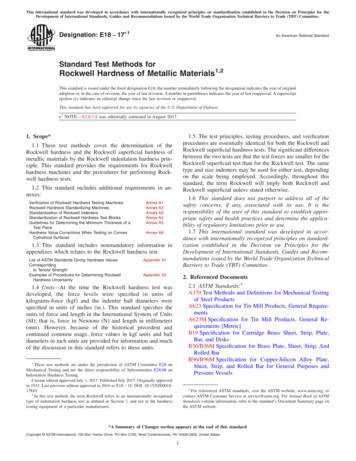
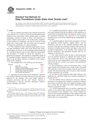
D3689 – 07corrosion or damage, or material properties compromised byfatigue, bending, or excessive heat, may rupture suddenlyunder load. Do not use brittle materials for tension connections.NOTE 2—Deep foundations sometimes include hidden defects that maygo unnoticed prior to static testing. Low strain integrity tests as describedin Test Method D5882 and ultrasonic crosshole integrity tests as describedin Test Method D6760 may provide a useful pre-test evaluation of the testfoundation.6. Apparatus for Applying and Measuring Loads6.1 General:6.1.1 The apparatus for applying tensile loads to a test pileor pile group shall conform to one of the methods described in6.3-6.6. The method in 6.3 is recommended. The method in 6.5can develop high tensile loads with relatively low jackingcapacity, but does not perform well for tests to failure or forlarge upward movements.6.1.2 Reaction piles, if used, shall be of sufficient numberand installed so as to safely provide adequate reaction capacitywithout excessive movement. When using two or more reaction piles at each end of the test beam(s), cap them withreaction beams (Fig. 1). Locate reaction piles so that resultanttest beam load supported by them acts at the center of thereaction pile group. Cribbing, if used as a reaction, shall be ofsufficient plan dimensions to transfer the reaction loads to thesoil without settling at a rate that would prevent maintainingthe applied loads.6.1.3 Cut off or build up reaction piles as necessary to placethe reaction or test beam(s). Remove any damaged or unsoundmaterial from the top of the reaction piles, and provide asmooth bearing surface parallel to the reaction or test beam(s).To minimize stress concentrations due to minor surface irregularities, set steel bearing plates on the top of precast orcast-in-place concrete reaction piles in a thin layer of quick-FIG. 1 Typical End Views of Test Beam(s) and Reaction Pile(s)Copyright by ASTM Int'l (all rights reserved); Mon Jul 5 12:16:21 EDT 20103Downloaded/printed byAli Qzaz () pursuant to License Agreement. No further reproductions authorized.setting, non-shrink grout, less than 6 mm (0.25 in.) thick andhaving a compressive strength greater than the reaction pile atthe time of the test. For steel reaction piles, weld a bearingplate to each pile, or weld the cap or test beam(s) directly toeach pile. For timber reaction piles, set the bearing plate(s)directly on the cleanly cut top of the pile, or in grout asdescribed for concrete piles.6.1.4 Provide a clear distance between the test pile(s) andthe reaction piles or cribbing of at least five times themaximum diameter of the largest test or reaction pile(s), butnot less than 2.5 m (8 ft). The engineer may increase ordecrease this minimum clear distance based on factors such asthe type and depth of reaction, soil conditions, and magnitudeof loads so that reaction forces do not significantl
ASME B30.1 Jacks3 ASME B40.100 Pressure Gages and Gauge Attachments3 ASME B89.1.10.M Dial Indicators (For Linear Measure-ments)3 3. Terminology 3.1 Definitions—For common definitions of terms used in this standard see Terminology D653. 3.2 Definitions of Terms Specific to This Standard: 3.2.1 cast in-place pile, n—a deep foundation unit made of cement grout or concrete and constructed .