Transcription
Syrian Private UniversityFaculty of Computer & InformaticsEngineeringDesign and the mechanism ofcontrolling a robotic armA Senior Project Presented to the Faculty of Computer andInformatics Engineering In Partial Fulfillment of the Requirementsfor the DegreeOf Bachelor of in Communication & Network EngineeringUnder the supervision ofProf. Ahmad Rateb Al-NajjarIProf. Ali Skaff
ByNoor Ali Al teefYousef Sofyan JghefHasan Mohamed HeddehMohamed Zaki Hani IbrahimMohammed Ali Ismail Abdul RahmanAugust 2015 2015 - ALL RIGHTS RESERVEDCERTIFICATION OF APPROVALII
Prof. Ahmad Rateb Al-NajjarDate -Prof. Ali SkaffDate III
CONTENTTable of Figure . VICHAPTER 1: INTRODUCTION . 2CHAPTER 2: DESIGNING PORTION . 32.1 Design Of Robotic Arm . 32.2 Five degrees of freedom . 42.3 Positive and negative on robotic arm . 52.3.1 The Positive : . 52.3.2 The negative : . 6CHAPTER 3: THEORETICAL PORTION . 73.1 Arduino. 73.2 Specifications . 83.3 Programming . 93.4 Power. 93.5 Memory . 103.6 Arduino development "IDE" . 11CHAPTER 4: PRACTICAL PORTION . 134.1 Servo Motors . 134.2 Theory of DC Servo Motor . 154.3 Separately Excited DC Servo Motor . 154.3.1 DC Servo Motor Theory : . 15Field Controlled DC Servo Motor Theory . 164.3.2 Armature Controlled DC Servo Motor Theory: . 184.3.3 Permanent Magnet DC Servo Motor : . 194.4 Deriving State Equations for a DC Servo Motor . 19IV
4.4.1System Model : . 194.4.2 Developing The State Equations : . 204.5 Potentiometers . 224.6 Bluetooth HC-06 module . 234.7 Specifications . 244.7.1 Hardware features . 244.7.2 Software features . 24CHAPTER 5: MECHANICAL PORTION . 285.1Mechanical Design . 295.2 Driving engines using complementary angle . 345.3 Robot Arm Control. 345.4 End-Effector Selection . 355.5 MIT App Inventor . 365.6 Robotic arm app using MIT app inventor . 375.6.1 Interface designer : . 395.6.2 Interface Blocks: . 405.6.3 App Designer: . 405.6.4 Arm Block Diagram: . 41CONCLUSION . 43REFERENCE . 44Appendix A . 46V
Table of FigureFigure2.1 shows the image of a servo motor4Figure2.2 Five degrees of freedom4Figure2.3 Robot Arm5Figure3.1 Arduino Uno microcontroller board (interface)7Figure 3.2 Arduino Uno microcontroller board(back view)8Figure 3.3 Arduino Power Supply10Figure 3.4 ATmega328P – Memory10Figure 3.5 Interface Arduino Uno Program11Figure 4.1 Big Servo Motor13Figure 4.2 G9 Servo Motor14Figure 4.3 Block diagram of a Servo motor14Figure 4.4 Separately Excited DC Servo Motor15Figure 4.5 Field controlled DC servo motor16Figure 4.6 knee point of magnetizing saturation curve17Figure 4.7 knee point of magnetizing saturation18Figure 4.8 The terms Ra and La are the resistance20Figure 4.9 Simulation Diagram For The DC Servo Motor21Figure 4.10 A Potentiometer22Figure 4.11 Circuit Diagram of a Potentiometer23Figure 4.12 Bluetooth HC.06 module (Front View)24Figure 4.13 Bluetooth HC.06 module(Back View)24VI
Figure 5.1 Free body diagram of the robot arm26Figure 5.2 Work region of the robotic arm27Figure 5.3 Force diagram of robot arm27Figure 5.4 Force diagram of link CB28Figure 5.5 Two Type Of Servo Motor30Figure 5.6 Electronic scheme of control32Figure 5.7 gripper Closed , gripper Open33Figure 5.8 MIB Structure34Figure5.9 Interface designer36Figure5.10 Interface Blocks37Figure 5.11 App Designer38Figure 5.12 Arm Block Diagram39VII
الملخص باللغة العربية تمحووت الدرا د ووحلدرح روووحلحووتولتموومورلت ميووحلم رووم دصلد روووح ضووم ل خموودلا يو المو لدرح وووحلتتوورلتمتوووال ل و رمهات لرتسيووملدرمٍو رلدر وووهحل لو ولا وو رلت م و ول او ل ومتاال مح و ال وو فتلتدرتوولتووترل اماووحل مركلفون لدرمو االدرخفوفوحلدره واوحلدرتوولت وتلدروم دصلد رووحلم ا در و هل ووو لد ، م صإلل ةض و فحلدر و لتااوووحلح و الدرووم دصرلد لدرمووتح رلدرووم لووووتالدرمح و التاووكلراو و ل دروا ال ا لتااوولدرتضاوحر ل تو ووترل ماوو ووحلدرت يمو ووحل ا و و لدرمو ووتح رلم و و لسو ووتص سمهل ATMEGA-328p ل و ووتخادرل ميو ووحل Arduino رلوووترلد ووتخادرلمو و وودلدريٍووالعوض و ةلرا ل و ل و لمدتوووحلدرووات دالتدةل و دالدرم وواحلدر و ل درمتح ررل ةم لدرتح رل رم دصلد روحلعوض ةل تخادرليٍ ملعسا توارلففول ررلدروترإللت وو لع للوم ل درم دصلد روحلي ر حلراسفعلدرا ررل ةض فحلدر لدر ت تتو التد ، تمتوحإللفون للوم لد ، سوتدصلمو لد ، م صلتمتو مل تستصلته وو تٍ لدرمت ححلفول االمي الالعخ ىر ل ل ل ل ل ل ل 1
CHAPTER 1: INTRODUCTIONA Robot is a virtually intelligent agent capable of carrying out tasks robotically with thehelp of some supervision. Practically, a robot is basically an electro-mechanical machinethat is guided by means of computer and electronic programming.Robots can beclassified as autonomous, semiautonomous and remotely controlled. Robots are widelyused for variety of tasks such as service stations, cleaning drains, and in tasks that areconsidered too dangerous to be performed by humans. A robotic arm is a roboticmanipulator, usually programmable, with similar functions to a human arm.This Robotic arm is programmable in nature and it can be manipulated. The robotic armis also sometimes referred to as anthropomorphic as it is very similar to that of a humanhand. Humans today do all the tasks involved in the manufacturing industry bythemselves. However, a Robotic arm can be used for various tasks such as welding,drilling, spraying and many more. A self-sufficient robotic arm is fabricated by usingcomponents like micro-controllers and motors. This increases their speed of operationand reduces the complexity. It also brings about an increase in productivity which makesit easy to shift to hazardous materials. The main part of the design is ATMEGA-328pmicro-controller which coordinates and controls the product’s action. This specific microcontroller is used in various types of embedded applications. Robotics involves elementsof mechanical and electrical engineering, as well as control theory, computing and nowartificial intelligence. According to the Robot Institute of America, ―A robot is areprogrammable, multifunctional manipulator designed to move materials, parts, tools orspecialized devices through variable programmed motions for the performance of avariety of tasks.The robots interact with their environment, which is an important objective in thedevelopment of robots. This interaction is commonly established by means of some sortof arm and gripping device or end effectors. In the robotic arm, the arm has a few joints,similar to a human arm, in addition to shoulder, elbow, and wrist, coupled with the finger2
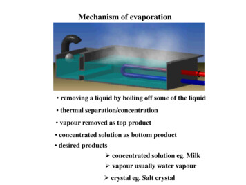
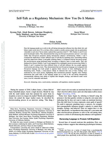
joints; there are many joints . The design process is clearly explained in the next sectionwith detailed information regarding the components which are used.CHAPTER 2: DESIGNING PORTION2.1 Design of Robotic ArmThe Robotic Arm is designed using the Microcontroller i.e. ATMEGA328pMicro-controller using Arduino programming. This process works on the principle ofinterfacing servos and potentiometers. This task is achieved by using Arduino board.Potentiometers play an important role The remote is fitted with potentiometers and theservos are attached to the body of the robotic arm. The potentiometer converts themechanical motion into electrical motion. Hence, on the motion of the remote thepotentiometers produce the electrical pulses, which are in route for the Arduino board.The board then processes the signals received from the potentiometers and finally,converts them into requisite digital pulses that are then sent to the servomotors. Thisservo will respond with regards to the pulses which results in the moment of the arm.Figure 2.1 shows the image of a servo motor. It consists of a motor which iscoupled to a sensor, used for position feedback, through a reduction gearbox. It alsoaccompanies a relatively sophisticated controller, usually a dedicated module designedspecifically for use with servo motorsIn short, the micro controller interfaces all these components specified below. Ashort list of components include1. Servo motors2. Potentiometers3. Atmega 328p.4. Arduino Deumilanove "IDE"5. Bloutooth module.3
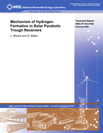
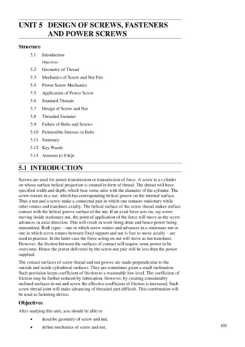
Figure2.1 shows the image of a servo motor2.2 Five degrees of freedomSerial and parallel manipulator systems are generally designed to position an endeffector with five degrees of freedom, consisting of three in translation and tow inorientation. This provides a direct relationship between actuator positions and theconfiguration of the manipulatorFigure2.2 Five degrees of freedom4
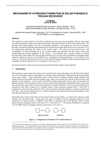
Robot arms are described by their degrees of freedom. This number typicallyrefers to the number of single-axis rotational joints in the arm, where higher numberindicates an increased flexibility in positioning a tool. This is a practical metric, incontrast to the abstract definition of degrees of freedom which measures the aggregatepositioning capability of a system.Figure2.3 Robot Arm2.3 Positive and negative on robotic arm2.3.1 The Positive: Increase productivity Use equipment effectively Reduce working costs Flexibility at work Get the job done in the shortest time Provide good returns on investment Better accuracy in performance Ability to work in risky ways and make it more safe5
2.3.2 The negative: Cause unemployment for manual workers High initial cost designed Arm to perform specific tasks and not comparable tothe human hand Difficulty programmed to perform Accurate tasks Needed a large number of sensors and high accuracy to perform theComplex tasks And other technical problems, "especially in the fields of artificialintelligence and Machine vision" . When the Robotic arm break down the production line will go off in thefactories.6
CHAPTER 3: THEORETICAL PORTION3.1 ArduinoArduino Uno is a microcontroller board based on the ATmega328P . It has 14digital input/output pins (of which 6 can be used as PWM outputs), 6 analog inputs, a 16MHz quartz crystal, a USB connection, a power jack and a reset button. It containseverything needed to support the microcontroller; simply connect it to a computer with aUSB cable or power it with a AC-to-DC adapter or battery to get started. You can tinkerwith your UNO without worrying too much about doing something wrong, worst casescenario you can replace the chip for a few dollars and start over again.Figure3.1 Arduino Uno microcontroller board (interface)"Uno" means one in Italian and was chosen to mark the release of ArduinoSoftware (IDE) 1.0. The Uno board and version 1.0 of Arduino Software (IDE) were thereference versions of Arduino, now evolved to newer releases. The Uno board is the firstin a series of USB Arduino boards, and the reference model for the Arduino platform; foran extensive list of current, past or outdated boards see the Arduino index of boards.7
Figure 3.2 Arduino Uno microcontroller board (back view)3.2 SpecificationsMicrocontrollerATmega328POperating Voltage5VInput Voltage (recommended)7-12VInput Voltage (limit)6-20VDigital I/O Pins14 (of which 6 provide PWM output)PWM Digital I/O Pins6Analog Input Pins6DC Current per I/O Pin20 mADC Current for 3.3V Pin50 mAFlash Memory32KB8(ATmega328P)
of which 0.5 KB used by bootloade*rSRAM2 KB (ATmega328P)EEPROM1 KB (ATmega328P)Clock Speed16 MHzLength68.6 mmWidth53.4 mmWeight25 g3.3 ProgrammingThe Arduino Uno can be programmed with the (Arduino Software (IDE)).TheATmega328 on the Arduino Uno comes preprogrammed with a bootloader that allowsyou to upload new code to it without the use of an external hardware programmer. Itcommunicates using the original STK500 protocol.3.4 PowerThe Arduino Uno board can be powered via the USB connection or with anexternal power supply. The power source is selected automatically.External (non-USB) power can come either from an AC-to-DC adapter (wallwart) or battery. The adapter can be connected by plugging a 2.1mm center-positive pluginto the board's power jack. Leads from a battery can be inserted in the GND and Vin pinheaders of the POWER connector.9
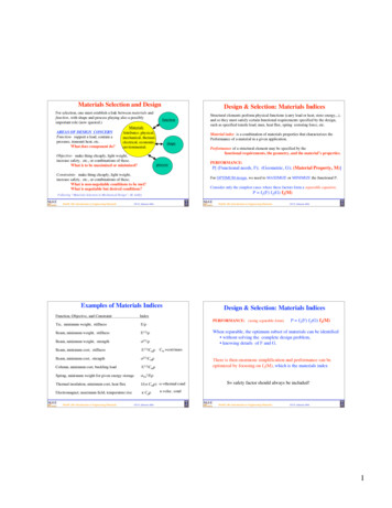
Figure 3.3 Arduino Power Supply3.5 MemoryThe ATmega328 has 32 KB (with 0.5 KB occupied by the bootloader). It also has2 KB of SRAM and 1 KB of EEPROM3%6%2%SRAM - 2 KillobyteFlash Disk - 29 KillobyteEEPROM - 1 KillobyteBootloader 0.5 Killobyte89%Figure 3.4 ATmega328P – Memory10
3.6 Arduino development "IDE"The Arduino integrated development environment (IDE) is a cross-platformapplication written in Java, and is derived from the IDE for the Processing programminglanguage and the Wiring projects. It is designed to introduce programming to artists andother newcomers unfamiliar with software development. It includes a code editor withfeatures such as syntax highlighting, brace matching, and automatic indentation, and isalso capable of compiling and uploading programs to the board with a single click. Thereis typically no need to edit make files or run programs on a command-line interfaceFigure 3.5 Interface Arduino Uno Program11
Developer(s)Arduino SoftwareStable release1.0.3 / December 10, 2012; 3monthsagoWritten inJava, C and C Operating systemCross-platformTypeIntegrated development environmentWebsitearduino.ccArduino programs are written in C or C The Arduino IDE comes with a softwarelibrary called "Wiring" from the original Wiring project, which makes many commoninput/output.Operations much easier. Users only need define two functions.To make a runnable cyclic executive program: Setup (): a function run once at the start of a program that can initialize settings. Loop (): a function called repeatedly until the board powers off.12
CHAPTER 4: PRACTICAL PORTION4.1 Servo MotorsServo refers to an error sensing feedback control which is used to correct theperformance of a system. Servo or RC Servo Motors are DC motors equipped with aservo mechanism for precise control of angular position.The RC servo motors usually have a rotation limit from 90 to 180 . But servos do notrotate continually. Their rotation is restricted in between the fixed angles.The Servos are used for precision positioning. They are used in robotic arms and legs,sensor scanners and in RC toys like RC helicopter, airplanes and cars.The specifications for big Servomotor used are as follows: Weight- 55g Dimension- 40.7*19.7*42.9mm Stall torque- 10kg/cm Operating speed-0.20sec/60degree(4.8v) Operating voltage 4.8-7.2V. Temperature range 0-55 degrees.Figure 4.1 Big Servo Motor13
The specifications for small Servomotor G9 used are as follows: Weight: 9 g Dimension: 22.2 x 11.8 x 31 mm approx. Stall torque: 1.8 kgf·cm Operating speed: 0.1 s/60 degree Operating voltage: 4.8 V ( 5V) Dead band width: 10 µs Temperature range: 0 ºC – 55 ºCFigure 4.2 G9 Servo MotorFigure 4.3 Block diagram of a Servo motor14
4.2 Theory of DC Servo MotorAs we know that any electrical motor can be utilized as servo motor if it iscontrolled by servomechanism. Likewise, if we control a DC motor by means ofservomechanism, it would be referred as DC servo motor. There are different types ofDC motor, such shunt wound DC motor, series DC motor, Separately excited DC motor,permanent magnet DC motor, Brushless DC motor etc. Among all mainly separatelyexcited DC motor, permanent magnet DC motor and brush less DC motor are used asservo.4.3 Separately Excited DC Servo MotorFigure (4.4) shows the block diagram of the separately excited Dc servo motorFigure 4.4 Separately Excited DC Servo Motor4.3.1 DC Servo Motor Theory:The motors which are utilized as DC servo motors, generally have separate DCsource for field winding and armature winding. The control can be archived either bycontrolling the field current or armature current. Field control has some specificadvantages over armature control and on the other hand armature control has also somespecific advantages over field control. Which type of control should be applied to the DC15
servo motor, is being decided depending upon its specific applications. Let's discus DCservo motor working principle for field control and armature control one by one.Field Controlled DC Servo Motor TheoryThe Figure below illustrates the schematic diagram for a field controlled DCservo motor. In this arrangement the field of DC motor is excited be the amplified errorsignal and armature winding is energized by a constant current sourceFigure 4.5 Field controlled DC servo motorThe field is controlled below the knee point of magnetizing saturation curve. Atthat portion of the curve the MMF linearly varies with excitation current. That meanstorque developed in the DC motor is directly proportional to the field current below theknee point of magnetizing saturation curve.16
Figure 4.6 knee point of magnetizing saturation curveFrom general torque equation of DC motor it is found that, torque T φIa.Where, φ is field flux and Ia is armature current. But in field controlled DC servo motor,the armature is excited by constant current source , hence Ia is constant here. Hence, T φAs field of this DC servo motor is excited by amplified error signal, the torque ofthe motor i.e. rotation of the motor can be controlled by amplified error signal. If theconstant armature current is large enough then, every little change in field current causescorresponding change in torque on the motor shaft.The direction of rotation can be changed by changing polarity of the field.The direction of rotation can also be altered by using split field DC motor, wherethe field winding is divided into two parts, one half of the winding is wound in clockwisedirection and other half in wound in anticlockwise direction. The amplified error signal isfed to the junction point of these two halves of the field as shown below. The magneticfield of both halves of the field winding opposes each other. During operation of themotor, magnetic field strength of one half dominates other depending upon the value ofamplified error signal fed between these halves. Due to this, the DC servo motor rotatesin a particular direction according to the amplified error signal voltage.17
The main disadvantage of field control DC servo motors, is that the dynamicresponse to the error is slower because of longer time constant of inductive field circuit.The field is an electromagnet so it is basically a highly inductive circuit hence due tosudden change in error signal voltage, the current through the field will reach to its steadystate value after certain period depending upon the time constant of the field circuit. Thatis why field control DC servo motor arrangement is mainly used in small servo motorapplications.The main advantage of using field control scheme is that, as the motor is controlled byfield. The controlling power requirement is much lower than rated power of the motor.4.3.2 Armature Controlled DC Servo Motor Theory:Figure (4.5) shows the schematic diagram for an armature controlled DC servomotor. Here the armature is energized by amplified error signal and field is excited by aconstant current source .The field is operated at well beyond the knee point of magnetizing saturationcurve. In this portion of the curve, for huge change in magnetizing current, there is verysmall change in mmf in the motor field. This makes the servo motor is less sensitive tochange in field current. Actually for armature controlled DC servo motor, we do not wantthat, the motor should response to any change of field current.18
Figure 4.7 knee point of magnetizing saturationAgain, at saturation the field flux is maximum. As we said earlier, the generaltorque equation of DC motor is, torque T φIa. Now if φ is large enough, for every littlechange in armature current Ia there will be a prominent changer in motor torque. Thatmeans servo motor becomes much sensitive to the armature current.As the armature of DC motor is less inductive and more resistive, time constant ofarmature winding is small enough. This causes quick change of armature current due tosudden change in armature voltage.That is why dynamic response of armature controlled DC servo motor is muchfaster than that of field controlled DC servo motor.The direction of rotation of the motor can easily be changed by reversing the polarity ofthe error signal.4.3.3 Permanent Magnet DC Servo Motor:Field control is not possible in the case of permanent magnet DC motor as thefield is a permanent magnet here. DC servo motor working principle in that case issimilar to that of armature controlled motor.4.4 Deriving State Equations for a DC Servo Motor4.4.1System Model:A useful component in many real control systems is a permanent magnet DC servomotor. The input signal to the motor is the armature voltage Va(t), and the output signalis the angular position θ(t). A schematic diagram for the motor is shown in Figure.(4.4.1.1). The terms Ra and La are the resistance and inductance of the armature windingin the motor, respectively. The voltage Vb is the back EMF generated internally in themotor by the angular rotation. J is the inertia of the motor and load (assumed lumpedtogether), and B is the damping in the motor and load relative to the fixed chassis.19
Figure 4.8 The terms Ra and La are the resistanceThe equations for the electrical side of the system areVa(t) Raia(t) La dia(t)/dt Vb(t) withVb(t) Kb dθ(t) /dtVa(t) Raia(t) La dia(t)/ dt Kb dθ(t) /dt(2)(1)Where Kb is the motor’s back EMF constant. The equations for the mechanical side ofthe system areJ d2θ(t)/ dt2 B dθ(t)/ dt Tapp(t)withJ d2θ(t)/ dt2 B dθ(t)/ dt KT ia(t)Tapp(t) KT ia(t)(3)(4)Where Tapp is the applied torque, and KT is the torque constant that relates the torque tothe armature current.4.4.2 Developing the State Equations:Here are three derivative terms in the system model for the DC servo motor—firstderivative of ia(t) in Eqn. (2) and first and second derivatives of θ(t) in Eqn. (4).Therefore, there are a total of 3 state variables in the state space model. Although the firstderivative of θ(t) appears in both of those equations, it is the same variable and so doesnot add an additional state variable. A simulation diagram can be drawn for this systemby solving Eqns. (2) and (4) for the highest derivative term in each. This yields the20
expressions in (5) and (6). The simulation diagram is shown in Figure. 2. The statevariables will be defined as the outputs of the integrators, with x1 being ia, x2 being θ,and x3 being dθ/dt.dia(t) /dt (Ra/ La )¶ ia(t) – (Kb /La ¶) dθ(t) /dt ( 1 /La )¶ Va(t)(5)d 2θ(t)/ dt 2 (B/ J) ¶ dθ(t)/ dt (KT/ J) ¶ ia(t)(6)Figure 4.9 Simulation Diagram for The DC Servo MotorExample With these definitions for the state variables, and definingu(t) Va(t) and y(t) θ(t), the state and output equations are:x1(t) (Ra/ La )¶ x1(t) – (Kb/ La )¶ x3(t) ( 1/ La )¶ u(t)x2(t) x3(t)(7)(8)x3(t) (B /J )¶ x3(t) (KT /J) ¶ x1(t)(9)21
y(t) x2(t)(10)In short hand notation, the state and output equations are :x(t) Ax (t) Bu (t),y (t) Cx (t)(11)4.5 PotentiometersA Potentiometer is a variable resistor. The two output terminals act as a fixedresistor. A movable contact called a wiper (or a slider) moves across the resistor,producing a variable resistance between the center terminals and the two sides. Apotentiometer is basically a voltage divider which is used for the measurement ofpotential. Potentiometers are commonly used to control electrical devices such as volumecontrols on audio equipment. Potentiometers which are operated by a mechanism canalso be used as position transducer.Figure 4.10 A Potentiometer22
A potentiometer is a manually adjustable electrical resistor that uses threeterminals. In many electrical devices, potentiometers are establishes the levels of output.For example, in case of a loudspeaker, a potentiometer is used to adjust the volume ortaken the case of a television set, computer monitor or light dimmer; it can be used tocontrol the brightness of the screen or light bulb.Figure 4.11 Circuit Diagram of a Potentiometer4.6 Bluetooth HC-06 moduleHC.06 module is an easy to use Bluetooth SPP (Serial Port Protocol) module,designed for transparent wireless serial connection setup. Serial port Bluetooth module isfully qualified Bluetooth V2.0 EDR (Enhanced Data Rate) 3Mbps Modulation withcomplete 2.4GHz radio transceiver and baseband. It uses CSR Blue core 04.Externalsinglechip Bluetooth system with CMOS technology and with AFH(AdaptiveFrequency Hopping Feature). It has the footprint as small as 12.7mmx27mm.23
Figure 4.12 Bluetooth HC.06 module (Front View)Figure 4.13 Bluetooth HC.06 module(Back View)4.7 Specifications4.7.1 Hardware features Typical .80dBm sensitivity Up to 4dBm RF transmit power Low Power 1.8V Operation ,1.8 to 3.6V I/O PIO control UART interface with programmable baud rate With integrated antenna With edge connector4.7.2 Software features Default Baud rate: 38400, Data bits: 8, Stop bit: 1, Parity: No parity, Data24
Control: has supported baud rate:9600,19200,38400,57600,115200,230400,460800. Given a rising pulse in PIO0, device will be disconnected. Status instruction port PIO1: low disconnected, high connected; PIO10 and PIO11 can be connected to red and blue led separately. When masterand slave are paired, red and blue led blinks 1time/2s in interval, whiledisconnected only blue led blinks 2times/s. Auto connect to the last device on power as default. Permit pairing device to connect as default. Auto pairing PINCODE:‖0000‖ as default Auto reconnect in 30 min when disconnected as a result of beyond the range ofconnection.25
CHAPTER 5: MECHANICAL PORTION5.1Mechanical DesignThe mechanical design of the robot arm is based on a robot manipulator withsimilar functions to a human arm . The links of such a manipulator are connected byjoints allowing rotational motion and the links of the manipulator is considered to form akinematic chain. The business end of the kinematic chain of the manipulator is called theend
Figure 4.1 Big Servo Motor 13 Figure 4.2 G9 Servo Motor 14 . Figure 5.1 Free body diagram of the