Transcription
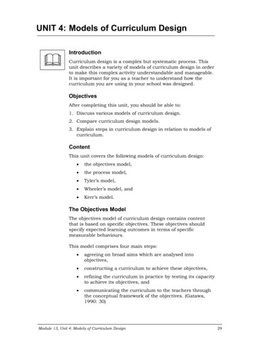
UNIT 5 DESIGN OF SCREWS, FASTENERSAND POWER SCREWSDesign of Screws,Fasteners and ometry of Thread5.3Mechanics of Screw and Nut Pair5.4Power Screw Mechanics5.5Application of Power Screw5.6Standard Threads5.7Design of Screw and Nut5.8Threaded Fastener5.9Failure of Bolts and Screws5.10 Permissible Stresses in Bolts5.11 Summary5.12 Key Words5.13 Answers to SAQs5.1 INTRODUCTIONScrews are used for power transmission or transmission of force. A screw is a cylinderon whose surface helical projection is created in form of thread. The thread will havespecified width and depth, which bear some ratio with the diameter of the cylinder. Thescrew rotates in a nut, which has corresponding helical groove on the internal surface.Thus a nut and a screw make a connected pair in which one remains stationary whileother rotates and translates axially. The helical surface of the screw thread makes surfacecontact with the helical groove surface of the nut. If an axial force acts on, say screwmoving inside stationary nut, the point of application of the force will move as the screwadvances in axial direction. This will result in work being done and hence power beingtransmitted. Both types – one in which screw rotates and advances in a stationary nut orone in which screw rotates between fixed support and nut is free to move axially – areused in practice. In the latter case the force acting on nut will move as nut translates.However, the friction between the surfaces of contact will require some power to beovercome. Hence the power delivered by the screw-nut pair will be less than the powersupplied.The contact surfaces of screw thread and nut groove are made perpendicular to theoutside and inside cylindrical surfaces. They are sometimes given a small inclination.Such provision keeps coefficient of friction to a reasonable low level. The coefficient offriction may be further reduced by lubrication. However, by creating considerablyinclined surfaces in nut and screw the effective coefficient of friction is increased. Suchscrew thread joint will make advancing of threaded part difficult. This combination willbe used as fastening device.ObjectivesAfter studying this unit, you should be able to describe geometry of screw and nut, define mechanics of screw and nut,105
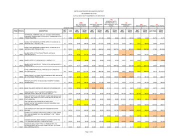
Machine Design determine forces on screw and nut threads, calculate dimensions of screw and nut for transmission of force, and find the force on screw fastener and load transmitted to parts jointed byfasteners.5.2 GEOMETRY OF THREADLook at Figures 5.1(a) and (b) and you will get a fair idea how would a screw and a nutappear. The screw will pass into nut by rotating either of them. For understanding how ahelical thread can be formed on a cylinder you can take a plane sheet of paper and drawan inclined line on it. Then roll the paper to form a cylinder by bringing two oppositeedges of the paper together. The line which you drew will appear like a helix on thesurface of the cylinder. A line drawn as AC, inclined at angle with horizontal line AA1,will be wrapped on the cylinder to AA , looking like a helix. AA1, becomes thecircumference of the cylinder and A coincides with C. In Figure 5.2, you can see twoparallel lines AC and A C drawn inclined at to horizontal and then paper wrapped toform a cylinder and thus two threads are formed on cylinder. p is the vertical distancebetween A and C or between C and C . If the paper is wrapped such that the lines drawnare on the inside surface, you can get the idea of internal thread.dP/2d1DopDp/2(a) A Screw(b) A NutFigure 5.1 : Screw and Nut with Helical Surfaces Cut on Outside and InsideSurfaces of Cylinders, respectivelyC’C’C”A’CPA”dAdA1Figure 5.2 : Formation of a Helix on the Cylindrical Surface106The distance A1C which is equal to AA and A C is called the pitch of the screw. Pitch isapparently the distance between two corresponding points on two consecutive threads.The angle between the base of the triangle and hypotenuse becomes the angle of helix.Obviously,
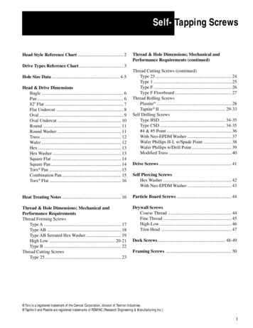
p d tan ortan Design of Screws,Fasteners and PowerScrewsp d. . . (5.1)If the helix on the outside surface ascends from right to left the thread is left hand. Sucha threaded screw will have to be turned counter clockwise to engage the mating nut. Onthe other hand a right hand screw will be turned clockwise and its helix will appear toascend from left to right. The thread shown in Figure 5.2 is left hand. If a plane figure,say a triangle or trapeziums placed in contact with the outer surface of the base cylinderon which the helical line was created and then is made to rotate round the cylinder alongthe helix then the helical surfaces will be formed on the base cylinder giving rise tothread as can be seen in Figure 5.3. If the generating plane section is a square, a squarethread is created. The thread depicted in Figure 5.1(a) is a square thread. The Vee threadis created by a triangular section while trapezoidal thread has a trapezium section. Thisthread is also known as the Acme thread. Buttress thread has a triangular section but oneside of the triangle is perpendicular to the axis. The square, the Acme and the buttressthreads are used for power transmission, as they are more efficient than the Vee thread.The square thread is most efficient but difficult to produce and hence becomes costly.The adjustment for wear in square thread is very difficult but can be easily achieved inthe Acme threads, by splitting the nut along the axis. The Acme threads thus can be usedas power transmission element when power is to be transmitted in both the directions.Bose cylinderHelix createdin Figure 5.2ThreadGeneratingrectangleFigure 5.3 : Generating a Square Section Thread on Cylindrical SurfaceThere is little or no backlash in the Acme threads which are commonly used as feed andlead screws of machine tools. The buttress thread having one side flat and other slopingcombines the advantage of square thread and Acme thread. The flat side provides theefficiency of power transmission while the inclined side provides the ease of adjustment.However, these advantages become possible only when the power is transmitted in onedirection. Vee threads for their lower efficiency for power transmission are used asfasteners. Due to sides being inclined the effective coefficient of friction between thescrew and the nut increases. Figure 5.4 shows Vee or triangular, the Acme and thebuttress threads with leading nomenclature.The major diameter is the largest diameter of the screw thread denoted by d for externalthread and by D for internal thread. Minor diameter (d1 or D1) is the smallest diameter ofthe screw. Some times more than one thread may be cut on the screw. These multiplethreads may be easily seen at the end of the screw where more than one thread willappear to start. Multiple start threads give the advantage that screw can move through alonger distance in the nut when given one rotation as compared to the screw with asingle thread or start. The distance moved by a screw along its axis when given onerotation is called the lead. Apparentlylead number of starts pitch. . . (5.2)107
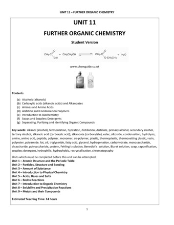
ThreadangleMachine DesignCrestRoot45oddmd145oPVee Thread(a) Vee ThreadP0.370.5p 0.25mmd1dmd(b) Acme ThreadP/245 o0.245PP0.503Pddmd10.89P0.139P(C) Buttress thread(c) Buttress ThreadFigure 5.4The V-threads are standardized by several organizations wherein nominal majordiameter, pitch and pitch diameters are described. According to IS : 1362-1962 a screwthread (VEE type) is designated by letter M followed by nominal major diameter. AnM 1.6 thread has nominal major diameter of 1.6 mm. IS : 4694-1968 describes basicdimensions of square threads.5.3 MECHANICS OF SCREW AND NUT PAIRIt was mentioned earlier that the motion between nut and screw is like a body moving onan inclined plane. Figures 5.5(a) and (b) will explain this motion. The body of weight Wis pushed up the inclined plane by a force P which acts upon the body horizontally. Thisinclined plane is bent round a cylinder in Figure 5.5(b) and aome body is being pushedup the plane while force P remains horizontal but also tangential to circular path of thebody. This illustrates how the motion of the nut on the thread is similar to motion of abody on an inclined plane. The weight of the body on the inclined plane is replaced byweight carried by the nut in axial direction. The force P is applied by the help of awrench and W may be the reaction developed between surfaces of contact.108
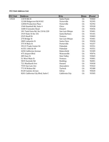
Design of Screws,Fasteners and PowerScrewsNPFW(a) Inclined PlaneBasecylinderrThreadW(b) Inclined Plane Wrapped Round a Base Cylinder to Form a ThreadFigure 5.5This is illustrated in Figures 5.6(a) and (b). Imagine that a lever is pivoted on the axis ofthe cylinder and pushes the body of weight W up the incline of helically wrapped planeon the cylinder. The lever touches the body at a radius r while a force P1 is applied onthe lever at an arm length of L. In the nomenclature we have already defined the outerdiameter of the thread as major diameter, d and the smallest diameter as the diameter ofdmthe cylinder, d1, (also called core diameter). r iswhere dm is the mean diameter of2thread, being mean of d and d1. If P be the force applied by the lever on the body ofweight W, then by taking moments of forces, acting upon the lever, about the axis of thecylinder.P 2 P1 Ldm. . . (5.3)ThreadsCoads addupto WNutWrenMchP1(a)dm/2LNPFW P1(b)Figure 5.6109
Machine DesignThe force P has to overcome the friction as well as cause lifting of the body in verticaldirection. To find the relationship between force P, called effort, and weight of the body,W, we have to consider the equilibrium of the body on an inclined plane as shown inFigures 5.7(a) and (b). The free body diagram clearly shows forces along andperpendicular to the inclined plane.NPCos PWSin N WWCos PSin (a) A Body being Pushed Up the Inclined Plane with Angle of Inclination a, by a Horizontal Force PN Wcos PSin PCos WSin (b) Free Body Diagram of Body of Weight wFigure 5.7The sum of the forces perpendicular to the plane and sum of the forces along the planeshould separately be zero to satisfy the conditions of equilibrium. is taken ascoefficient of friction between the body and the plane, which is same as coefficient offriction between the nut and screw thread surfaces. tan where is the angle offriction.Summing up the forces perpendicular to the plane.The normal reaction,N W cos P sin Hence, force of friction between the surfaces of contactF N W cos P sin Summing up the forces parallel to the inclined planeP cos W sin W cos P sin ReplacingP cos by tan . . . (i)sin cos sin sin P sin W sin W cos cos cos p cos cos P sin sin W sin cos W cos sin . . . (ii)P cos ( ) W sin ( )P W tan ( ). . . (5.4)If there is no friction, 0 and effort in such a case is called ideal effort denoted by Piwhere110Pi W tan . . . (5.5)
Hence the efficiency of an inclined plane with inclination of or the efficiency of ascrew having helix angle isDesign of Screws,Fasteners and PowerScrewsPip tan tan ( ) . . . (5.6)If in a situation as shown in Figure 5.7(a), P is removed, will the body slide down?Obviously it will depend upon the fact as to how large angle is. If W sin W cos the body will slide down under its own weight (Examine (i) and (ii) with P 0). Samething will happen in case of a nut in Figure 5.6 (a), i.e. when effort P1 is removed fromthe wrench or wrench is removed, the nut will rotate back under load W. It means the nutis not self-locking. However, if is reduced it can be seen that at , the downwardcomponent (along the plane) of weight W, i.e. W sin and friction force (along theplane) W cos become equal and the body remains just stationary or the nut does notmove down. If , the body will need a force to act so as to push it down. If this forceis P thenP W tan ( ). . . (5.7)Naturally screws of , will not be self locking or in other words they cannot act asfasteners. If, however, the angle , an effort P , given by Eq. (5.7) will be required tounscrew the nut, and such screws can be used as fasteners.The Eq. (5.6) which defines the efficiency of the screw and that the condition for screwto be self locking is that can be used to determine the maximum efficiency of a selflocking screw and nut pair.For self locking condition, the efficiency s tan tan (1 tan 2 ) tan 2 2 tan tan tan ( )1 tan 2 2Since tan2 is always less than 1, ( tan ) s 12. . . (5.8)The screw having efficiency greater than 50% is said to over haul, meaning the load Wwill cause the nut to roll down.5.4 POWER SCREW MECHANICSIn the preceding section the simple case of a square thread was considered. As will beseen in the text that follows that the square thread is more efficient than the Acme threadbecause in the Acme thread the effective coefficient of friction increases, yet for powerscrews it is the Acme thread which is used more predominantly. The Acme thread can bemachined more easily than the square thread and more importantly the clearance in theAcme thread can be adjusted to take care of the wear or machining inaccuracy.Figure 5.8 shows the nuts in pair with square and the Acme threads and an adjustingmechanism for the acme thread.111
PartonnutMachine rew(c)Figure 5.8 : (a) A Square thread and Nut (b) An Acme Thread and Two Nuts for Adjusting Clearanceon Both sides of the Thread. Two Narrow nuts Threading on Outside of the nut Push the Two Nuts inOpposite Direction (c) Adjustment of Clearance on Two Sides of threadAn Acme thread has two inclination. Firstly the plane of the thread is sloping alongangle of helix in the direction of the helix. The plane of the thread also slopes away fromthe c
one in which screw rotates between fixed support and nut is free to move axially – are used in practice. In the latter case the force acting on nut will move as nut translates. However, the friction between the surfaces of contact will require some power to be overcome. Hence the power delivered by the screw-nut pair will be less than the power