Transcription
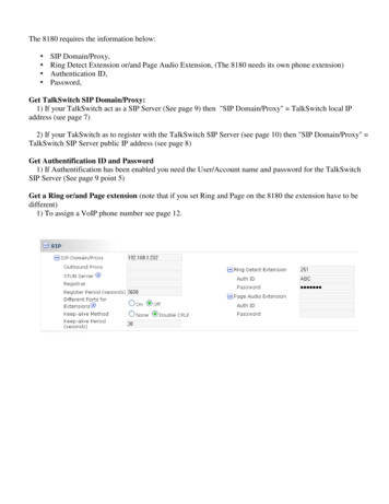
The 8180 requires the information below: SIP Domain/Proxy,Ring Detect Extension or/and Page Audio Extension, (The 8180 needs its own phone extension)Authentication ID,Password,Get TalkSwitch SIP Domain/Proxy:1) If your TalkSwitch act as a SIP Server (See page 9) then "SIP Domain/Proxy" TalkSwitch local IPaddress (see page 7)2) If your TakSwitch as to register with the TalkSwitch SIP Server (see page 10) then "SIP Domain/Proxy" TalkSwitch SIP Server public IP address (see page 8)Get Authentification ID and Password1) If Authentification has been enabled you need the User/Account name and password for the TalkSwitchSIP Server (See page 9 point 5)Get a Ring or/and Page extension (note that if you set Ring and Page on the 8180 the extension have to bedifferent)1) To assign a VoIP phone number see page 12.
TALKSWITCH DOCUMENTATIONVoIPNETWORKCONFIGURATION GUIDERELEASE4.0CT.TS005.00330 2.IAA NS W E RS WI TH I NTELLIGENCE
INTRODUCTIONAbout this guideThis guide is designed to help you plan and configure a TalkSwitch Voice over IP(VoIP) network.Note: For TalkSwitch provisioning with a VoIP service provider, please refer to thedocumentation located on our website. Visit http://global.talkswitch.com andselect country or region.Who should use this guideThis guide is intended for customers who have: Purchased a TalkSwitch system equipped with VoIP lines. Upgraded their existing TalkSwitch phone system with a compatible VoIP moduleand wish to configure it to use VoIP. Subscribed to a VoIP service and wish to use it as part of their TalkSwitchphone system.Where to go for further informationThe guides listed below, as well as other guides, can be found in the TalkSwitchfolder in the Windows Start menu, on the TalkSwitch software CD, and in thesupport section of our website. Visit http://global.talkswitch.com and selectcountry or region. For information on the initial installation and setup of a TalkSwitch phonesystem, refer to the TalkSwitch Start Guide. For additional information on VoIP functionality and advanced configuration,refer to the TalkSwitch User Guide.TroubleshootingThe TalkSwitch system and the configuration software are designed for ease ofuse. However, if you encounter difficulties with the installation or configurationof your TalkSwitch: Consult the documents in the TalkSwitch folder on your PC or on theTalkSwitch software CD. Access additional TalkSwitch information online, including FAQs and QuickGuides. Visit http://global.talkswitch.com and select country or region.Contacting Technical Support Contact your authorized TalkSwitch reseller. Visit http://global.talkswitch.com and select country or region. Provideyour company name and TalkSwitch product information.HTTP://GLOBAL.TALKSWITCH.COM1
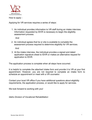
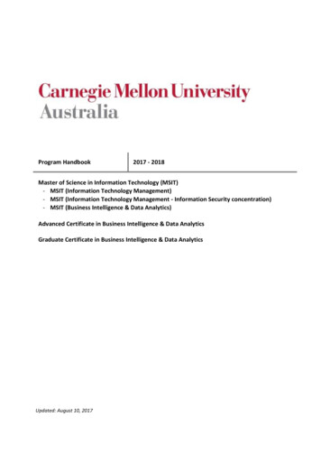
TALKSWITCH VoIPTalkSwitch uses the industry-standard Session Initiation Protocol (SIP) to makeand manage VoIP calls. In this guide the term SIP is often used in place of VoIP.To connect to a VoIP network or VoIP service to make and receive SIP calls, eachlocation must be able to establish a high-speed connection to the Internet, orprivate network. The steps below should ensure success for typical networkconnection methods.Connect to a LAN and IP networkEnsure the TalkSwitch or gateway is connected to a Local Area Network (LAN),equipped with an Ethernet switch and router, or a router with an integratedswitch. A PC should be connected to the LAN, for configuring the TalkSwitch, aswell as the router and/or switch.FIGURE 1. TalkSwitch network configurationConfirm the network connection has sufficient capacity for VoIPEnsure that the LAN in each location has a reliable high-speed broadbandconnection to the Internet. The quality of VoIP calls, especially on mixed voiceand data networks, depends on high data-transfer rates across the network. ‘Lite’broadband connections are not suitable for simultaneous voice and data traffic.To test the VoIP call capacity based on your Internet connection speed, perform thetest available on our website at:www.talkswitch.com/voip/voip test.asp.Ensure there is a path for voice data through your router/firewallIn order to pass through a router’s firewall, voice data received by your networkmust be mapped to the appropriate TalkSwitch unit. TalkSwitch uses UPnP(Universal Plug and Play) to automatically map firewall ports to forward VoIPdata. If your router supports UPnP, ensure that it is enabled (see your routerdocumentation for configuration details).2TALKSWITCH VOIP NETWORK CONFIGURATION GUIDE
If a router does not support UPnP, you will need to configure the router to mapspecific ports to TalkSwitch. The following describes which ports to map toTalkSwitch: To allow SIP Signaling data to be forwarded to TalkSwitch, firewall port 5060must be mapped to the TalkSwitch unit known as the Local Proxy. By default,this is the lowest numbered TalkSwitch on a LAN. The IP Configuration windowof the TalkSwitch software indicates with an asterix which TalkSwitch unit isthe Local Proxy (see example on page 7). SIP Signaling uses UDP.Example: in a 4-unit network, firewall port 5060 (UDP) would need to bemapped to the IP Address of the TalkSwitch unit ID #1. To allow voice traffic to be forwarded to TalkSwitch, corresponding ports mustbe mapped to each TalkSwitch unit. The following table shows the firewallports to map to each TalkSwitch unit on a LAN.Firewall ports† required open for VoIP communication with TalkSwitchDescription TypeUnit 1Voice Traffic UDP6000-6006 6010-6016 6020-6026 6030-6036†DefaultUnit 2Unit 3Unit 4port numbers. For instructions on re-assigning these numbers, contact TalkSwitch Technical Support. If you plan on configuring TalkSwitch remotely, you will need to map port 9393(Type: TCP) to the TalkSwitch unit that is being configured. Configuration isdone using TCP.TIP: For information on configuring a router for port forwarding, rt forwarding/routerindex.htm.Prioritize your voice trafficIf your Internet connection is shared between computers and TalkSwitch (i.e.data and voice), it is critical that the voice traffic has priority over the datatraffic. Many routers support Quality of Service (QoS) routing for this purpose. Ifyour router supports QoS, ensure that it is enabled (see your routerdocumentation for configuration details).DDNS SupportIf you are using Dynamic Domain Name Service (DDNS) to manage the IP addressof the SIP server, ensure that your router(s) support the specific DDNS servicethat you are using.If you are not setting up a VoIP network, but want to add VoIP service from aservice provider to your TalkSwitch system, proceed to Configure TalkSwitch tomake and manage VoIP calls on page 7.HTTP://GLOBAL.TALKSWITCH.COM3
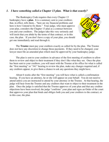
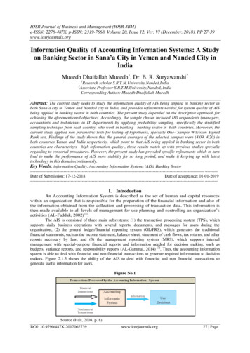
SETTING UP A VoIP NETWORKA TalkSwitch VoIP network can be set up in 4 steps:1.2.3.4.Connect a TalkSwitch or SIP-compatible gateway at each location.Select a TalkSwitch to use as the SIP network server.Assign phone numbers to each VoIP location.Configure TalkSwitch to make and manage VoIP calls.Connect TalkSwitch or SIP-compatible gatewaysIn order to create a VoIP network, a VoIP-equipped TalkSwitch or a VoIPcompatible gateway, such as a Mediatrix 2102, is required at each locationinstructions on page 2 describe how to do this.1. TheEach location in a multi-location network can support up to 4 TalkSwitch units,with a maximum of 32 local extensions (analog and/or IP phones) and 16 VoIPlines 2 per location.Example: The following is a multi-location network where two locations areequipped with TalkSwitch systems and a teleworker is equipped with aMediatrix 2102 device. TalkSwitch and the Mediatrix 2102 route VoIP callsover the Internet, while local calls are routed over the traditional telephonenetwork.FIGURE 2. Multi-location network with VoIP calling1The Mediatrix 2102 is a TalkSwitch-certified third-party SIP gateway that is ideal for smallbranch offices or teleworkers.2Up to 48 VoIP numbers can be assigned to the 16 VoIP lines.4TALKSWITCH VOIP NETWORK CONFIGURATION GUIDE
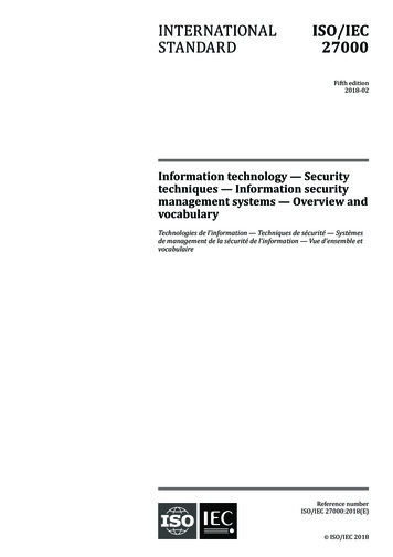
Select which TalkSwitch to use as the SIP network serverA multi-location SIP network requires a SIP server to manage calls across thenetwork. The SIP server contains registration information for all SIP devices inthe network. When making or receiving a VoIP call, a device will register with theSIP server, which will then route the call to the appropriate destination.TalkSwitch units have a built-in SIP server to manage a VoIP network. Thoughevery networked TalkSwitch unit has the capability, you must designate only oneTalkSwitch unit in a network as the SIP server.Note: For VoIP calls made through a VoIP service provider, the service providerwill act as the SIP Server.Which location and TalkSwitch system should I configure as the SIP server?Any TalkSwitch unit on the network can be designed to be the SIP server.To simplify network operation and reliability, we recommend that you choose alocation that has a static, rather than a dynamic public IP address. A static publicIP address does not change, providing a consistent connection address for eachlocation to communicate with the SIP server.If you do not have a static IP address, you can obtain a Fully Qualified DomainName (FQDN) from a Dynamic Domain Name Service (DDNS) provider. A DDNSmatches your dynamic IP addresses to your FQDN, so that your TalkSwitch VoIPnetwork operation is not affected by IP address changes.One DDNS provider is DynDNS; visit: http://www.dyndns.org/services/dns/dyndnsfor more information.Configuring TalkSwitch to act as the SIP server is described in STEP 2 of this guide— Configure TalkSwitch to act as the SIP Server.Example: Building on the previous example, the TalkSwitch system in theLondon office is designated as the SIP server — see Figure 3. When a locationinitiates a call, the TalkSwitch in London will resolve the destination addressfor the call, and coordinate a connection to route the call to its destination.HTTP://GLOBAL.TALKSWITCH.COM5
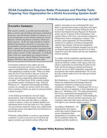
Assign phone numbers to each VoIP locationYou can now assign phone numbers to locations in your VoIP network.Each TalkSwitch unit with VoIP lines can support up to 12 VoIP phone numbers.Unique call handling scenarios can be configured for each VoIP number. VoIPphone numbers can be 3 or more digits in length.TalkSwitch supports 50 VoIP location numbers (250 to 299) that permit directdialing from any extension or Auto Attendant in the network. If needed, numbersoutside of this range can also be added — see TalkSwitch User Guide for details. EachVoIP phone number assigned in a multi-location network must be unique (i.e. onlyused for one location).For VoIP calls made through a VoIP service provider, the service provider willassign the VoIP numbers to be used for their service.To assist in assigning VoIP numbers for your network, use Appendix A — VoIPNetwork Administration Form at the end of this guide.Assigning VoIP phone numbers in your TalkSwitch configuration is described inSTEP 4 of this guide — Assign VoIP Phone Numbers.Example: Continuing with the previous example, five VoIP location numbersare assigned to VoIP lines in London (251 to 255), nine are assigned to VoIPlines in Sydney (261 to 269), and one is assigned to the teleworker officein Pretoria (271). These phone numbers can be dialed directly from anextension or from an Auto Attendant from any location within the network.FIGURE 3. TalkSwitch network configuration6TALKSWITCH VOIP NETWORK CONFIGURATION GUIDE
CONFIGURE TALKSWITCH TO MAKE AND MANAGE VoIP CALLSSTEP 1 — CONFIGURE TALKSWITCH IP ADDRESSESEach TalkSwitch system in a multi-location network must be configured with bothlocal IP and public IP address information. These addresses are used to direct VoIPcalls to the appropriate location. Each TalkSwitch unit in a system will have adifferent local IP address, and share a common public IP address.Set the TalkSwitch local IP addressThe following steps describe how to set the local IP address(es) of a TalkSwitchsystem:1. Open the TalkSwitch configuration software by double-clicking theTalkSwitch icon on your Desktop or, from the Windows Start menu, selectPrograms, the TalkSwitch folder, and click TalkSwitch.2. In the TalkSwitch System Configuration window, select System Information - IP Configuration from the menu at the left.3. TalkSwitch is factory configured to use DHCP (Dynamic Host ConfigurationProtocol) to automatically obtain its System IP Settings. If the location has aDHCP server, which is typically a function of the router, the fields on thescreen will automatically be filled in with the correct IP information. ClickUse the following IP and DNS information to ‘lock in’ these settings and ensurethey are saved as the system IP settings.4. If the location does not have a DHCP server, the System IP Settings fields willnot be filled in. Click Use the following IP and DNS information and enter theIP address(es), Subnet mask, Default Gateway, Preferred DNS Server, andAlternate DNS Server information in the appropriate fields. For details onthese settings, refer to the TalkSwitch User Guide.5. If there are multiple units in a system, enter the IP addresses of all units inthe system (Unit 2 IP Address, Unit 3 IP Address, Unit 4 IP Address). HTTP://GLOBAL.TALKSWITCH.COM 7
Set the TalkSwitch public IP addressThe public IP address of a TalkSwitch system is assigned by your Internet ServiceProvider. Depending on the type of service, you will either have a dynamic orstatic IP address. If you are unsure which type you have, contact your InternetService Provider.The following steps describe how to set the public IP address of a TalkSwitch system:1. Specify the Type of Public WAN IP for Internet Connection by selecting eitherdynamic or static from the drop-down list. For private networks, please ensurethe WAN IP address is the same as the Local IP address.If this TalkSwitch system will act as the SIP server for a network, werecommend having a static Public IP address. For more information on theSIP server, refer to Select which TalkSwitch to use as the SIP network server onpage 5.2. If this TalkSwitch system will act as the SIP server for a network and has adynamic Public IP address, enter the Fully Qualified Domain Name (FQDN)associated with the Public IP address. If the address is static, leave thisfieldblank.You can obtain a FQDN from a Dynamic Domain Name Service (DDNS) providersuch as DynDNS (visit http://www.dyndns.com/services/dns/dyndns). Checkyour router documentation to confirm which DDNS your router can support. 8TALKSWITCH VOIP NETWORK CONFIGURATION GUIDE
If using TalkSwitch with a VoIP Service Provider, proceed to STEP 6.STEP 2 — CONFIGURE TALKSWITCH TO ACT AS THESIP SERVERA multi-location TalkSwitch system requires that one (and only one) unit beconfigured to act as the SIP server (Redirect Proxy/Registrar). For information onthe SIP server, see Select which TalkSwitch to use as the SIP network server on page 5.To configure TalkSwitch to act as the SIP server:1. In the TalkSwitch System Configuration window, select SystemInformation - VoIP Configuration from the menu on the left.2. Select This TalkSwitch location is the Proxy/Registrar. The Public IP address orFully Qualified Domain Name will automatically be populated in the ProxyServer Name and Registrar Server Name fields.3. Leave the Outbound Proxy blank. In the Realm/Domain field, enter a name foryour network (example: abccompany).4. To enable authentication, select yes (digest) from the drop-down list belowRegistrar Authentication. Using authentication will allow only authorizeddevices to access the network.5. If Authentication has been enabled, enter a User/Account name (for example,ABC) and system Password.6. Information on reserving VoIP lines for each TalkSwitch unit is detailed inSTEP 3. HTTP://GLOBAL.TALKSWITCH.COM9
If using TalkSwitch with a VoIP Service Provider, proceed to STEP 6.STEP 3 — CONFIGURE TALKSWITCH TO REGISTERWITH THE TALKSWITCH SIP SERVERTo make and receive VoIP calls, TalkSwitch systems must be configured to registerwith the system designated as the SIP server. This step describes how to configurea TalkSwitch system to register with the SIP server.1. In the TalkSwitch System Configuration window, select System Information - VoIP Configuration from the menu on the left.2. Enter the Proxy Server Name and Registrar Server Name in the appropriatefields. These should be the same as those specified for the SIP server.3. Leave the Outbound Proxy blank. In the Realm/Domain field, enter a name foryour network (example: abccompany).4. If authentication was enabled for the SIP server, then enter the User/Accountname and system Password in the appropriate fields. These should be the sameas that specified for the SIP server.5. TalkSwitch provides options to reserve or limit the number of VoIP lines usedfor calls. For details, see next page. 10TALKSWITCH VOIP NETWORK CONFIGURATION GUIDE
Allocating VoIP linesTalkSwitch offers the flexibility to share VoIP lines with the TalkSwitch networkand a Service Provider. One can reserve lines for use with one or the otherdepending on requirements.To allocate VoIP resources, follow the following steps:1. From the System Information menu, select VoIP Configuration, then selectthe profile you wish to configure (e.g. TalkSwitch Profile or Service ProviderProfile).2. In the VoIP Lines area, select an upper limit (if required) for lines to use forthis profile. In the example below, 3 of the 4 available VoIP lines are allocatedto a TalkSwitch SIP network.3. If required, select the maximum number of VoIP lines to be used for incomingcalls. In the example below, all 3 of the permitted VoIP lines are selected.4. If required, select the maximum number of VoIP lines to be used foroutcoming calls. In the example below, 2 of the 3 permitted VoIP lines areselected. Each VoIP phone number can route over any of the permittedVoIPlines.Note: If no restrictions are selected, all VoIP lines will be permitted forincoming and outgoing calls. HTTP://GLOBAL.TALKSWITCH.COM11
If using TalkSwitch with a VoIP Service Provider, proceed to STEP 6.STEP 4 — ASSIGN VoIP PHONE NUMBERSThe following steps describe how to assign VoIP phone numbers. For informationon assigning VoIP phone numbers for a TalkSwitch VoIP network, see Assign phonenumbers to each VoIP location on page 6.To assign VoIP phone numbers:1. In the TalkSwitch System Configuration window, select System Information - VoIP Numbers from the menu on the left.2. Select VoIP 1 and check the Activate VoIP Number box, the default profile forentering a phone number is the TalkSwitch Profile.3. Enter a unique phone number to be used by callers dialing this TalkSwitchlocation. To simplify inter-branch calling between TalkSwitch locations, werecommend using the TalkSwitch VoIP location numbers 250-299, as thesenumbers can be directly dialed from any extension or from an Auto Attendant.Note: Ensure that each number assigned is unique in the network.For each TalkSwitch unit with VoIP lines on the network, you can assign up to12 VoIP phone numbers, increasing the number of inbound VoIP call handlingoptions available.4. Repeat the above steps for VoIP numbers 2-12.5. For systems with multiple units, repeat the process for each TalkSwitch unit(click on the tabs labeled TalkSwitch 1, TalkSwitch 2, TalkSwitch 3, andTalkSwitch 4). 12TALKSWITCH VOIP NETWORK CONFIGURATION GUIDE
STEP 5 — CONFIGURE CALL HANDLING FOR VoIP NUMBERSConfiguring call handling for VoIP numbers customizes TalkSwitch to fit theunique needs of your business. These call handling options are similar to theoptions available for your regular phone lines.Perform the following steps to configure VoIP call handling options for eachnetworked TalkSwitch unit with VoIP lines.1. In the TalkSwitch System Configuration window, select Call Handling - VoIPNumbers from the menu on the left.2. Select y
For information on the initial installation and setup of a TalkSwitch phone system, refer to the TalkSwitch Start Guide. For additional information on VoIP functionality and advanced configuration, refer to the TalkSwitch User Guide. Troubleshooting The TalkSwitch system and the configuration software are designed for ease of use.