Transcription
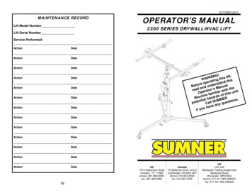
OCTOBER 2013MAINTENANCE RECORDLift Model NumberLift Serial NumberOPERATOR’S MANUAL2300 SERIES DRYWALL/HVAC LIFTService G this lift,RAWsngerati stand thipoerrBefo nd unde anual.adsMthere aator’witht.Oper familiar this unifeomsBeco l hazard NER.aiMtntionsSUsllepoteauqCnyave ahuif 7514 Alabonson RoadHouston, TX 77088phone: 281-999-6900fax: 281-999-6966Canada75 Saltsman Drive, Unit 5Cambridge, ON N3H 4R7phone: 519-653-5300fax: 519-653-5305UKUnit 16ABlackpole Trading Estate EastBlackpole RoadWorcester WR3 8SGphone: 011-44-1905-458333fax: 011-44-1905-458222
IndexOwner’s Responsibilities. 2Operator Safety Instructions . 3Operating Procedure .5-10Moving Lift to Work Area . 6Moving Lift with Load . 6Lifting and Lowering Loads. 7Attaching Cross Arms . 8Extending Load Rails. 8Load Support Hooks . 9Steering Handle . 9Back Up Brake. 10Storing and Transporting Lift . 10Specifications. 11Lift Diagram . 12Maintenance Instructions.13-14Troubleshooting . 15Maintenance Record. 16OWNER’S RESPONSIBILITIESThroughout this publication, the words WARNING, CAUTIONand IMPORTANT will be used to alert the user to specialinstructions concerning a particular operation that may behazardous if performed incorrectly or loadingCheck to make sure that theload does not exceed the 150lb/70 kilo load limit.Remove excess weight.Load may not be centeredproperly on the cradle.Check load capacity andreposition load.Slide pads obstructed. Inspecttracks for debris, grease, or anyforeign obstruction.Clean mast sections with adegreaser or brake cleaner andlubricate with a silicon lubricant.Inspect Lifting cable fordamage.If Lifting cable is cut, worn orfrayed, replace the cable.Slide pads are clean but mastsstill not sliding freely.Inspect mast sections for damage. Replace damaged mastsection.The brake on the winch orratchet dog are not installedcorrectly.Tighten lock nut on winch shaftdown completely, then back offone half turn.You have checked thewinch and the brake doesnot work at all.The brake ratchet or ratchet dogare not installed correctly or aredamaged and/or worn.Replace the worn or damagedcomponents.The winch is hard to crankdown.The brake is over-engagedRemove the load and turn thewinch handle counter clockwise.The brake will not disengageReplace the worn or damagedcomponents.Masts not rising insuccessionLoad is easing downslowlyOBSERVE THEM CAREFULLY !!WARNINGHazards or unsafe practices which could result insevere personal injury or death.If none of thesesolutions seem to fix theproblem.Call distributor’sCustomer Service Department.NOTE: Mast sections may rise out of succession when load is near maximumcapacity. If this occurs, the masts will correct themselves during continued use or whenthe load is removed from the cradle. Movement of the mast sections will not affect theposition of the load.CAUTIONHazards or unsafe practices which could result inminor personal injury, product or propertydamage.IMPORTANTIndicates information or instructions that arenecessary for proper operation and/ormaintenance.215
OPERATOR SAFETY INSTRUCTIONSGeneral Maintenance:1.Check the winch handle for wear or bends.IMPORTANT2.Examine all bolts and nuts to be sure they are tight.3.Legs, cross arms, rails, load hooks, masts and base should be dent freeand damage free.Read and understand Operators Manual beforeusing Lift.4.Check damage (indentations) which can restrict the movement of the mastsections.5.Check legs by rotating them into each position to check locking mechanism.6.Inspect masts and hold-down device.7.Raise mast sections to inspect for free, smooth sliding action. Make sureslide pads are free of dust and debris and spray a light coat of silicone lubrication on slide pads.8.Make sure caster wheels rotate freely and are undamaged.9.Check to be sure that all mast covers are attached to the lift.Inspect cable before each use. Do not use if cableis frayed, worn, cut, burnt or otherwise damaged.Use only on solid level surface. Keep work areaclean and clear of clutter and debris.Test load balance before lifting. Do not use withoutproperly locking legs. Never exceed rated loadcapacity. Never lift more than one sheet ofdrywall at a time.WARNINGReplace all worn or damaged parts only withSumner parts.Stay clear of overhead wires and obstructions.Never operate in gusty winds. Lifting loads duringhigh winds can result in the lift tipping over and thepossibility of operator injury.WARNINGModifying the lift in any way can cause injury ordeath!Do not stand under an elevated load.Never leave lift unattended with an elevated load.143
MAINTENANCE INSTRUCTIONSDo not use to lift personnel. Do not sit or stand onlift.Before each use:1.Do not climb on mast or put a side load on mast.Do not use unit to support ladders for climbing orhoisting.2.3.4.Inspect the lifting cable for frays, cuts or burns. If any damage is visibleon the lifting cable, do not use the lift.Make certain winch operates freely and lifting cable is not tangled on thewinch drum.Check cradle assembly, legs, masts and base for bends.Make sure caster wheels move freely.Recommended Inspection Every 6 Months:Do not use unit outside in thunder, lightning, orsevere weather.1.2.Wear proper clothing. Hard hat, safety shoes andgloves should be worn as a precaution whenoperating this lift.Inspect the lifting cable for frays, cuts or burns. If any damage is visibleon the lifting cable, do not use the lift.Make certain winch works freely and that there are no loose or damagedparts.Winch Maintenance:1.2.Be sure that the winch cover is on the winch.Check ratchet dogs and brake ratchet for wear. If any wear is visible,replace the components. If not, lubricate both parts with a light oil.For proper brake adjustment see “Troubleshooting” section on page 15.Avoid horseplay around equipment, and keep bystanders at asafe distance. Do not allow children to operate this unit andalways keep them out of work areas.3.1.2.Lower the masts to engage the safety latch.Remove the large gear cover from the winch.Do not misuse the lift. Perform only the functions for which thelift was designed.3.Disconnect the cable from the winch drum. Make note of thedirection the cables are wrapped around the drum.Remove the cradle assembly from on top of the lift.Remove the mast assembly and lay it down flat on a work surface.Extend the center mast up until the six allen head screws are exposed.Remove the six allen head screws.Slide the center and upper mast out the bottom of the outer mast.Re-reeve the new cable through the lift using the existing cable as aguide.Attach cable to winch drum making sure cable are wrapped in properdirection. Note: The cable must be wrapped in the direction noted instep 3.Wind the slack cable tightly and evenly across the load drum.Replace the center and upper mast sections into the outer mast.Replace the six allen head screws.Replace the winch cover.Never use two lifts in tandem to lift a load that exceeds thecapacity of a single lift.Prior to each use of the unit, inspect all moving parts and thelifting cable to ensure they are in proper working condition.Replacing the Lifting Cable:4.5.6.7.8.9.10.11.12.13.14.413
OPERATING PROCEDURELIFT DIAGRAM1. Assembling DrywallLiftMastLoad Support HookCross ArmBaseCradle AssemblyCradleYour 2300 series Drywall lift will arrive in three sections, theBase, the Mast and the Cradle. Complete assembly will takeless than five minutes.Top MastCenter MastLift RailWinchAssemblyOuter MastTo assemble your lift, firstopen the legs on the baseassembly to their operatingposition. Make sure thespring loaded plungers arefully engaged and the legsare locked securely intoposition. Next, place themast assembly firmly intothe base. Make sure themast locating ring is firmlyseated onto the base locating post.Base AssemblyBase LegBackup BrakeMast locating ringCaster125Locatingpost
frontSPECIFICATIONSFinally, place the cradle assemblyonto the mast. Ensure that the cradleis locked to the mast with the lockingpin and that it is facing the properdirection.2311Lockingpin2. Moving Lift to Work Area(No Load)The lift is normally moved to the job site by rolling on its 4”casters using the steering handle. Note: Do not pull by theload lifting cable.Steering handle3. Moving Lift in Work Area (With Load)Although it is best to move the unit to thejob site unloaded, light loads may betransported as long as the unit is rolledon the casters on a level surface. Alwayshave the load in the lowest possibleposition before moving the unit.If it is necessary to move the unit with anelevated load: Make sure the area is clear of obstructions Keep personnel away from the load and behind theoperator’s position Move the unit slowly, avoiding sudden jerky starts and stops Make sure the load is secure and properly balancedCAUTIONIf a load is being transported, it should be securedto the cradle to avoid shifting.WARNINGMoving the unit with elevated loads should becontained to short distances; i.e., 10-15 feet/4-5meters.6DimensionsHeight Operating231563”160 cm75”WeightNet Weight99 lb45 kg99 lb45 kgLoad CapacityLoad Capacity (13" L.C.)150 lb70 kg150 lb70 kgLength OperatingBase WidthGround ClearanceLoad Height (minimum)Load Height (maximum)190.5cm52”132 cm52”132 cm55” 139.7 cm55”139.7cm1.5”3.8 cm1.5”3.8 cm34”86 cm48”122 cm11' 2-3/4”14'9-3/4”3.4 m4.5 mNumber of Cables11Drywall Cradle SpecificationsCradle Length (max)119”Cradle Length (min)49”Cradle Width41”302.3 cm124.5 cm104.1 cmHVAC Cradle SpecificationsCradle Length (max)29”Cradle Length (min)16”Cradle Width34”73.7 cm40.0 cm86.4 cm11
9. Back Up Brake4. Lifting and Lowering LoadsThe 2300 series drywall lift isoutfitted with a “Back Up Brake.”This stops the lift from rollingbackward when working up againsta wall or ceiling. To engage thebrake, simply press down on it withyour foot. This will release thebrake. The brake will now preventthe lift from rolling backward. Toplace the brake back into thestored position, lift it upwith your foot until itlocks onto the rear leg.raiseUse the winch to crank mast up ordown into the desired position.Any unstable load must be balancedand secured to the cradle prior tolifting.Turn winch crank clockwise toelevate the load, while watching for overhead standard obstructions. Turn winch handle counter clockwiseto lower the load.Each handle is equipped with twomounting positions. With the handlesmounted in the “standard” position, theoperator can raise and lower loads asnormal. With the handles mounted in the“high speed” position, the operator canraise and lower the lift in half the time.high speed10. Storing and Transporting the LiftThe 2300 series lift is designed for easytransport. The unit is easily broken downinto three sections. Allthree sections are easy tocarry. The main masteven has a carrying handlecentrally located. Prior totransporting the mainmast, attach the mast holddown cable to prevent themasts from extending unintentionally.CAUTIONMake sure the floor surface is level.WARNINGNo riders allowed on this unit. This isnot a personnel lift and never should beused for hoisting or moving people.Mast Latch107
cross arm5. Attaching Cross Armsload railThe cross arms arrive on the cradle assemblyin the storage position. To place the cross arms in theiroperating positions, pull the ringon the spring loaded plungerand remove from the storagebar. Position the cross armover one of the operatingpositions and drop down intoplace ensuring that the springloaded plunger has fullyengaged in the locating hole.7. Load Support HooksTo position the load supporthooks in the operating position,pull the ring on the springloaded plunger and rotate thehook from the stowed position.Ensure that the spring loadedplunger is fully engaged prior toloading drywall onto the lift.Never attempt to lift a sheet ofdrywall without positioning theload support hooks into theoperating position.load support hookWARNINGThe spring loaded plunger must be fully engagedprior to loading drywall onto the lift.CAUTIONThe load support hook should be positioned on theside of the lift opposite the winch.WARNINGAttempting to lift a sheet of drywall with using theload support hooks can result in injury.6. Extending Load RailsThe load rails can be extendedto help support wide loads. Toextend the rails, pull the ring onthe spring loaded plunger andslide the rail out. The springloaded plunger will engage in thenext available position.WARNINGThe spring loaded plunger must be fully engagedprior to lifting a load.WARNINGAttempting to lift more than one sheet of drywall canresult in injury.8. Steering HandleThe 2300 series lift comes equipped with a steering handle. Thishandle aids the operator in positioning the lift during operation.To position the handle, pull out (approximately 1 in. (2.5 cm))past the stop block androtate up 90 degrees. Release thehandle and it will lock in place.Reverse this procedure for storage.WARNINGNever lift a load without ensuring it is properlybalance and supported on the cradle.89
Drywall Cradle Specifications Cradle Length (max) 119” 302.3 cm Cradle Length (min) 49” 124.5 cm Cradle Width 41” 104.1 cm Cradle Length (max) 29” 73.7 cm Cradle Length (min) 16” 40.0 cm Cradle Widt