Transcription
Titan PlusElectrophoresis Power SupplyOperator’s ManualCat. No. 1504, 110 VacCat. No. 1505, 220 Vac
These symbols may be used on the instrument.Caution, electric shock hazard, high voltages capable of causing personalinjury - shut down the instrument and unplug the power cord before touching- do not operate with the cover(s) removedCaution, heat hazard - allow heated components to cool before handling.Caution, general hazard - see precautions and hazards (sections 3 and 4) ofOperator’s Manual before proceedingDirect currentAlternating currentBoth direct and alternating currentGround (earth) terminalProtective conductor terminal (grounded conductors)Frame or chassis terminalEquipotentiality (conductor with all parts at a single potential)On (power switch)Off (power switch)Equipment protected throughout by double insulation or reinforced insulation(equivalent to Class II of IEC 536)-i-
Titan Plus Power SupplyOperator’s ManualContentsONE - Instrument Use and Function .1TWO - Principles of Operation .2THREE - Precautions and Limitations.3FOUR - Hazards.4FIVE - Description .55.1. Contols.55.2. Displays .5SIX - Installation Instructions .66.1. Unpacking and Inspection.66.2. Installation.6SEVEN - Operating Instructions .77.1. Start Electrophoresis.77.2. Monitor Output .87.3. Unlimited Time .87.4. Stop Run .8EIGHT - Test Functions and Quality Control .9NINE - Performance Specifications .10TEN - Maintenance, Troubleshooting, and Warranty.1210.1. Maintenance .1210.2. Troubleshooting .1310.3. Waranty .14-ii-
ONE - Instrument Use and FunctionThe Titan Plus Power Supply is intendedfor use with all standard electrophoresischambers. It can be used with allelectrophoretic media including celluloseacetate, agar, starch, acrylamide andagarose support media. The powersupply provides controlled voltage,variable current output with automatic ormanual timing. It is for in-vitro diagnosticuse in a laboratory or similar environment.1
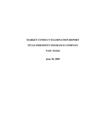
TWO - Principles of Operationautomatically cuts off power to the outputjacks when time remaining reaches zero.When Hold is selected, the timer isbypassed so that the operator times andturns off electrophoresis power manually.The functional units of the Titan PlusPower Supply are shown in Figure 1.User input is received from variouscontrols on the instrument front. The userselects the output voltage and theelectrophoresis time for automatic timingor bypassing the internal timer, anddetermines the information shown on thedisplay.When a run has been started, the VoltageAdjust Knob sets an auto-transformer todetermine the output voltage produced bythe high-voltage power supply. The highvoltage power supply output is measuredby a meter and displayed according to theposition of the Display Select Switch.Voltage is measured and displayed in oneposition, or current at right or left jacks ismeasured and displayed in otherpositions. The display has its own powersupply.An electromechanical timer is used forstarting the run and for automatic timing.The timer can be bypassed, depending onthe position of the Hold/Normal Switch.When Normal is selected, theelectrophoresis time is selected on theTime knob, setting the electromechanicaltimer and starting the run. The timerFig. 1. Functional Block Diagram of Titan Plus Power Supply.2
THREE - Precautions and Limitations3.1. The entire operator’s manual shouldbe read and understood before attemptinginstrument operation.3.2. Installation is to be performed by theoperator.3.3. Provide adequate room at the sidesand back of the instrument for good aircirculation.3.4. No harsh cleansers, acids, or basesshould be used or spilled on inner or outersurfaces. Do not immerse the unit.ALWAYS UNPLUG THE MAIN POWERCORD BEFORE CLEANING.Should an instrument be contaminated byblood or blood derivative, spray anycontaminated surface with a commercialvirucidal and germicidal agent. Observewhere the specimens are used inside theinstrument and confine cleaning to thatarea. Wipe up the residue. Thesematerials contain alcohol and alcohol is acorrosive to metal surfaces.3.5. Before an electrophoresis run,ensure that the chamber polarity iscorrect, that the buffer tanks are filled tothe correct level, and that the sampleplates are oriented correctly.3
FOUR - Hazards4.1. If the instrument is used in a mannernot specified by this manual, theprotection provided by equipment designmay be impaired.4.2. This device contains very highvoltages which can be extremelydangerous. Safeguards are built into theinstrument to prevent user contact withhigh voltages, however, ALWAYS TURNOFF THE POWER, DISCONNECT THEMAIN POWER CORD, AND USEEXTREME CARE when attemptingdisassembly for cleaning, repair, oradjustments. Do not operate anyinstrument with the cover removed unlessinstructed to do so by a qualified servicetechnician directly representing HelenaLaboratories, its subsidiaries, or itsdistributors.4.3. Do not attempt to operate theinstrument without plugging the powercord into a grounded wall outlet of theproper voltage and frequency. Thisinformation is contained on the serialnumber plate located on the back of theinstrument.4.4. For emergency shut down,disconnect the power supply’s power cordfrom the wall outlet or turn off the powerusing the On/Off switch.4
FIVE - Description5.1. ControlsPOWER ON/OFF Switch: The powerswitch is located on the front panel andcontrols power to the instrument.TIME Dial: In normal (internally timed)mode (see below), turn the dial counterclockwise to set the electrophoresis runtime, turning on the power to start the run.HOLD/NORMAL Switch: NORMAL forautomatic timing, HOLD to turn on powerand bypass the internal timer.VOLTAGE ADJUST Knob: Turn untildesired output voltage is displayed.DISPLAY SELECT Switch: Voltageposition to display output voltage of alljacks. Set at OUTPUT CURRENT LEFTor RIGHT to display the output current(mA) of the respective output jacks.5.2. DisplayThree-character LED display showselectrophoresis voltage with DisplaySelect switch set for VOLTAGE, or outputcurrent of either left or right output jackswhen the display select switch is set atOUTPUT CURRENT LEFT or RIGHT.5
SIX - Installation Instructions1. Select an environment free ofexcessive humidity and dust, and largetemperature fluctuations. Ambienttemperature should not be above 86oF(30oC) or below 59oF (15oC).WARNING: Read Section Three(Precautions and Limitations) and SectionFour (Hazards) before attemptinginstallation or operation.6.1. Unpacking and Inspection2. Place the power supply on a level, flatsurface. Make sure that there is enoughspace behind and around it to allow goodair circulation.1. Check all shipping containers for signsof damage. If damage is found,immediately notify the shipping carrier.3. Plug the female end of the line powercord into the receptacle in the back panelof the instrument.2. Carefully unpack the instrument andaccessories and remove them from theshipping cartons. The packing materialshould be removed undamaged, ifpossible, should repacking be necessary.4. Plug the other end of the power cordinto a grounded wall outlet of the propervoltage and frequency (check the serialnumber plate on the back of theinstrument for this information). The walloutlet should not be on the same circuit asany large load device such as arefrigerator, compressor, centrifuge, etc.The instrument’s circuitry contains filters toreduce the effect of line voltagefluctuations; however, they should still beavoided. If the operator experiencesdifficulty, it may be necessary to install anisolation transformer.3. Remove plastic wrappings from theinstrument and accessories. If scissors ora knife are used to cut the plastic orbinding tape, take care not to scratch theinstrument.4. Inspect the instrument for any obvioussigns of damage. If damage is found,notify the shipping carrier and HelenaLaboratories.5. Inventory all items: If any parts aremissing, recheck the packing materialsbefore notifying Helena Laboratories.Table 6-1. Inventory.1 Titan Plus Power Supply1 Power Cord1 Fuse1 Operator’s Manual6.2. InstallationNOTE: The Titan Plus Power Supply is a“Category II” device under EN 61010-1and is for use in a laboratory or similarenvironment.6
SEVEN - Operating Instructions9. Turn the TIME dial clockwise to thedesired electrophoresis duration forautomatic timing.7.1. To Start Electrophoresis1. Turn the VOLTAGE ADJUST knob fullycounter-clockwise (to the minimumsetting).At the end of the run, a been will soundand power will be turned off. The displaywill return to 000.2. Put the DISPLAY SELECT switch inthe VOLTAGE (center) position.10. Turn the VOLTAGE ADJUST knobfully counter-clockwise (minimum voltage)and remove the leads from the powersupply.3. Turn on the POWER switch (located onthe front panel). The display should ready000. If it does not, turn the TIMERcompletely clockwise to turn the timer off.If the display does not come on, refer tothe troubleshooting table in Section 10.4. Prepare the chamber(s) as instructedby the appropriate electrophoresisprocedure supplied with the reagent kit.5. Connect the positive and negativeleads into the electrophoresis chamber(s),making sure that the display reads 000.This insures that no voltage is applied tothe output circuit.6. Connect the leads to the plugs in thefront or back of the power supply. Useonly one left and one right set of outputjacks at a time. Make sure that thepolarities at each end of the leads match.Check the electrophoresis chamber forcorrect cable polarity, proper buffer level,and correct membrane or plate orientation.7. With the HOLD/NORMAL switch atNORMAL, turn the TIME dial counterclockwise past the desired electrophoresistime.NOTE: The run is now in progress.8. Quickly turn the VOLTAGE ADJUSTknob clockwise until the desired voltage isdisplayed.7
SEVEN - Operating Instructions7.2. Monitor OutputTo monitor output during a run, move theDISPLAY SELECT switch.In the VOLTAGE position, voltage at theoutput terminals is displayed in 1 V units.To view current flowing in the chamber(s),move the switch to the appropriateOUTPUT CURRENT LEFT or RIGHTposition, then return it to the centralVOLTAGE position. The current isdisplayed in 1 mA units.7.3. Unlimited TimeTo bypass the timer for any reason, followthe steps 1 to 6 in 7.1, above, and put theHOLD/NORMAL switch in the HOLDposition, turning on the power.To end the run, make sure that the timer isturned off and put the HOLD/NORMALswitch in the NORM position.7.4. Stop RunTo stop the run, turn the TIME dial fullyclockwise. A beep will sound and powerwill be cut off. The display will return to000. Turn the VOLTAGE ADJUST knobfully counter-clockwise (minimum voltage)and remove the leads from the powersupply.8
EIGHT - Test Functions and Quality Control8.1. Test FunctionsNo operator adjustments are possible.Only a qualified electronics technician cancheck and adjust timer accuracy andoutput voltage or current levels.8.2. Quality ControlRun an appropriate Helena Laboratoriescontrol with all patient samples.9
NINE - Performance SpecificationsTimingAutomatic or ExternalInput Power, Cat. No. 1504Input Power, Cat. No. 1505110 Vac, 50/60 Hz, 110 W (max.)220 Vac, 50/60 Hz, 110 W (max.)Voltage Output Range0 to 650 Vdc /- 3 V in 1 V incrementsCurrent Output Range0 to 120 mA /- 2 mA in 1 mA incrementsTimer1 minute to 60 min., 1 min. incrementsFuse, 110 V unitFuse, 220 V unit1 A, 250 V slow blow0.5 A, 250 V slow blowDimensions (Approximate)5.5 in. (14 cm) high9.5 in. (24 cm) wide10 in. (25 cm) deepWeight11 lb (5 kg)End of Run AlarmAudible signal, approximately 6 secondsChambersAccepts all standard chambersSupport MediaAll electrophoretic media, including cellulose acetate, agarose, acrylamide andstarch10
NINE - Performance SpecificationsThese symbols may be used on the instrument.Caution, electric shock hazard, high voltages capable of causing personalinjury - shut down the instrument and unplug the power cord beforetouching - do not operate with the cover(s) removedCaution, heat hazard - allow heated components to cool before handling.Caution, general hazard - see precautions and hazards (sections 3 and 4)of Operator’s Manual before proceedingDirect currentAlternating currentBoth direct and alternating currentGround (earth) terminalProtective conductor terminal (grounded conductors)Frame or chassis terminalEquipotentiality (conductor with all parts at a single potential)On (power switch)Off (power switch)Equipment protected throughout by double insulation or reinforcedinsulation (equivalent to Class II of IEC 536)11
TEN - Maintenance, Troubleshooting, WarrantyNo harsh cleansers, acids, or basesshould be used or spilled on inner or outersurfaces. Do not immerse the unit.ALWAYS UNPLUG THE MAIN POWERCORD BEFORE CLEANING.10.1. Maintenance1. Inspect the electrophoresis cables forcracks and nicks in the insulation at leastmonthly. Replace defective cables.Should an instrument be contaminated byblood or blood derivative, spray anycontaminated surface with a commercialvirucidal and germicidal agent. Observewhere the specimens are used inside theinstrument and confine cleaning to thatarea. Wipe up the residue. Thesematerials contain alcohol and alcohol is acorrosive to metal surfaces.2. To replace a blown fuse:1) Turn off the power.2) Unplug the power cord.3) Use a small screwdriver to pryout the fuse cartridge using the tab in theplug socket.4) Lift up the locking tab on thefusecartridge (extends beyond the rest of thecartridge) and pull out the fuse holder.5) Pull out the old fuse and replaceit with one of the proper rating (1 A/250 VSB for 110 V unit, 0.5 A/250 V SB for 220V unit).Dry the power supply completely beforeplugging the power cord back in andturning on the power.WARNING: For continued protection fromfire hazard, use only fuses of the sametype and rating specified.6) Push the fuse holder back intothe cartridge (line up the notch in theholder with the locking tab) until it snaps inplace.7) Push the fuse cartridge backinto the housing so that the exposed fuseend enters first and the small tab fits intothe notch at the bottom of the power cordsocket.8) Plug the power cord back intothe wall outlet and turn on the power.If the fuse fails again, turn off the powerand contact Helena Laboratories forassistance.3. Clean spills with a soft damp cloth onlyafter turning off the power and unpluggingthe power cord.12
TEN - Maintenance, Troubleshooting, Warranty10.2. TroubleshootingRefer to the table below for troubleshooting. Contact Helena Laboratories forassistance should the suggested solutions not correct a problem.ProblemPossible CauseSolutionDisplay does not come onafter power onInstrument not plugged into walloutlet or cord not plugged intoinstrumentPlug in power cord firmly atboth endsFuse BlownReplace fuseDisplay comes on but nooutputTimer is not onSet the timerUnable to obtain desiredvoltageSelected voltage betond instrument rangeReset voltageBad electrical connectionCheck for proper connectionof leads, check for damaged lead insulationImproper chamber set upCheck for correct plate orientation, adequate bufferlevel, correct bufferBad electrical connectionCheck for proper connectionof leads, check for damgedlead insulationImproper chamber set upCheck for correct plate orientation, adequate bufferlevel, correct buffer, checkbuffer concentration, makesure wicks contact bothbuffer and support media,check purity of water sourceCurrent readings lower thannormal13
TEN - Maintenance, Troubleshooting, Warranty10.3. WarrantyHelena Laboratories warrants its productsto meet Helena’s published specificationsand to be free from defects in materialsand workmanship. Helena’s liability underthis contract or otherwise shall be limitedto replacement or refund of any amountnot to exceed the purchase priceattributable to the goods as to which suchclaim is made. These alternatives shall bethe buyer’s exclusive remedies.In no case will Helena Laboratories beliable for consequential damages even ifHelena has been advised as to thepossibility of such damages.The foregoing warranties are in lieu of allwarranties expressed or implied, including,but not limited to, the implied warranties ofmerchantability and fitness for a particularpurpose.For additional information, call HelenaLaboratories at 800-231-5663 toll free.Helena LaboratoriesPO BOX 752Beaumont, TX 77704-0752 March 2008Helena LaboratoriesD6500002D03/0814
1 Titan Plus Power Supply 1 Power Cord 1 Fuse 1 Operator's Manual 6.2. Installation NOTE: The Titan Plus Power Supply is a "Category II" device under EN 61010-1 and is for use in a laboratory or similar environment. 1. Select an environment free of excessive humidity and dust, and large temperature fluctuations. Ambient