Transcription
CHAPTER34Images34-1 IMAGES AND PLANE MIRRORSLearning ObjectivesAfter reading this module, you should be able to . . .34.01 Distinguish virtual images from real images.34.02 Explain the common roadway mirage.34.03 Sketch a ray diagram for the reflection of a pointsource of light by a plane mirror, indicating the objectdistance and image distance.34.04 Using the proper algebraic sign, relate the objectdistance p to the image distance i.34.05 Give an example of the apparent hallway that you cansee in a mirror maze based on equilateral triangles.Key Ideas An image is a reproduction of an object via light. If theimage can form on a surface, it is a real image and can existeven if no observer is present. If the image requires the visualsystem of an observer, it is a virtual image. A plane (flat) mirror can form a virtual image of a lightsource (said to be the object) by redirecting light rays emerging from the source. The image can be seen where backwardextensions of reflected rays pass through one another. Theobject’s distance p from the mirror is related to the (apparent)image distance i from the mirror byi ! "p(plane mirror).Object distance p is a positive quantity. Image distance i for avirtual image is a negative quantity.What Is Physics?One goal of physics is to discover the basic laws governing light, such as the lawof refraction. A broader goal is to put those laws to use, and perhaps the mostimportant use is the production of images. The first photographic images, made in1824, were only novelties, but our world now thrives on images. Huge industriesare based on the production of images on television, computer, and theaterscreens. Images from satellites guide military strategists during times of conflictand environmental strategists during times of blight. Camera surveillance canmake a subway system more secure, but it can also invade the privacy of unsuspecting citizens. Physiologists and medical engineers are still puzzled by how images are produced by the human eye and the visual cortex of the brain, but theyhave managed to create mental images in some sightless people by electricalstimulation of the brain’s visual cortex.Our first step in this chapter is to define and classify images. Then we examine several basic ways in which they can be produced.Two Types of ImageFor you to see, say, a penguin, your eye must intercept some of the light raysspreading from the penguin and then redirect them onto the retina at the rear ofthe eye. Your visual system, starting with the retina and ending with the visualcortex at the rear of your brain, automatically and subconsciously processes theinformation provided by the light. That system identifies edges, orientations,1010
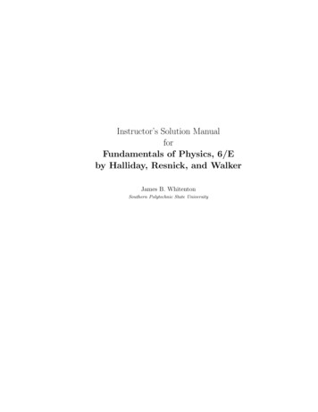
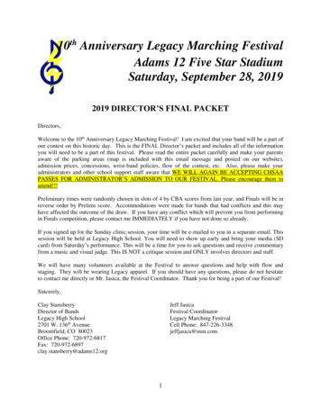
101134-1 I MAG ES AN D PL AN E M I R RORStextures, shapes, and colors and then rapidly brings to your consciousness animage (a reproduction derived from light) of the penguin; you perceive and recognize the penguin as being in the direction from which the light rays came andat the proper distance.Your visual system goes through this processing and recognition even if thelight rays do not come directly from the penguin, but instead reflect toward youfrom a mirror or refract through the lenses in a pair of binoculars. However, younow see the penguin in the direction from which the light rays came after theyreflected or refracted, and the distance you perceive may be quite different fromthe penguin’s true distance.For example, if the light rays have been reflected toward you from a standardflat mirror, the penguin appears to be behind the mirror because the rays youintercept come from that direction. Of course, the penguin is not back there. Thistype of image, which is called a virtual image, truly exists only within the brainbut nevertheless is said to exist at the perceived location.A real image differs in that it can be formed on a surface, such as a card or amovie screen. You can see a real image (otherwise movie theaters would beempty), but the existence of the image does not depend on your seeing it and it ispresent even if you are not. Before we discuss real and virtual images in detail,let’s examine a natural virtual image.A Common MirageA common example of a virtual image is a pool of water that appears to lie on theroad some distance ahead of you on a sunny day, but that you can neverreach. The pool is a mirage (a type of illusion), formed by light rays coming fromthe low section of the sky in front of you (Fig. 34-1a). As the rays approach theroad, they travel through progressively warmer air that has been heated bythe road, which is usually relatively warm. With an increase in air temperature,the density of the air — and hence the index of refraction of the air — decreasesslightly. Thus, as the rays descend, encountering progressively smaller indexes ofrefraction, they continuously bend toward the horizontal (Fig. 34-1b).Once a ray is horizontal, somewhat above the road’s surface, it still bends becausethe lower portion of each associated wavefront is in slightly warmer air and is movingslightly faster than the upper portion of the wavefront (Fig. 34-1c). This nonuniformmotion of the wavefronts bends the ray upward. As the ray then ascends, it continuesto bend upward through progressively greater indexes of refraction (Fig. 34-1d).If you intercept some of this light, your visual system automatically infersthat it originated along a backward extension of the rays you have interceptedand, to make sense of the light, assumes that it came from the road surface. If thelight happens to be bluish from blue sky, the mirage appears bluish, like water.Because the air is probably turbulent due to the heating, the mirage shimmies, asif water waves were present. The bluish coloring and the shimmy enhance theillusion of a pool of water, but you are actually seeing a virtual image of a lowsection of the sky. As you travel toward the illusionary pool, you no longer intercept the shallow refracted rays and the illusion disappears.WarmLight rayFastWarmerPool re 34-1 (a) A ray from a low section of the sky refracts through air that is heated by a road (without reaching the road). An observer whointercepts the light perceives it to be from a pool of water on the road. (b) Bending (exaggerated) of a light ray descending across an imaginary boundary from warm air to warmer air. (c) Shifting of wavefronts and associated bending of a ray, which occur because the lower ends ofwavefronts move faster in warmer air. (d) Bending of a ray ascending across an imaginary boundary to warm air from warmer air.
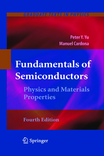
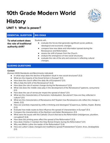
1012CHAPTE R 34 I MAG ESPlane MirrorsIn a plane mirror the lightseems to come from anobject on the other side.MirrorIOθθpiFigure 34-2 A point source of light O, calledthe object, is a perpendicular distance pin front of a plane mirror. Light raysreaching the mirror from O reflect fromthe mirror. If your eye intercepts some ofthe reflected rays, you perceive a pointsource of light I to be behind the mirror,at a perpendicular distance i. The perceivedsource I is a virtual image of object O.OpiθbθθθIaMirrorFigure 34-3 Two rays from Fig. 34-2. RayOa makes an arbitrary angle u with thenormal to the mirror surface. Ray Ob isperpendicular to the mirror.OMirrorA mirror is a surface that can reflect a beam of light in one direction instead ofeither scattering it widely in many directions or absorbing it. A shiny metalsurface acts as a mirror; a concrete wall does not. In this module we examine theimages that a plane mirror (a flat reflecting surface) can produce.Figure 34-2 shows a point source of light O, which we shall call the object, at aperpendicular distance p in front of a plane mirror. The light that is incidenton the mirror is represented with rays spreading from O. The reflection of thatlight is represented with reflected rays spreading from the mirror. If we extendthe reflected rays backward (behind the mirror), we find that the extensionsintersect at a point that is a perpendicular distance i behind the mirror.If you look into the mirror of Fig. 34-2, your eyes intercept some of thereflected light. To make sense of what you see, you perceive a point source oflight located at the point of intersection of the extensions. This point source is theimage I of object O. It is called a point image because it is a point, and it is a virtual image because the rays do not actually pass through it. (As you will see, raysdo pass through a point of intersection for a real image.)Ray Tracing. Figure 34-3 shows two rays selected from the many rays inFig. 34-2. One reaches the mirror at point b, perpendicularly. The other reaches itat an arbitrary point a, with an angle of incidence u. The extensions of the two reflected rays are also shown. The right triangles aOba and aIba have a commonside and three equal angles and are thus congruent (equal in size); so their horizontal sides have the same length. That is,IaIb ! Ob,(34-1)where Ib and Ob are the distances from the mirror to the image and the object,respectively. Equation 34-1 tells us that the image is as far behind the mirror asthe object is in front of it. By convention (that is, to get our equations to workout), object distances p are taken to be positive quantities and image distances ifor virtual images (as here) are taken to be negative quantities. Thus, Eq. 34-1 canbe written as i ! p or asi ! "p(plane mirror).(34-2)Only rays that are fairly close together can enter the eye after reflection at amirror. For the eye position shown in Fig. 34-4, only a small portion of the mirrornear point a (a portion smaller than the pupil of the eye) is useful in forming theimage. To find this portion, close one eye and look at the mirror image of a smallobject such as the tip of a pencil. Then move your fingertip over the mirror surface until you cannot see the image. Only that small portion of the mirror underyour fingertip produced the image.Extended ObjectsIn Fig. 34-5, an extended object O, represented by an upright arrow, is atperpendicular distance p in front of a plane mirror. Each small portion of theFigure 34-4 A “pencil” of rays from O entersthe eye after reflection at the mirror. Onlya small portion of the mirror near a isinvolved in this reflection. The light appearsto originate at point I behind the mirror.pOiIIn a plane mirror the imageis just as far from the mirroras the object.Figure 34-5 An extended object O and its virtual image I in a plane mirror.
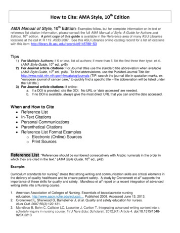
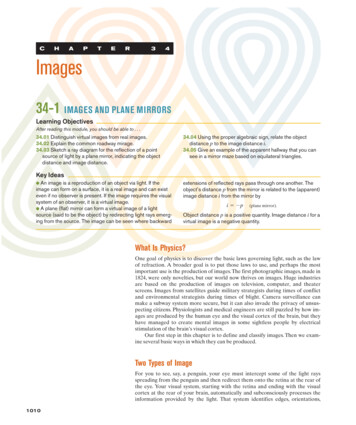
101334-1 I MAG ES AN D PL AN E M I R RORSFigure 34-6 A maze ofmirrors.Courtesy Adrian Fisher, www.mazemaker.comAobject that faces the mirror acts like the point source O of Figs. 34-2 and 34-3.If you intercept the light reflected by the mirror, you perceive a virtual image Ithat is a composite of the virtual point images of all those portions of the object. This virtual image seems to be at (negative) distance i behind the mirror,with i and p related by Eq. 34-2.We can also locate the image of an extended object as we did for a pointobject in Fig. 34-2: we draw some of the rays that reach the mirror from the top ofthe object, draw the corresponding reflected rays, and then extend those reflectedrays behind the mirror until they intersect to form an image of the top of theobject. We then do the same for rays from the bottom of the object. As shown inFig. 34-5, we find that virtual image I has the same orientation and height (measured parallel to the mirror) as object O.(a)OBB(b)OMirror MazeIn a mirror maze (Fig. 34-6), each wall is covered, floor to ceiling, with a mirror.Walk through such a maze and what you see in most directions is a confusing montage of reflections. In some directions, however, you see a hallway that seems to offer a path through the maze.Take these hallways, though, and you soon learn, aftersmacking into mirror after mirror, that the hallways are largely an illusion.Figure 34-7a is an overhead view of a simple mirror maze in which differentlypainted floor sections form equilateral triangles (60 angles) and walls arecovered with vertical mirrors. You look into the maze while standing at point O atthe middle of the maze entrance. In most directions, you see a confusing jumbleof images. However, you see something curious in the direction of the ray shownin Fig. 34-7a. That ray leaves the middle of mirror B and reflects to you at themiddle of mirror A. (The reflection obeys the law of reflection, with the angle ofincidence and the angle of reflection both equal to 30 .)To make sense of the origin of the ray reaching you, your brain automatically extends the ray backward. It appears to originate at a point lying behindmirror A. That is, you perceive a virtual image of B behind A, at a distance equalto the actual distance between A and B (Fig. 34-7b). Thus, when you face into themaze in this direction, you see B along an apparent straight hallway consisting offour triangular floor sections.This story is incomplete, however, because the ray reaching you does notoriginate at mirror B — it only reflects there. To find the origin, we continue toapply the law of reflection as we work backwards, reflection by reflection on themirrors (Fig. 34-7c). We finally come to the origin of the ray: you! What you seewhen you look along the apparent hallway is a virtual image of yourself, at a distance of nine triangular floor sections from you (Fig. 34-7d).(c)OA hallway seems tolie in front of you.(d)OOFigure 34-7 (a) Overhead view of a mirrormaze. A ray from mirror B reaches you atO by reflecting from mirror A. (b) Mirror Bappears to be behind A. (c) The ray reaching you comes from you. (d) You see a virtual image of yourself at the end of anapparent hallway. (Can you find a secondapparent hallway extending away frompoint O?)
1014CHAPTE R 34 I MAG ESCheckpoint 1In the figure you are in a system of two vertical parallel Amirrors A and B separated by distance d. A grinning0.2dOgargoyle is perched at point O, a distance 0.2d fromdmirror A. Each mirror produces a first (least deep)image of the gargoyle. Then each mirror produces asecond image with the object being the first image inBthe opposite mirror. Then each mirror produces a thirdimage with the object being the second image in the opposite mirror, and so on—youmight see hundreds of grinning gargoyle images. How deep behind mirror A are thefirst, second, and third images in mirror A?34-2 SPHERICAL MIRRORSLearning ObjectivesAfter reading this module, you should be able to . . .34.06 Distinguish a concave spherical mirror from a convexspherical mirror.34.07 For concave and convex mirrors, sketch a ray diagramfor the reflection of light rays that are initially parallel tothe central axis, indicating how they form the focal points,and identifying which is real and which is virtual.34.08 Distinguish a real focal point from a virtual focal point,identify which corresponds to which type of mirror, andidentify the algebraic sign associated with each focallength.34.09 Relate a focal length of a spherical mirror to the radius.34.10 Identify the terms “inside the focal point” and “outsidethe focal point.”34.11 For an object (a) inside and (b) outside the focal pointof a concave mirror, sketch the reflections of at least tworays to find the image and identify the type and orientationof the image.34.12 For a concave mirror, distinguish the locations and orientations of a real image and a virtual image.34.13 For an object in front of a convex mirror, sketch the reflections of at least two rays to find the image and identifythe type and orientation of the image.34.14 Identify which type of mirror can produce both realand virtual images and which type can produce only virtualimages.34.15 Identify the algebraic signs of the image distance i forreal images and virtual images.34.16 For convex, concave, and plane mirrors, apply the relationship between the focal length f, object distance p, andimage distance i.34.17 Apply the relationships between lateral magnificationm, image height h#, object height h, image distance i, andobject distance p.Key Ideas A spherical mirror is in the shape of a small section of aspherical surface and can be concave (the radius of curvaturer is a positive quantity), convex (r is a negative quantity), orplane (flat, r is infinite). If parallel rays are sent into a (spherical) concavemirror parallel to the central axis, the reflected rays passthrough a common point (a real focus F ) at a distance f(a positive quantity) from the mirror. If they are sent towarda (spherical) convex mirror, backward extensions of thereflected rays pass through a common point (a virtualfocus F ) at a distance f (a negative quantity) fromthe mirror. A concave mirror can form a real image (if the object isoutside the focal point) or a virtual image (if the object isinside the focal point). A convex mirror can form only a virtual image. The mirror equation relates an object distance p, the mir-ror’s focal length f and radius of curvature r, and theimage distance i:1121 !! .pifr The magnitude of the lateral magnification m of an object isthe ratio of the image height h# to object height h,h#!m! !,hand is related to the object distance p and image distance i bym!"i.p
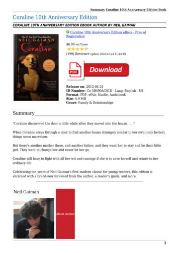
101534-2 SPH E R ICAL M I R RORSSpherical MirrorsWe turn now from images produced by plane mirrors to images produced by mirrors with curved surfaces. In particular, we consider spherical mirrors, which aresimply mirrors in the shape of a small section of the surface of a sphere. A planemirror is in fact a spherical mirror with an infinitely large radius of curvature andthus an approximately flat surface.Making a Spherical MirrorWe start with the plane mirror of Fig. 34-8a, which faces leftward toward anobject O that is shown and an observer that is not shown. We make a concavemirror by curving the mirror’s surface so it is concave (“caved in”) as inFig. 34-8b. Curving the surface in this way changes several characteristics of themirror and the image it produces of the object:OI1. The center of curvature C (the center of the sphere of which the mirror’s surface is part) was infinitely far from the plane mirror; it is now closer but still infront of the concave mirror.2. The field of view — the extent of the scene that is reflected to the observer —was wide; it is now smaller.3. The image of the object was as far behind the plane mirror as the object was infront; the image is farther behind the concave mirror; that is, i is greater.4. The height of the image was equal to the height of the object; the height of theimage is now greater. This feature is why many makeup mirrors and shavingmirrors are concave — they produce a larger image of a face.We can make a convex mirror by curving a plane mirror so its surface isconvex (“flexed out”) as in Fig. 34-8c. Curving the surface in this way (1) movesthe center of curvature C to behind the mirror and (2) increases the field of view.It also (3) moves the image of the object closer to the mirror and (4) shrinks it.Store surveillance mirrors are usually convex to take advantage of the increase inthe field of view — more of the store can then be seen with a single mirror.pBending the mirrorthis way shiftsthe image away.IOCCentral axisFocal Points of Spherical MirrorsFor a plane mirror, the magnitude of the image distance i is always equal tothe object distance p. Before we can determine how these two distances arerelated for a spherical mirror, we must consider the reflection of light from anobject O located an effectively infinite distance in front of a spherical mirror,on the mirror’s central axis. That axis extends through the center of curvature Cand the center c of the mirror. Because of the great distance between the objectand the mirror, the light waves spreading from the object are plane waves whenthey reach the mirror along the central axis. This means that the rays representingthe light waves are all parallel to the central axis when they reach the mirror.Forming a Focus. When these parallel rays reach a concave mirror like thatof Fig. 34-9a, those near the central axis are reflected through a common point F;two of these reflected rays are shown in the figure. If we placed a (small) card atF, a point image of the infinitely distant object O would appear on the card. (Thiswould occur for any infinitely distant object.) Point F is called the focal point (orfocus) of the mirror, and its distance from the center of the mirror c is the focallength f of the mirror.If we now substitute a convex mirror for the concave mirror, we find that theparallel rays are no longer reflected through a common point. Instead, theydiverge as shown in Fig. 34-9b. However, if your eye intercepts some of thereflected light, you perceive the light as originating from a point source behindthe mirror. This perceived source is located where extensions of the reflected rayspass through a common point (F in Fig. 34-9b). That point is the focal point (ori(a)cpri(b)Bending it thisway shifts theimage closer.OIcpiCentral axisCr(c)Figure 34-8 (a) An object O forms a virtualimage I in a plane mirror. (b) If the mirroris bent so that it becomes concave, theimage moves farther away and becomeslarger. (c) If the plane mirror is bent sothat it becomes convex, the image movescloser and becomes smaller.
1016CHAPTE R 34 I MAG ESTo find the focus,send in rays parallelto the central axis.CIf you intercept thereflections, they seemto come from this axisfrf(a)r(b)Figure 34-9 (a) In a concave mirror, incident parallel light rays are brought to a realfocus at F, on the same side of the mirror as the incident light rays. (b) In a convex mirror, incident parallel light rays seem to diverge from a virtual focus at F, on the side ofthe mirror opposite the light rays.focus) F of the convex mirror, and its distance from the mirror surface is the focallength f of the mirror. If we placed a card at this focal point, an image of object Owould not appear on the card; so this focal point is not like that of a concavemirror.Two Types. To distinguish the actual focal point of a concave mirror fromthe perceived focal point of a convex mirror, the former is said to be a real focalpoint and the latter is said to be a virtual focal point. Moreover, the focal length fof a concave mirror is taken to be a positive quantity, and that of a convex mirrora negative quantity. For mirrors of both types, the focal length f is related to theradius of curvature r of the mirror byf ! 12 r(34-3)(spherical mirror),where r is positive for a concave mirror and negative for a convex mirror.Images from Spherical MirrorsInside. With the focal point of a spherical mirror defined, we can find the relation between image distance i and object distance p for concave and convexspherical mirrors. We begin by placing the object O inside the focal point of theconcave mirror — that is, between the mirror and its focal point F (Fig. 34-10a).Changing the locationof the object relative toF changes the image.OVirtualimage IOOI(i – )FFI(i )(a)fpiParallel raysp f(b)FRealimage IiFigure 34-10 (a) An object O inside the focal point of a concave mirror, and its virtual image I. (b) The object at thefocal point F. (c) The object outside the focal point, and its real image I.p(c)f
34-2 SPH E R ICAL M I R RORSAn observer can then see a virtual image of O in the mirror: The image appearsto be behind the mirror, and it has the same orientation as the object.If we now move the object away from the mirror until it is at the focal point,the image moves farther and farther back from the mirror until, when the objectis at the focal point, the image is at infinity (Fig. 34-10b). The image is then ambiguous and imperceptible because neither the rays reflected by the mirror northe ray extensions behind the mirror cross to form an image of O.Outside. If we next move the object outside the focal point — that is, fartheraway from the mirror than the focal point — the rays reflected by the mirror converge to form an inverted image of object O (Fig. 34-10c) in front of the mirror.That image moves in from infinity as we move the object farther outside F. If youwere to hold a card at the position of the image, the image would show up on thecard — the image is said to be focused on the card by the mirror. (The verb “focus,”which in this context means to produce an image, differs from the noun “focus,”which is another name for the focal point.) Because this image can actually appearon a surface, it is a real image — the rays actually intersect to create the image, regardless of whether an observer is present. The image distance i of a real image is apositive quantity, in contrast to that for a virtual image.We can now generalize aboutthe location of images from spherical mirrors:Real images form on the side of a mirror where the object is, and virtual imagesform on the opposite side.Main Equation. As we shall prove in Module 34-6, when light rays from an object make only small angles with the central axis of a spherical mirror, a simple equation relates the object distance p, the image distance i, and the focal length f :111 !pif(spherical mirror).(34-4)We assume such small angles in figures such as Fig. 34-10, but for clarity therays are drawn with exaggerated angles. With that assumption, Eq. 34-4 appliesto any concave, convex, or plane mirror. For a convex or plane mirror, only avirtual image can be formed, regardless of the object’s location on the centralaxis. As shown in the example of a convex mirror in Fig. 34-8c, the image is always on the opposite side of the mirror from the object and has the same orientation as the object.Magnification. The size of an object or image, as measured perpendicular tothe mirror’s central axis, is called the object or image height. Let h represent theheight of the object, and h# the height of the image. Then the ratio h#/h is calledthe lateral magnification m produced by the mirror. However, by convention, thelateral magnification always includes a plus sign when the image orientation isthat of the object and a minus sign when the image orientation is opposite that ofthe object. For this reason, we write the formula for m as m !h#h(lateral magnification).(34-5)We shall soon prove that the lateral magnification can also be written asm!"ip(lateral magnification).(34-6)For a plane mirror, for which i ! "p, we have m ! 1. The magnificationof 1 means that the image is the same size as the object. The plus sign means that1017
1018CHAPTE R 34 I MAG ESTable 34-1 Your Organizing Table for ignTypeOrientationof fof rof iof mAnywhereInside FConcaveOutside FConvexAnywherethe image and the object have the same orientation. For the concave mirror ofFig. 34-10c, m " "1.5.Organizing Table. Equations 34-3 through 34-6 hold for all plane mirrors,concave spherical mirrors, and convex spherical mirrors. In addition to thoseequations, you have been asked to absorb a lot of information about thesemirrors, and you should organize it for yourself by filling in Table 34-1. UnderImage Location, note whether the image is on the same side of the mirror asthe object or on the opposite side. Under Image Type, note whether the imageis real or virtual. Under Image Orientation, note whether the image has thesame orientation as the object or is inverted. Under Sign, give the sign of thequantity or fill in % if the sign is ambiguous. You will need this organization totackle homework or a test.Figure 34-11 (a, b) Four rays that may bedrawn to find the image formed by a concave mirror. For the object positionshown, the image is real, inverted, andsmaller than the object. (c, d) Four similarrays for the case of a convex mirror. For aconvex mirror, the image is always virtual,oriented like the object, and smaller thanthe object. [In (c), ray 2 is initially directedtoward focal point F. In (d), ray 3 is initially directed toward center of curvature C.]Locating Images by Drawing RaysFigures 34-11a and b show an object O in front of a concave mirror. We cangraphically locate the image of any off-axis point of the object by drawing a raydiagram with any two of four special rays through the point:Any two of these four rayswill locate the image.bCOFOcI2Cade4cFI31(b)(a)132OIcFCO(c)Here too, any two rays4will locate the image.CIcF(d)
34-2 SPH E R ICAL M I R RORS10191. A ray that is initially parallel to the central axis reflects through the focal pointF (ray 1 in Fig. 34-11a).2. A ray that reflects from the mirror after passing through the focal pointemerges parallel to the central axis (ray 2 in Fig. 34-11a).3. A ray that reflects from the mirror after passing through the center of curvature C returns along itself (ray 3 in Fig. 34-11b).4. A ray that reflects from the mirror at point c is reflected symmetrically aboutthat axis (ray 4 in Fig. 34-11b).The image of the point is at the intersection of the two special rays you choose.The image of the object can then be found by locating the images of two or moreof its off-axis points (say, the point most off axis) and then sketching in the rest ofthe image. You need to modify the descriptions of the rays slightly to apply themto convex mirrors, as in Figs. 34-11c and d.Proof of Equation 34-6We are now in a position to derive Eq. 34-6 (m ! "i/p), the equation for the lateral magnification of an object reflected in a mirror. Consider ray 4 in Fig. 34-11b.It is reflected at point c so that the incident and reflected rays make equal angleswith the axis of the mirror at that point.The two right triangles abc and dec in the figure are similar (have the sameset of angles); so we can writecdde!.abcaThe quantity on the left (apart from the question of sign) is the lateral magnificationm produced by the mirror. Because we indicate an inverted image as a negative magnification, we symbolize this as "m. However, cd ! i and ca ! p;
What Is Physics? One goal of physics is to discover the basic laws governing light, such as the law of refraction. A broader goal is to put those laws to use, and perhaps the most important use is the production of images.The first photographic images,made in 1824, were only novelt