Transcription
Mechanical Engineering Principles
This Page Intentionally Left Blank
Mechanical Engineering PrinciplesJOHN BIRDCARL ROSSBSc, CEng, CMath, FIMA, MIEE, FCollP, FIIEBSc, PhD, DSc, CEng, FRINA, MSNAMENewnesOXFORDAUCKLAND BOSTONJOHANNESBURGMELBOURNE NEW DELHI
NewnesAn imprint of Butterworth-HeinemannLinacre House, Jordan Hill, Oxford OX2 8DP225 Wildwood Avenue, Woburn, MA 01801-2041A division of Reed Educational and Professional Publishing LtdFirst published 2002 John Bird and Carl Ross 2002All rights reserved. No part of this publicationmay be reproduced in any material form (includingphotocopying or storing in any medium by electronicmeans and whether or not transiently or incidentallyto some other use of this publication) without thewritten permission of the copyright holder exceptin accordance with the provisions of the Copyright,Designs and Patents Act 1988 or under the terms of alicence issued by the Copyright Licensing Agency Ltd,90 Tottenham Court Road, London, England W1P 9HE.Applications for the copyright holder’s written permissionto reproduce any part of this publication should be addressedto the publishersBritish Library Cataloguing in Publication DataA catalogue record for this book is available from the British LibraryLibrary of Congress Cataloguing in Publication DataA catalogue record for this book is available from the Library of CongressISBN 0 7506 5228 4For information on all Newnes publications visit our website at www.newnespress.comTypeset by Laserwords Pvt. Ltd., Chennai, IndiaPrinted and bound in
ContentsPrefaceixPart 1 Statics and strength of materials11 The effects of forces on materials1.1 Introduction1.2 Tensile force1.3 Compressive force1.4 Shear force1.5 Stress1.6 Strain1.7 Elasticity, limit ofproportionality and elastic limit1.8 Hooke’s law1.9 Ductility, brittlenessand malleability1.10 Modulus of rigidity1.11 Thermal strain1.12 Compound bars112222367111212132 Tensile testing2.1 The tensile test2.2 Worked problemson tensile testing2.3 Further worked problemson tensile testing18183 cting at a pointScalar and vector quantitiesCentre of gravity and equilibriumForcesThe resultant oftwo coplanar forcesTriangle of forces methodThe parallelogramof forces methodResultant of coplanarforces by calculationResultant of more thantwo coplanar forcesCoplanar forces in equilibriumResolution of forcesSummary4 Forces in structures4.1 Introduction1921272829293032343740404.2 Worked problems on mechanismsand pin-jointed trusses4.3 Graphical method4.4 Method of joints (amathematical method)4.5 The method of sections(a mathematical method)Assignment 141424652555 Simply supported beams5.1 The moment of a force5.2 Equilibrium and theprinciple of moments5.3 Simply supported beamshaving point loads5.4 Simply supportedbeams with couples57576 Bending moment andshear force diagrams6.1 Introduction6.2 Bending moment (M)6.3 Shearing force (F)6.4 Worked problems onbending moment andshearing force diagrams6.5 Uniformly distributed loads697 First and second moment of areas7.1 Centroids7.2 The first moment of area7.3 Centroid of area betweena curve and the x-axis7.4 Centroid of area betweena curve and the y-axis7.5 Worked problems oncentroids of simple shapes7.6 Further worked problems oncentroids of simple shapes7.7 Second moments ofarea of regular sections7.8 Second moment of areafor ‘built-up’ sectionsAssignment 25861646969697078848484848586878896102
viMECHANICAL ENGINEERING PRINCIPLES8 Bending of beams8.1 IntroductionMEσ yIR8.3 Worked problems onthe bending of beams8.2 To prove that9 Torque9.1 Couple and torque9.2 Work done and powertransmitted by a constant torque9.3 Kinetic energy andmoment of inertia9.4 Power transmission and efficiency10 Twisting of shafts10.1 122Assignment 3126120Part 2 Dynamics12711 Linear11.111.211.311.411.5127127127129130132and angular motionThe radianLinear and angular velocityLinear and angular accelerationFurther equations of motionRelative velocity12 Linear momentum and impulse12.1 Linear momentum12.2 Impulse and impulsive forces13613613913 Force,13.113.213.313.4144144144147mass and accelerationIntroductionNewton’s laws of motionCentripetal accelerationRotation of a rigidbody about a fixed axis13.5 Moment of inertia (I )14 Work,14.114.214.314.414.517017017017217316 Motion in a circle16.1 Introduction16.2 Motion on a curved banked track16.3 Conical pendulum16.4 Motion in a vertical circle16.5 Centrifugal clutch18218218418518718917 6173174175177116τTGθ rJLWorked problems onthe twisting of shaftsTo prove that15 Friction15.1 Introduction to friction15.2 Coefficient of friction15.3 Applications of friction15.4 Friction on an inclined plane15.5 Motion up a plane withthe pulling force Pparallel to the plane15.6 Motion down a planewith the pulling forceP parallel to the plane15.7 Motion up a plane dueto a horizontal force P15.8 The efficiency of a screw jack149149energy and powerWorkEnergyPowerPotential and kinetic energyKinetic energy of rotation153153157159162165Assignment 4169harmonic motionIntroductionSimple harmonic motion (SHM)The spring-mass systemThe simple pendulumThe compound pendulumTorsional vibrations18 Simple machines18.1 Machines18.2 Force ratio, movementratio and efficiency18.3 Pulleys18.4 The screw-jack18.5 Gear trains18.6 LeversAssignment 5198198198200202203205209Part 3 Heat transfer and fluid mechanics21119 Heat19.119.219.319.419.5211211212212214energy and transferIntroductionThe measurement of temperatureSpecific heat capacityChange of stateLatent heats of fusionand vaporisation19.6 A simple refrigerator19.7 Conduction, convection and radiation19.8 Vacuum flask215217217218
CONTENTS19.9Use of insulationin conserving fuel20 Thermal expansion20.1 Introduction20.2 Practical applicationsof thermal expansion20.3 Expansion and contraction of water20.4 Coefficient of linear expansion20.5 Coefficient of superficial expansion20.6 Coefficient of cubic expansionAssignment 621822122122122222222422522921 Hydrostatics21.1 Pressure21.2 Fluid pressure21.3 Atmospheric pressure21.4 Archimedes’ principle21.5 Measurement of pressure21.6 Barometers21.7 Absolute and gauge pressure21.8 The manometer21.9 The Bourdon pressure gauge21.10 Vacuum gauges21.11 Hydrostatic pressureon submerged surfaces21.12 Hydrostatic thruston curved surfaces21.13 Buoyancy21.14 The stability of floating bodies23023023123223323523523723723823922 247248249249250250250flowIntroductionDifferential pressure flowmetersOrifice plateVenturi tubeFlow nozzlePitot-static tubeMechanical flowmetersDeflecting vane flowmeterTurbine type .16Float and tapered-tube meterElectromagnetic flowmeterHot-wire anemometerChoice of flowmeterEquation of continuityBernoulli’s EquationImpact of a jet ona stationary plate23 Ideal gas laws23.1 Introduction23.2 Boyle’s law23.3 Charles’ law23.4 The pressure law23.5 Dalton’s law of partial pressure23.6 Characteristic gas equation23.7 Worked problems on thecharacteristic gas equation23.8 Further worked problems onthe characteristic gas equation24 The measurement of temperature24.1 Introduction24.2 Liquid-in-glass thermometer24.3 Thermocouples24.4 Resistance thermometers24.5 Thermistors24.6 Pyrometers24.7 Temperature indicatingpaints and crayons24.8 Bimetallic thermometers24.9 Mercury-in-steel thermometer24.10 Gas thermometers24.11 Choice of measuring deviceAssignment 63267267267268270272272274274274275275277A list of formulae279Greek alphabet283Answers to multiple-choice questions284Index287
Preface(i) National Certificate/Diploma courses inMechanical Engineering(ii) Mechanical Engineering Principles (Advanced GNVQ Unit 8)(iii) Further Mechanical Engineering Principles(Advanced GNVQ Unit 12)(iv) Any introductory/access/foundation courseinvolving Mechanical Engineering Principlesat University, and Colleges of Further andHigher education.Mathematics and Science, each topic considered inthe text is presented in a way that assumes thatthe reader has little previous knowledge of thattopic.Mechanical Engineering Principles contains over280 worked problems, followed by over 470 further problems (all with answers). The furtherproblems are contained within some 130 Exercises;each Exercise follows on directly from the relevant section of work, every few pages. In addition,the text contains 260 multiple-choice questions (allwith answers), and 260 short answer questions,the answers for which can be determined from thepreceding material in that particular chapter. Whereat all possible, the problems mirror practical situations found in mechanical engineering. 330 linediagrams enhance the understanding of the theory.At regular intervals throughout the text are some7 Assignments to check understanding. For example, Assignment 1 covers material contained inChapters 1 to 4, Assignment 2 covers the materialin Chapters 5 to 7, and so on. No answers are givenfor the questions in the assignments, but a lecturer’sguide has been produced giving full solutions andsuggested marking scheme. The guide is offered freeto those staff that adopt the text for their course.At the end of the text, a list of relevant formulaeis included for easy reference.‘Learning by Example’ is at the heart ofMechanical Engineering Principles.Although pre-requisites for the modules coveredin this book include GCSE/GNVQ intermediate inJohn Bird and Carl RossUniversity of PortsmouthMechanical Engineering Principles aims tobroaden the reader’s knowledge of the basicprinciples that are fundamental to mechanicalengineering design and the operation of mechanicalsystems.Modern engineering systems and products stillrely upon static and dynamic principles to makethem work. Even systems that appear to be entirelyelectronic have a physical presence governed by theprinciples of statics.For clarity, the text is divided into three sections,these being:Part 1 Statics and strength of materialsPart 2 DynamicsPart 3 Heat transfer and fluid mechanicsMechanical Engineering Principles covers thefollowing syllabuses:
Statics and strength ofmaterialsPart 11The effects of forces on materials perform calculations using Hooke’s lawAt the end of this chapter you should beable to: plot a load/extension graph from givendata define force and state its unit define ductility, brittleness and malleability, with examples of each recognise a tensile force and state relevantpractical examples recognise a compressive force and staterelevant practical examples define rigidity or shear modulus understand thermal stresses and strains calculates stresses in compound bars recognise a shear force and state relevantpractical examples define stress and state its unitF calculate stress σ from σ A define strainx calculate strain ε from ε L define elasticity, plasticity, limit of proportionality and elastic limit state Hooke’s law define Young’s modulus of elasticity Eand stiffness appreciate typical values for Eσ calculate E from E ε1.1 IntroductionA force exerted on a body can cause a change ineither the shape or the motion of the body. The unitof force is the newton, N.No solid body is perfectly rigid and when forcesare applied to it, changes in dimensions occur. Suchchanges are not always perceptible to the humaneye since they are so small. For example, the spanof a bridge will sag under the weight of a vehicleand a spanner will bend slightly when tighteninga nut. It is important for engineers and designers toappreciate the effects of forces on materials, togetherwith their mechanical properties.The three main types of mechanical force that canact on a body are: (i) tensile, (ii) compressive, and(iii) shear
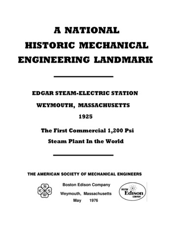
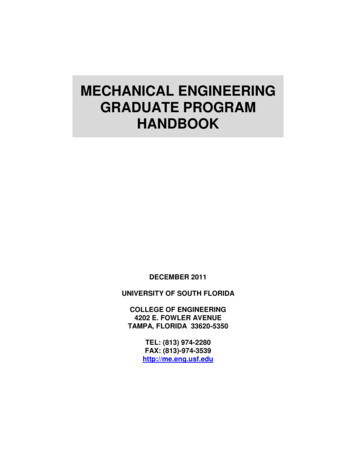
2MECHANICAL ENGINEERING PRINCIPLESRivet1.2 Tensile forceForceTension is a force that tends to stretch a material,as shown in Figure 1.1. For example,(i) the rope or cable of a crane carrying a load isin tension(ii)rubber bands, when stretched, are in tensionForceFigure 1.3(ii)a guillotine cutting sheet metal, or gardenshears, each provide a shear force(iii)a horizontal beam is subject to shear force(iv)transmission joints on cars are subject to shearforcesForceA shear force can cause a material to bend, slide ortwist.Figure 1.1(iii)Forcewhen a nut is tightened, a bolt is under tensionProblem 1. Figure 1.4(a) represents a craneand Figure 1.4(b) a transmission joint. Statethe types of forces acting, labelled A to F .A tensile force, i.e. one producing tension, increasesthe length of the material on which it acts.BC1.3 Compressive forceACompression is a force that tends to squeezeor crush a material, as shown in Figure 1.2. Forexample,DEForceFLoad(b)(a)Figure 1.4ForceForceFigure 1.2(i) a pillar supporting a bridge is in compression(ii)the sole of a shoe is in compression(iii)the jib of a crane is in compressionA compressive force, i.e. one producing compression, will decrease the length of the material onwhich it acts.1.4 Shear forceShear is a force that tends to slide one face of thematerial over an adjacent face. For example,(i) a rivet holding two plates together is inshear if a tensile force is applied between theplates — as shown in Figure 1.3(a) For the crane, A, a supporting member, isin compression, B, a horizontal beam, is inshear, and C, a rope, is in tension.(b)For the transmission joint, parts D and F arein tension, and E, the rivet or bolt, is inshear.1.5 StressForces acting on a material cause a change in dimensions and the material is said to be in a state ofstress. Stress is the ratio of the applied force F tocross-sectional area A of the material. The symbolused for tensile and compressive stress is σ (Greekletter sigma). The unit of stress is the Pascal, Pa,where 1 Pa 1 N/m2 . Henceσ FPaA
THE EFFECTS OF FORCES ON MATERIALSwhere F is the force in Newton’s and A is thecross-sectional area in square metres. For tensileand compressive forces, the cross-sectional area isthat which is at right angles to the direction of theforce. For a shear force the shear stress is equalto F /A, where the cross-sectional area A is thatwhich is parallel to the direction of the force. Thesymbol used for shear stress is the Greek lettertau, τ .Problem 2. A rectangular bar having across-sectional area of 75 mm2 has a tensileforce of 15 kN applied to it. Determine thestress in the bar.Now try the following exerciseExercise 1A rectangular bar having a cross-sectionalarea of 80 mm2 has a tensile force of20 kN applied to it. Determine the stressin the bar.[250 MPa]2.A circular cable has a tensile force of1 kN applied to it and the force producesa stress of 7.8 MPa in the cable. Calculatethe diameter of the cable.[12.78 mm]3.A square-sectioned support of side 12 mmis loaded with a compressive force of10 kN. Determine the compressive stressin the support.[69.44 MPa]4.A bolt having a diameter of 5 mm isloaded so that the shear stress in it is120 MPa. Determine the value of theshear force on the bolt.[2.356 kN]5.A split pin requires a force of 400 N toshear it. The maximum shear stress beforeshear occurs is 120 MPa. Determine theminimum diameter of the pin.[2.06 mm]6.A tube of outside diameter 60 mm andinside diameter 40 mm is subjected to aload of 60 kN. Determine the stress in thetube.[38.2 MPa]F15 103 NStress in bar, σ A75 10 6 m2Problem 3. A circular wire has a tensileforce of 60.0 N applied to it and this forceproduces a stress of 3.06 MPa in the wire.Determine the diameter of the wire.Force F 60.0 N andstress σ 3.06 MPa 3.06 106 PaSinceσ FAthen area,A 60.0 NF σ3.06 106 Pa1.6 Strain 19.61 10 6 m2 19.61 mm22Cross-sectional area A πd4 ;hence 19.61 πd 2, from which,44 19.61from which, d d2 πi.e. diameter of wire 5.0 mmFurther problems on stress1.Cross-sectional area A 75 mm2 75 10 6 m2and force F 15 kN 15 103 N 0.2 109 Pa 200 MPa3The fractional change in a dimension of a materialproduced by a force is called the strain. For a tensileor compressive force, strain is the ratio of the changeof length to the original length. The symbol used forstrain is ε (Greek epsilon). For a material of lengthL metres which changes in length by an amount xmetres when subjected to stress,ε 4 19.61π xLStrain is dimension-less and is often expressed as apercentage, i.e.percentage strain x 100L
4MECHANICAL ENGINEERING PRINCIPLESdetermine the minimum breadth of the barwhen loaded with a force of 3 kN.(b) If the bar in (a) is 2 m long anddecreases in length by 0.25 mm when theforce is applied, determine the strain and thepercentage strain.xAppliedforceγLReactionforce(a)Figure 1.5For a shear force, strain is denoted by the symbol γ (Greek letter gamma) and, with reference toFigure 1.5, is given by: 150 10 6 m2 150 mm2xγ LProblem 4. A bar 1.60 m long contractsaxially by 0.1 mm when a compressive loadis applied to it. Determine the strain and thepercentage strain.0.1 mmcontraction original length1.60 103 mm0.1 0.00006251600Strain ε Percentage strain 0.0000625 100 0.00625%Problem 5. A wire of length 2.50 m has apercentage strain of 0.012% when loadedwith a tensile force. Determine the extensionof the wire.force Farea AF3000 Nthen, area, A σ20 106 PaSince stress, σ Cross-sectional area width breadth, hence150area 15 mmwidth10contractionε original lengthbreadth (b)Strain,0.25 0.0001252000Percentage strain 0.000125 100 0.0125%Problem 7. A pipe has an outside diameterof 25 mm, an inside diameter of 15 mm andlength 0.40 m and it supports a compressiveload of 40 kN. The pipe shortens by 0.5 mmwhen the load is applied. Determine (a) thecompressive stress, (b) the compressivestrain in the pipe when supporting this load.Original length of wire 2.50 m 2500 mm0.012 0.00012100extension xStrain ε original length Land strain hence, extension x εL (0.00012)(2500) 0.30 mmProblem 6. (a) A rectangular metal bar hasa width of 10 mm and can support amaximum compressive stress of 20 MPa;Compressive force F 40 kN 40000 N,and cross-sectional area A π 2(D d 2 ),4where D outside diameter 25 mm andd inside diameter 15 mm. Henceπ(252 152 ) mm24π (252 152 ) 10 6 m24A 3.142 10 4 m2
THE EFFECTS OF FORCES ON MATERIALS(a) Compressive stress, 40000 NF σ A3.142 10 4 m20.001963 m2 80.03 MPa,which is the compressive stress in the punch.Contraction of pipe when loaded,x 0.5 mm 0.0005 m, and original lengthL 0.40 m. Hence, compressive strain,ε 157.1 103 N 8.003 107 Pa 12.73 107 Pa 127.3 MPa(b)5Problem 9. A rectangular block of plasticmaterial 500 mm long by 20 mm wide by300 mm high has its lower face glued to abench and a force of 200 N is applied to theupper face and in line with it. The upper facemoves 15 mm relative to the lower face.Determine (a) the shear stress, and (b) theshear strain in the upper face, assuming thedeformation is uniform.0.0005x L0.4 0.00125 (or 0.125%)Problem 8. A circular hole of diameter50 mm is to be punched out of a 2 mm thickmetal plate. The shear stress needed to causefracture is 500 MPa. Determine (a) theminimum force to be applied to the punch,and (b) the compressive stress in the punchat this value.(a)forcearea parallel to the forceShear stress, τ Area of any face parallel to the force 500 mm 20 mm(a) The area of metal to be sheared, A perimeterof hole thickness of plate. (0.5 0.02) m2 0.01 m2Hence, shear stress,Perimeter of hole πd π(50 10 3 )τ 0.1571 m.200 N0.01 m2 20000 Pa or 20 kPa 3Hence, shear area, A 0.1571 2 10 3.142 10 4 m2(b)x(see side viewLin Figure 1.6)15 0.05 (or 5%) 300Shear strain, γ force,areashear force shear stress areaSince shear stress (500 106 3.142 10 4 ) N 157.1 kN,which is the minimum force to be applied tothe punch.(b)π(0.050)2πd 2 Area of punch 44 0.001963 m2forceCompressive stress area500 mmx 15 mmAppliedforceγL 300 mmReactionforceFigure 1.6
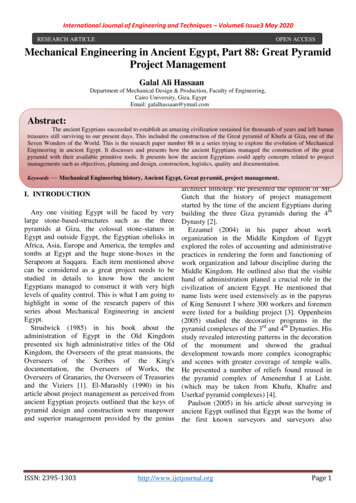
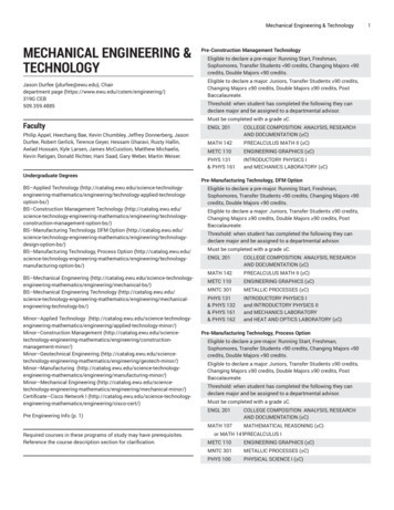
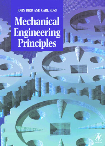
MECHANICAL ENGINEERING PRINCIPLES1.7 Elasticity, limit of proportionalityand elastic limitNow try the following exerciseExercise 2 Further problems on strain1. A wire of length 4.5 m has a percentagestrain of 0.050% when loaded with a tensile force. Determine the extension in thewire.[2.25 mm]2. A metal bar 2.5 m long extends by0.05 mm when a tensile load is applied toit. Determine (a) the strain, (b) thepercentage strain.[(a) 0.00002(b) 0.002%]3. An 80 cm long bar contracts axiallyby 0.2 mm when a compressive load isapplied to it. Determine the strain and thepercentage strain.[0.00025, 0.025%]4. A pipe has an outside diameter of 20 mm,an inside diameter of 10 mm and length0.30 m and it supports a compressiveload of 50 kN. The pipe shortens by0.6 mm when the load is applied.Determine (a) the compressive stress,(b) the compressive strain in the pipewhen supporting this load.[(a) 212.2 MPa(b) 0.002 or 0.20%]5. When a circular hole of diameter 40 mmis punched out of a 1.5 mm thick metalplate, the shear stress needed to causefracture is 100 MPa. Determine (a) theminimum force to be applied to thepunch, and (b) the compressive stress inthe punch at this value.[(a) 18.85 kN(b) 15.0 MPa]6. A rectangular block of plastic material400 mm long by 15 mm wide by 300 mmhigh has its lower face fixed to a benchand a force of 150 N is applied to theupper face and in line with it. The upperface moves 12 mm relative to the lowerface. Determine (a) the shear stress, and(b) the shear strain in the upper face,assuming the deformation is uniform.[(a) 25 kPaElasticity is the ability of a material to return to itsoriginal shape and size on the removal of externalforces.Plasticity is the property of a material of beingpermanently deformed by a force without breaking.Thus if a material does not return to the originalshape, it is said to be plastic.Within certain load limits, mild steel, copper,polythene and rubber are examples of elastic materials; lead and plasticine are examples of plasticmaterials.If a tensile force applied to a uniform bar of mildsteel is gradually increased and the correspondingextension of the bar is measured, then provided theapplied force is not too large, a graph depicting theseresults is likely to be as shown in Figure 1.7. Sincethe graph is a straight line, extension is directlyproportional to the applied force.Force F6(b) 0.04% or 4%]Extension xFigure 1.7The point on the graph where extension is nolonger proportional to the applied force is known asthe limit of proportionality. Just beyond this pointthe material can behave in a non-linear elastic manner, until the elastic limit is reached. If the appliedforce is large, it is found that the material becomesplastic and no longer returns to its original lengthwhen the force is removed. The material is thensaid to have passed its elastic limit and the resulting graph of force/extension is no longer a straightline. Stress, σ F /A, from Section 1.5, and since,for a particular bar, area A can be considered as aconstant, then F σ .Strain ε x/L, from Section 1.6, and since fora particular bar L is constant, then x ε. Hencefor stress applied to a material below the limit of
THE EFFECTS OF FORCES ON MATERIALSproportionality a graph of stress/strain will be asshown in Figure 1.8, and is a similar shape to theforce/extension graph of Figure 1.7.7titanium alloy 110 GPa, diamond 1200 GPa, mildsteel 210 GPa, lead 18 GPa, tungsten 410 GPa, castiron 110 GPa, zinc 85 GPa, glass fibre 72 GPa,carbon fibre 300 GPa.StiffnessStress σA material having a large value of Young’s modulusis said to have a high value of material stiffness,where stiffness is defined as:Stiffness Strain εforce Fextension xFor example, mild steel is a much stiffer materialthan lead.Figure 1.8σFx,σ and ε ,εALF FLFL then E AxAxxALSince E 1.8 Hooke’s lawHooke’s law states:Within the limit of proportionality, the extension of amaterial is proportional to the applied forceIt follows, from Section 1.7, that:Within the limit of proportionality of a material, thestrain produced is directly proportional to the stressproducing itYoung’s modulus of elasticityWithin the limit of proportionality, stress α strain,hencestress (a constant) strainThis constant of proportionality is called Young’smodulus of elasticity and is given the symbol E.The value of E may be determined from the gradientof the straight line portion of the stress/strain graph.The dimensions of E are pascals (the same as forstress, since strain is dimension-less).E σPaεSome typical values for Young’s modulus ofelasticity, E, include: Aluminium alloy 70 GPa(i.e. 70 109 Pa), brass 90 GPa, copper 96 GPa,i.e.E (stiffness) LA F is also the gradient of thexforce/extension graph, henceStiffnessE (gradient of force/extension graph) LASince L and A for a particular specimen are constant, the greater Young’s modulus the greater thematerial stiffness.Problem 10. A wire is stretched 2 mm by aforce of 250 N. Determine the force thatwould stretch the wire 5 mm, assuming thatthe limit of proportionality is not exceeded.Hooke’s law states that extension x is proportionalto force F , provided that the limit of proportionalityis not exceeded, i.e. x F or x kF where k is aconstant.
8MECHANICAL ENGINEERING PRINCIPLESWhen x 2 mm, F 250 N, thus 2 k(250),12 from which, constant k 250125When x 5 mm, then 5 kF 1i.e.5 F125from which, forceThus to stretch the wire 5 mm a force of 625 Nis required.Problem 11. A force of 10 kN applied to acomponent produces an extension of0.1 mm. Determine (a) the force needed toproduce an extension of 0.12 mm, and(b) the extension when the applied force is6 kN, assuming in each case that the limit ofproportionality is not exceeded.From Hooke’s law, extension x is proportional toforce F within the limit of proportionality, i.e.x F or x kF , where k is a constant. If a forceof 10 kN produces an extension of 0.1 mm, then0.1 0.010.1 k(10), from which, constant k 10(a) When an extension x 0.12 mm, then0.12 k(F ), i.e. 0.12 0.01F , from which,(b)5000 NF A0.000314 m2 15.92 106 Pa 15.92 MPa(b)Since E σthenε15.92 106 Paσ 0.000166E96 109 PaxStrain ε , hence extension,Lx εL (0.000166)(2.0) 0.000332 mstrain ε F 5(125) 625 Nforce F Stress, σ 0.12 12 kN0.01When force F 6 kN, thenextension x k(6) (0.01)(6) 0.06 mmProblem 12. A copper rod of diameter20 mm and length 2.0 m has a tensile forceof 5 kN applied to it. Determine (a) thestress in the rod, (b) by how much the rodextends when the load is applied. Take themodulus of elasticity for copper as 96 GPa.i.e. extension of rod is 0.332 mm.Problem 13. A bar of thickness 15 mm andhaving a rectangular cross-section carries aload of 120 kN. Determine the minimumwidth of the bar to limit the maximum stressto 200 MPa. The bar, which is 1.0 m long,extends by 2.5 mm when carrying a load of120 kN. Determine the modulus of elasticityof the material of the bar.Force, F 120 kN 120000 N and crosssectional area A (15x)10 6 m2 , where x is thewidth of the rectangular bar in millimetresF, from which,A120000 NF 6 10 4 m2A σ200 106 PaStress σ 6 102 mm2 600 mm2Hence 600 15x, from which,width of bar, x 600 40 mm15and extension of bar 2.5 mm 0.0025 mStrain ε x0.0025 0.0025L1.0(a) Force F 5 kN 5000 N andcross-sectional area A πd4Modulus of elasticity, E 2200 106stress strain0.0025 80 109 80 GPa2 π (0.020)4 0.000314 m2Problem 14. An aluminium alloy rod has alength of 200 mm and a diameter of 10 mm.
THE EFFECTS OF FORCES ON MATERIALSWhen subjected to a compressive force thelength of the rod is 199.6 mm. Determine(a) the stress in the rod when loaded, and(b) the magnitude of the force.Take the modulus of elasticity for aluminiumalloy as 70 GPa.(a) Original length of rod, L 200 mm, finallength of rod 199.6 mm, hence contraction,x 0.4 mm. Thus, strain,x0.4 0.002L200stress σModulus of elasticity, E , hencestrain εSince the modulus of elasticity,E stress σ,strain εthen strain, ε 0.7859 106 Paσ E90 109 Pa 8.732 10 6 .Strain,ε ε stress, σ Eε 70 10 0.0029contraction xoriginal length Lthus, contraction, x εL 8.732 10 6 0.500 4.37 10 6 m.9 140 106 Pa 140 MPa(b)Since stress σ force F, then force, F σ Aarea ACross-sectional area, A π(0.010)2πd 2 44 7.854 10 5 m2 .Hence, compressive force,F σ A 140 106 7.854 10 5 11.0 kNProblem 15. A brass tube has an internaldiameter of 120 mm and an outside diameterof 150 mm and is used to support a load of5 kN. The tube is 500 mm long before theload is applied. Determine by how much thetube contracts when loaded, taking themodulus of elasticity for brass as 90 GPa.Force in tube, F 5 kN 5000 N, and crosssectional area of tube,A π 2π(D d 2 ) (0.1502 0.1202 )44 0.006362 m2 .F5000 NStress in tube, σ A0.006362 m2 0.7859 106 Pa.Thus, when loaded, the tube contracts by4.37 μm.Problem 16. In an experiment to determinethe modulus of elasticity of a sample of mildsteel, a wire is loaded and the correspondingextension noted. The results of the experiment are as shown.Load (N)0 40 110 160 200 250 290 340Extension (mm) 0 1.2 3.3 4.8 6.0 7.5 10.0 16.2Draw the load/extension graph.The mean diameter of the wire is 1.3 mmand its length is 8.0 m. Determine themodulus of elasticity E of the sample, andthe stress at the limit of proportionality.A graph of load/extension is shown in Figure 1.9F FLσE A xεxALFis the gradient of the straight line part of thexload/extension graph.Gradient,FBC200 N xAC6 10 3 m 33.33 103 N/mModulus of elasticity (gradient of graph) LA
10MECHANICAL ENGINEERING PRINCIPLESNow try the following exercise360320Exercise 3Load / N280D240200F1.A wire is stretched 1.5 mm by a force of300 N. Determine the force that wouldstretch the wire 4 mm, assuming theelastic limit of the wire is not
Part 3 Heat transfer and fluid mechanics 211 19 Heat energy and transfer 211 19.1 Introduction 211 19.2 The measurement of temperature 212 19.3 Specific heat capacity 212 19.4 Change of state 214 19.5 Latent heats of fusion and vaporisation 215 19.6 A simple refrigerator 217 19.7 Condu