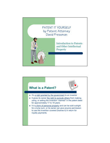
Transcription
PDHonline Course G200 (2 PDH)How to Prepare Patent DrawingsInstructor: Tracy P. Jong, Esq. and ChengNing Jong, PE2012PDH Online PDH Center5272 Meadow Estates DriveFairfax, VA 22030-6658Phone & Fax: 703-988-0088www.PDHonline.orgwww.PDHcenter.comAn Approved Continuing Education Provider
www.PDHcenter.comPDH Course G200www.PDHonline.orgTABLE OF CONTENTSMedia. 2Type of Paper. 5Margins . 5Views . 7Lines . 14Arrangement of Views . 16Scale. 17Symbols . 18Draftsmen Symbols. 19Numbers, letters, and reference characters. 20Copyright or Mask Work Notice . 29Numbering of sheets of drawings . 30Numbering of views. 31Identification of drawings. 33Graphic forms in drawings . 34Design Patents. 34Appendix Extract of Manual of Patent Examining ProcedureSample utility patent (a fun patent to read)Sample design patentExtract of “A Guide to Filing a Design Patent Application” Tracy P. Jong and Cheng–Ning JongPage 1 of 40
www.PDHcenter.comPDH Course G200www.PDHonline.orgMediaThere are two acceptable manners for presenting drawings in utility and design patentapplications: black ink or color. Black and white drawings are normally required. Indiaink, or its equivalent that secures solid black lines, must be used. The patent rulesalso recognize that “on rare occasions, color drawings may be necessary as the onlypractical medium by which to disclose the subject matter.”In those cases where color is required, the color drawings must be of sufficient qualitythat all details in the drawings are reproducible in black and white in the printedpatent. In some circumstances, a petition must be filed with the Patent Office to seekthe filing of color drawings and explaining why color is necessary. On a practical note,the patent websites only have black and white drawings in the patent images. Colordrawings may not produce good images. Color versions are only available from thePTO for a fee and may be inconvenient for people viewing the patent. Of course, youwill not be required to make such petition. That is the responsibility of the patentattorney/agent. However, you should use your expertise to find ways to avoid the useof color whenever possible. This will save time and expense in the patent applicationprocess.All drawings must be made by a process which will give them satisfactoryreproduction characteristics. Every line, number, and letter must be durable, clean,black (except for color drawings), sufficiently dense and dark, and uniformly thick andwell defined. The weight of all lines and letters must be heavy enough to permitadequate reproduction. This requirement applies to all lines (including fine lines),shading, and lines representing cut surfaces in sectional views. Lines and strokes ofdifferent thicknesses may be used in the same drawing where different thicknesseshave a different meaning.The use of shading in views is encouraged if it aids in understanding the invention andif it does not reduce legibility. Shading is used to indicate the surface or shape ofspherical, cylindrical, and conical elements of an object. Flat parts may also be lightlyshaded. Such shading is preferred in the case of parts shown in perspective, but notfor cross sections. Shading will be addressed in greater detail later. Tracy P. Jong and Cheng–Ning JongPage 2 of 40
www.PDHcenter.comPDH Course G200www.PDHonline.orgShading showsdepth and surfacedelineation Tracy P. Jong and Cheng–Ning JongPage 3 of 40
www.PDHcenter.comPDH Course G200www.PDHonline.orgSpaced linesfor shadingSpaced lines for shading are preferred. These lines must be thin, as few in number aspracticable, and they must contrast with the rest of the drawings. As a substitute forshading, heavy lines on the shade side of objects can be used except where theysuperimpose on each other or obscure reference characters.Light should come from the upper left corner at an angle of 45º. Tracy P. Jong and Cheng–Ning JongPage 4 of 40
www.PDHcenter.comPDH Course G200www.PDHonline.orgSurface delineations should preferably be shown by proper shading. Solid blackshading of areas is not permitted, except when used to represent bar graphs or color.Type of PaperThe patent drawing rules require that drawings submitted to the Office must bemade on paper which is flexible, strong, white, smooth, non-shiny, anddurable. All sheets must be reasonably free from cracks, creases, andfolds. Only one side of the sheet may be used for the drawing. Eachsheet must be reasonably free from erasures and must be free fromalterations, overwritings, and interlineations.In practical terms, this means that drawings are on unfolded, unwrinkled standardwhite copy paper (20 lb or 24 lb. varieties work well) or drawing paper. Graph paper isnot preferred. Dot matrix style paper with holes along the edges may not be used.Patent Agent Jack Lo and attorney David Pressman, in How to Make Patent Drawings4th ed. (NOLO 2005), suggest that laser printing paper of 20 or 24 lb. varieties aregood choices. Laser printing is optimal, however, good quality ink jet output may beused. For ink jet output, they suggest not to use laser paper and cheap ink jet paper,explaining that they cause the ink to feather. They prescribe the use of specialty ink jetpapers sold with descriptions such as “matte paper heavyweight,” “archival matte,”and “photoquality ink jet paper” (not glossy! Not shiny!).It is important to note that erasure marks, white-out and corrections are not permitted.These informality defects are often the subject of drawing rejections. A trick of thetrade, if you are doing hand-sketches, is to photocopy the final drawings to rid them ofremnants of corrections.All drawing sheets in an application must be the same size. One of the shorter sidesof the sheet is regarded as its top. The size of the sheets on which drawings are mademust be: 21.0 cm. by 29.7 cm. (DIN size A4), or 21.6 cm. by 27.9 cm. (8 1/2 by 11inches). Size A4 paper is required for PCT (Patent Cooperation Treaty or“international”) applications and foreign applications.MarginsPatent drawings must contain an imaginary margin surrounding the entire page.However, the sheets must not contain rectangular frames around the sight (i.e., theusable surface), but should have scan target points (i.e., cross-hairs) printed on twocater-corner margin corners. The center of the crosshairs should be positioned such Tracy P. Jong and Cheng–Ning JongPage 5 of 40
www.PDHcenter.comPDH Course G200www.PDHonline.orgthat the arms of the crosshairs are in the margin itself. The arms of the crosshairsshould be 2 cm or ¾ inch in length. You may place the cross hairs in the upper leftand lower right corners, or alternatively, in the upper right and lower left corners.Each sheet must include a top margin of at least 2.5 cm. (1 inch), a left side margin ofat least 2.5 cm. (1 inch), a right side margin of at least 1.5 cm. (5/8 inch), and a bottommargin of at least 1.0 cm. (3/8 inch), thereby leaving a sight no greater than 17.0 cm.by 26.2 cm. on 21.0 cm. by 29.7 cm. (DIN size A4) drawing sheets, and a sight nogreater than 17.6 cm. by 24.4 cm. (6 15/16 by 9 5/8 inches) on 21.6 cm. by 27.9 cm.(8 1/2 by 11 inches) drawing sheets.2 cm or3/4 in2.5 cm or1 in2 cm or3/4 inDotted frame mustnot appear inpatent drawings1.5 cm or5/8 in2.5 cm or1 in1 cm or3/8 inPortrait Orientation Tracy P. Jong and Cheng–Ning JongPage 6 of 40
www.PDHcenter.comPDH Course G2002 cm or3/4 inwww.PDHonline.orgDotted frame must notappear in patent drawings2.5 cm or1 in2 cm or3/4 in1 cm or3/8 in2.5 cm or1 in1.5 cm or5/8 inLandscape OrientationThe drawings should be oriented in the portrait position whenever possible.Landscape orientation should only be used when absolutely necessary for long orwide drawings.ViewsThe drawings must contain as many views as necessary to show the invention. One ofthe views should be suitable for inclusion on the front page of the patent applicationpublication and patent as the illustration of the invention. The views may be plan,elevation, section, partial or perspective views. Detail views of portions of elements,on a larger scale if necessary, may also be used. A perspective view depicts a threedimensional view of an object and it may be used to provide the reader generalunderstanding of an invention and its spatial placement and functional relationshipswith adjacent parts. An elevation or orthogonal view may be used to depict details ona particular plane since the plane is perpendicular to the reader’s sight. If the object ofan invention cannot be conveyed through the depiction of the invention as a whole,partial views may be used. A partial view is used to avoid excessive details on a viewand help the reader focus on the description of a subpart or portion of an invention. Tracy P. Jong and Cheng–Ning JongPage 7 of 40
www.PDHcenter.comPDH Course G200www.PDHonline.orgShows how a multicomponent device isassembledThe drawings are included as a single drawing set submitted with, and forming a partof, the specification. The drawings may not be dispersed throughout the specificationas you might see in illustrations to a story. They may also not share a page with otherportions of the specification, claims, or abstract.All views of the drawings must be grouped together and arranged on the sheet(s)without wasting space, preferably in an upright position, clearly separated from oneanother. Tracy P. Jong and Cheng–Ning JongPage 8 of 40
www.PDHcenter.comArrangement ofseveral views onone drawing page Tracy P. Jong and Cheng–Ning JongPDH Course G200www.PDHonline.orgNo figures touch orcrossPage 9 of 40
www.PDHcenter.comPDH Course G200www.PDHonline.orgFigures closer butstill acceptableViews must not be connected by projection lines and must not contain center lines.Waveforms of electrical signals may be connected by dashed lines to show therelative timing of the waveforms.Exploded views, with the separated parts embraced by a bracket, to show therelationship or order of assembly of various parts are permissible. When an explodedview is shown in a figure that is on the same sheet as another figure, the explodedview should be placed in brackets. Tracy P. Jong and Cheng–Ning JongPage 10 of 40
www.PDHcenter.comPDH Course G200www.PDHonline.orgWhen necessary, a view of a large machine or device in its entirety may be brokeninto partial views on a single sheet, or extended over several sheets if there is no lossin facility of understanding the view. Partial views drawn on separate sheets mustalways be capable of being linked edge to edge so that no partial view contains partsof another partial view. A smaller scale view should be included showing the wholeformed by the partial views and indicating the positions of the parts shown. When aportion of a view is enlarged for magnification purposes, the view and the enlargedview must each be labeled as separate views.Where views on two or more sheets form, in effect, a single complete view, the viewson the several sheets must be so arranged that the complete figure can be assembledwithout concealing any part of any of the views appearing on the various sheets.A very long view may be divided into several parts placed one above the other on asingle sheet. However, the relationship between the different parts must be clear andunambiguous.The plane upon which a sectional view is taken should be indicated on the view fromwhich the section is cut by a broken line. Tracy P. Jong and Cheng–Ning JongPage 11 of 40
www.PDHcenter.comPDH Course G200www.PDHonline.orgPlan at whichsectional view istakenThe ends of the broken line should be designated by Arabic or Roman numeralscorresponding to the view number of the sectional view, and should have arrows toindicate the direction of sight.Hatching must be used to indicate section portions of an object, and must be made byregularly spaced oblique parallel lines spaced sufficiently apart to enable the lines tobe distinguished without difficulty. Hatching should not impede the clear reading of thereference characters and lead lines. If it is not possible to place reference charactersoutside the hatched area, the hatching may be broken off wherever referencecharacters are inserted. Hatching must be at a substantial angle to the surroundingaxes or principal lines, preferably 45º. Tracy P. Jong and Cheng–Ning JongPage 12 of 40
www.PDHcenter.comPDH Course G200www.PDHonline.orgHatching with regularlyspaced, 45 linesA cross section must be set out and drawn to show all of the materials as they areshown in the view from which the cross section was taken. The parts in cross sectionmust show proper material(s) by hatching with regularly spaced parallel obliquestrokes, the space between strokes being chosen on the basis of the total area to behatched. The various parts of a cross section of the same item should be hatched inthe same manner and should accurately and graphically indicate the nature of thematerial(s) that is illustrated in cross section. The hatching of juxtaposed differentelements must be angled in a different way. In the case of large areas, hatching maybe confined to an edging drawn around the entire inside of the outline of the area tobe hatched. Different types of hatching should have different conventional meaningsas regards the nature of a material seen in cross section. Tracy P. Jong and Cheng–Ning JongPage 13 of 40
www.PDHcenter.comPDH Course G200www.PDHonline.orgJuxtaposed hatching ina cross sectionAlternate positions, that is, a moved position, may be shown by a broken linesuperimposed upon a suitable view if this can be done without crowding; otherwise, aseparate view must be used for this purpose. Modified forms of construction must beshown in separate views.LinesSolid lines are used for edge lines and shading lines. Dashed lines may be used forhidden lines. Dash-dot-dot-dash lines may be used for phantom parts that do not Tracy P. Jong and Cheng–Ning JongPage 14 of 40
www.PDHcenter.comPDH Course G200www.PDHonline.orgcomprise part of the invention. Dash-dot-dash lines may be used for projected lines toshow how parts are assembled.Proper way to showphantom componentsThere are many examples of phantom components shown in dashed lines that havebeen allowed, however, it is best to follow the formal requirements and avoid arejection. The following is an example of one that makes the visual image clear,despite using dashed lines. Tracy P. Jong and Cheng–Ning JongPage 15 of 40
www.PDHcenter.comPDH Course G200www.PDHonline.orgImproper use of dashedline as phantom linewas still acceptedbecause clearlydepicted claimed andunclaimed subjectmatterLines must be uniformly dense and free from jagged or feathered portions. They mustbe thick enough to allow for photocopying.Arrangement of ViewsOne view must not be placed upon another or within the outline of another. All viewson the same sheet should stand in the same direction and, if possible, stand so thatthey can be read with the sheet held in an upright position. If views wider than thewidth of the sheet are necessary for the clearest illustration of the invention, the sheetmay be turned on its side so that the top of the sheet, with the appropriate top marginto be used as the heading space, is on the right-hand side. Words must appear in ahorizontal, left-to-right fashion when the page is either upright or turned so that the topbecomes the right side, except for graphs utilizing standard scientific convention todenote the axis of abscissas (of X) and the axis of ordinates (of Y). Tracy P. Jong and Cheng–Ning JongPage 16 of 40
www.PDHcenter.comPDH Course G200www.PDHonline.orgWordingConventionalsymbols usedScaleThe scale to which a drawing is made must be large enough to show the mechanismwithout crowding when the drawing is reduced in size to two-thirds in reproduction.Indications such as actual size’’ or scale \1/2\’’ on the drawings are not permittedsince these lose their meaning with reproduction in a different format and size.Though not required, it is best to draw to scale in order to properly convey theinvention. In cases where solid 3D computer models are readily available, threedimensional views may be captured easily by setting proper view angles. Tracy P. Jong and Cheng–Ning JongPage 17 of 40
www.PDHcenter.comPDH Course G200www.PDHonline.orgSymbolsGraphical drawing symbols may be used for conventional elements when appropriate.The elements for which such symbols and labeled representations are used must beadequately identified in the specification. Therefore, you should provide a legend ofany symbols used to the patent attorney/agent for inclusion in the specification.Known devices should be illustrated by symbols that have a universally recognizedconventional meaning and are generally accepted in the art. This means that standardsymbols used in engineering may be used and that the symbols should be thoserelevant to the art of the invention. For example, electrical inventions may useelectrical symbols and computer-related inventions may use computer relatedsymbols.Other symbols which are not universally recognized may be used, if they are not likelyto be confused with existing conventional symbols, and if they are readily identifiable.Use your professional judgment and expertise in interpreting and following thisguideline.Suitable descriptive legends may be used, or may be required by the examiner wherenecessary for understanding of the drawing. They should contain as few words aspossible. Tracy P. Jong and Cheng–Ning JongPage 18 of 40
www.PDHcenter.comPDH Course G200www.PDHonline.orgDraftsmen SymbolsThe Patent Office prescribes the following draftsmen symbol usage: Tracy P. Jong and Cheng–Ning JongPage 19 of 40
www.PDHcenter.comPDH Course G200www.PDHonline.orgNumbers, letters, and reference charactersReference characters (numerals are preferred), sheet numbers, and view numbersmust be plain and legible, and must not be used in association with brackets orinverted commas, or enclosed within outlines, e.g., encircled. They must be orientedin the same direction as the view so as to avoid having to rotate the sheet. Referencecharacters should be arranged to follow the profile of the object depicted.The English alphabet must be used for letters, except where another alphabet iscustomarily used, such as the Greek alphabet to indicate angles, wavelengths, andmathematical formulas. These are especially common is the electronics and electricalarts with recognized designations such as C1 and C2 for capacitors or R1 and R2 forresistors. They may also be useful to distinguish one of several of the same part suchas 1L or 1R for right and left of the same part 1.Other situations that might require lettering would be flowcharts, block diagrams orspecial elements where the reader would not otherwise understand. They mustreasonably be indispensible. Tracy P. Jong and Cheng–Ning JongPage 20 of 40
www.PDHcenter.comPDH Course G200www.PDHonline.orgNote conventionalflowchart symbols used Tracy P. Jong and Cheng–Ning JongPage 21 of 40
www.PDHcenter.com Tracy P. Jong and Cheng–Ning JongPDH Course G200www.PDHonline.orgPage 22 of 40
www.PDHcenter.comPDH Course G200www.PDHonline.orgWords used sparingly,reasonably indispensible Tracy P. Jong and Cheng–Ning JongPage 23 of 40
www.PDHcenter.comBlockdiagramsPDH Course G200www.PDHonline.orgReference numbersoutside of figuresFigure numberReference numbers should be no smaller than 1/8 inch, 3.2 mm or 12 point font.Reference numbers should be placed outside the figure whenever possible.Sometimes it is necessary to put them within the figure to keep it close and avoidconfusion or cluttering. This is acceptable, but they must never cross a line, even ahatchmark.Primed numbers are not prohibited, but are discouraged. Letters may be used todesignate non-tangible things such as airflow or radiation.Some inventions have several embodiments, and some of the components areidentical. In these cases, it is preferred that the same reference numbers be used forthe like parts.Numbers, letters, and reference characters must measure at least .32 cm. (1/8 inch) inheight. They should not be placed in the drawing so as to interfere with itscomprehension. Therefore, they should not cross or mingle with the lines. They shouldnot be placed upon hatched or shaded surfaces. Tracy P. Jong and Cheng–Ning JongPage 24 of 40
www.PDHcenter.comPDH Course G200www.PDHonline.orgWhen necessary, such as indicating a surface or cross section, a reference charactermay be underlined and a blank space may be left in the hatching or shading where thecharacter occurs so that it appears distinct.The same part of an invention appearing in more than one view of the drawing mustalways be designated by the same reference character, and the same referencecharacter must never be used to designate different parts.These were referencenumbers in otherdrawings for same partReference numbers are preferably in a logical sequence. Usually, reference numbersbegin with 10 or 100 and follow either an odd or even sequence (“10, 12, 14, 16 or101, 103, 105”). This allows for a later addition of an intervening reference numberwithout requiring renumbering. Intervening reference numbers may also be added witha letter such as 16A, 16B. Tracy P. Jong and Cheng–Ning JongPage 25 of 40
www.PDHcenter.comSame referencenumber for same part Tracy P. Jong and Cheng–Ning JongPDH Course G200www.PDHonline.orgLogical sequence toreference numbersPage 26 of 40
www.PDHcenter.comPDH Course G200www.PDHonline.orgReference numbers on peripheryLogical sequence toreference numbersLead lines do not touchreference numbersThere must be coordination between the patent attorney/agent and the patentdraftsman. Reference characters not mentioned in the description shall not appear inthe drawings. Reference characters mentioned in the description must appear in thedrawings.Lead lines are those lines between the reference characters and the details referredto. They should originate at the part being referenced and end at, but not touch, itsreference number. Such lines may be straight or curved and should be as short aspossible. They must originate in the immediate proximity of the reference characterand extend to the feature indicated. Lead lines must not cross each other. Lead linesare required for each reference character except for those which indicate the surfaceor cross section on which they are placed. Such a reference character must beunderlined to make it clear that a lead line has not been left out by mistake. Tracy P. Jong and Cheng–Ning JongPage 27 of 40
www.PDHcenter.comPDH Course G200www.PDHonline.orgArrows as lead linesLead lines may becurvedArrows may be used at the ends of lines, provided that their meaning is clear, on alead line, a freestanding arrow to indicate the entire section towards which it points.Freestanding arrowArrows to showdirection are differentto be distinguishing Tracy P. Jong and Cheng–Ning JongPage 28 of 40
www.PDHcenter.comPDH Course G200www.PDHonline.orgArrow may also be used to indicate the plane and direction of view. Arrows may alsobe used to show the direction of movement. Arrows may used, for example, to refer toa multi-part assembly.Copyright or Mask Work NoticeA copyright or mask work notice may appear in the drawing, but must be placedwithin the sight of the drawing immediately below the figure representing the copyrightor mask work material and be limited to letters having a print size of .32 cm. to .64 cm.(1/8 to 1/4 inches) high. The content of the notice must be limited to only thoseelements provided for by law. For example, “ 1983 John Doe” (17 U.S.C. 401) and“*M* John Doe” (17 U.S.C. 909) would be properly limited and, under current statutes,legally sufficient notices of copyright and mask work, respectively. Mask work noticesare commonly used for circuit boards.The Semiconductor Chip Protection Act (SCPA) of 1984 established a new type ofintellectual property protection for mask works that are fixed in semiconductor chips.Public Law 98-620. The SCPA, which took effect on November 8, 1984, http://www.copyright.gov/circs/circ100.html#note1 * amended title 17 of the United Tracy P. Jong and Cheng–Ning JongPage 29 of 40
www.PDHcenter.comPDH Course G200www.PDHonline.orgStates Code by adding chapter 9. Protection for mask works is not copyrightprotection. Therefore, the legal requirements for copyright protection and mask workprotection differ with respect to eligibility, ownership, term, scope and limitations ofrights, remedies, and registration procedures. This circular provides information forregistering claims under the SCPA.Mask Works are defined in the Act as: a series of related images, however fixed orencoded (1) having or representing the predetermined three-dimensional pattern ofmetallic, insulating, or semiconductor material present or removed from the layers of asemiconductor chip product; and (2) in which series the relation of the images to oneanother is that each image has the pattern of the surface of one form of thesemiconductor chip product.The integrated circuits, better known as semiconductor chips, used to operate manyconsumer, medical, commercial, and industrial products and machinery are defined inthe Act as: the final or intermediate form of any product (1) having two or more layersof metallic, insulating, or semiconductor material, deposited or otherwise placed on oretched away or otherwise removed from a piece of semiconductor material inaccordance with a predetermined pattern; and (2) intended to perform electroniccircuitry functions.Protection under the Act extends to the three-dimensional images or patterns formedon or in the layers of metallic, insulating, or semiconductor material and fixed in asemiconductor chip product, i.e., the "topography" of the "chip." Although theseimages or patterns are purely functional features, they are nevertheless protected,provided that the particular mask work is neither dictated by a particular electronicfunction nor is one of only a few available design choices that will accomplish thatfunction.Protection under the Act does not extend to any idea or concept associated with amask work. Just as ideas are not protected by copyright, no protection is available forany procedure, process, system, method of operation, concept, principle, or discoveryassociated with a mask work, regardless of the form in which it is described,explained, illustrated, or embodied in a mask work. (17 U.S.C. §902 (c))Numbering of sheets of drawingsThe sheets of drawings should be numbered in consecutive Arabic numerals, startingwith 1. The numbering is in the following format: “sheet number/total number ofsheets.” Hence, numbering would be “1/4" for the first sheet of a series of 4 sheets fora patent.These numbers, if present, must be placed in the middle of the top of the sheet, butnot in the margin. The numbers can be placed on the right-hand side if the drawing Tracy P. Jong and Cheng–Ning JongPage 30 of 40
www.PDHcenter.comPDH Course G200www.PDHonline.orgextends too close to the middle of the top edge of the usable surface. The drawingsheet numbering must be clear and larger than the numbers used as referencecharacters to avoid confusion. A good rule of thumb might be 1/5 inch, 5 mm or 22point font type.If some drawings are in the portrait orientation and others in the landscape orientation,the sheet number for the landscape orientation should be on the right side andoriented as if the sheet were in the portrait orientation. All other numbering on thedrawing should be oriented to be easily read in the landscape orientation.1/22/2Numbering of viewsThe different views must be numbered in consecutive Arabic numerals, starting with 1,independent of the numbering of the sheets and, if possible, in the order in which theyappear on the drawing sheet(s). Partial views intended to form one complete view, onone or several sheets, must be identified by the same number followed by a capitalletter.View numbers must be prec
the patent websites only have black and white drawings in the patent images. Color drawings may not produce good images. Color versions are only available from the PTO for a fee and may be inconvenient for people viewing the patent. Of course, you will not be required to make such petition.