Transcription
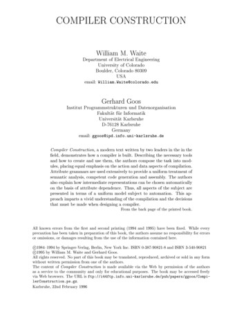
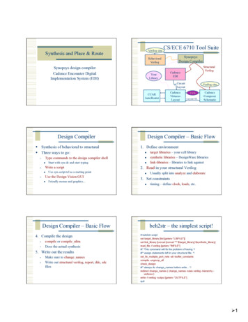
Verilog simSynthesis and Place & RouteCS/ECE 6710 Tool SuiteSynopsysDesign CompilerBehavioralVerilogSynopsys design compilerCadence Encounter DigitalImplementation System LayoutCCARAutoRouterDesign Compiler Synthesis of behavioral to structural Three ways to go:1.Type commands to the design compiler shell 2. 3.Start with syn-dc and start typingWrite a scriptUse syn-script.tcl as a starting pointUse the Design Vision GUI Friendly menus and graphics.4. Compile the design compile or compile ultraDoes the actual synthesis5. Write out the results Make sure to change namesWrite out structural verilog, report, ddc, sdcfilesLVSLayout-XLCadenceComposerSchematicDesign Compiler – Basic Flow1. Define environment target libraries – your cell librarysynthetic libraries – DesignWare librarieslink-libraries – libraries to link against2. Read in your structural Verilog Usually split into analyze and elaborate3. Set constraints Design Compiler – Basic FlowCadenceVirtuosoLayoutVerilog simtiming – define clock, loads, etc.beh2str – the simplest script!# beh2str scriptset target library [list [getenv "LIBFILE"]]set link library [concat [concat "*" target library] synthetic library]read file -f verilog [getenv "INFILE"]#/* This command will fix the problem of having */#/* assign statements left in your structural file. */set fix multiple port nets -all -buffer constantscompile -ungroup allcheck design#/* always do change names before write. */redirect change names { change names -rules verilog -hierarchy verbose }write -f verilog -output [getenv "OUTFILE"]quit 1
.synopsys dc.setupset SynopsysInstall [getenv "SYNOPSYS"]set search path [list . \[format "%s%s" SynopsysInstall /libraries/syn] \[format "%s%s" SynopsysInstall /dw/sim ver] \]define design lib WORK -path ./WORKset synthetic library [list dw foundation.sldb]set synlib wait for design license [list "DesignWare-Foundation"]set link library [concat [concat "*" target library] synthetic library]set symbol library [list generic.sdb]syn-script.tcl /uusoc/facility/cad common/local/class/6710/F11/synopsys#/* search path should include directories with memory .db files */#/* as well as the standard cells */set search path [list . \[format "%s%s" SynopsysInstall /libraries/syn] \[format "%s%s" SynopsysInstall /dw/sim ver] \!!your-library-path-goes-here!!]#/* target library list should include all target .db files */set target library [list !!your-library-name!!.db]#/* synthetic library is set in .synopsys dc.setup to be */#/* the dw foundation library. */set link library [concat [concat "*" target library] synthetic library]syn-script.tcl#/* Timing and loading information */set myPeriod ns !!10!!;# desired clock period (sets speed goal)set myInDelay ns !!0.25!!;# delay from clock to inputs validset myOutDelay ns !!0.25!!;# delay from clock to output validset myInputBuf !!INVX4!!;# name of cell driving the inputsset myLoadLibrary !!Lib!!;# name of library the cell comes fromset myLoadPin !!A!!;# pin that outputs driveWhat beh2str leaves out. Timing! No clock defined so no target speedNo input drive defined so assume infinite driveNo output load define so assume somethingsyn-script.tcl#/* below are parameters that you will want to set for each design */#/* list of all HDL files in the design */set myFiles [list !!all-your-structural-Verilog-files!! ]set fileFormat verilog;# verilog or VHDLset basename !!basename!!;# Name of top-level moduleset myClk !!clk!!;# The name of your clockset virtual 0;# 1 if virtual clock, 0 if real clock#/* compiler switches. */set useUltra 1;# 1 for compile ultra, 0 for compile#mapEffort, useUngroup are for#non-ultra compile.set mapEffort1 medium;# First pass - low, medium, or highset mapEffort2 medium;# second pass - low, medium, orhighset useUngroup 1;# 0 if no flatten, 1 if flattensyn-script.tcl#/* the following control which output files you want. They */#/* should be set to 1 if you want the file, 0 if not */set write v 1;# compiled structural Verilog fileset write ddc 0 ;# compiled file in ddc formatset write sdf 0 ;# sdf file for back-annotated timing simset write sdc 1 ;# sdc constraint file for place and routeset write rep 1 ;# report file from compilationset write pow 0 ;# report file for power estimate#/* Control the writing of result files */set runname struct ;# Name appended to output files 2
syn-script.tcl# analyze and elaborate the filesanalyze -format fileFormat -lib WORK myfileselaborate basename -lib WORK -updatecurrent design basename# The link command makes sure that all the required design# parts are linked together.# The uniquify command makes unique copies of replicated modules.linkuniquify# now you can create clocks for the designif { virtual 0 } {create clock -period myPeriod ns myClk} else {create clock -period myPeriod ns -name myClk}syn-script.tcl# Set the driving cell for all inputs except the clock# The clock has infinite drive by default. This is usually# what you want for synthesis because you will use other# tools (like SOC Encounter) to build the clock tree (or define it by hand).set driving cell -library myLoadLibrary -lib cell myInputBuf \[remove from collection [all inputs] myClk]# set the input and output delay relative to myclkset input delay myInDelay ns -clock myClk \[remove from collection [all inputs] myClk]set output delay myOutDelay ns -clock myClk [all outputs]# set the load of the circuit outputs in terms of the load# of the next cell that they will drive, also try to fix hold time issuesset load [load of [format “%s%s%s%s%s” myLoadLibrary \"/" myInputBuf "/" myLoadPin]] [all outputs]set fix hold myClksyn-script.tcl# now compile the design with given mapping effort# and do a second compile with incremental mapping# or use the compile ultra meta-commandif { useUltra 1 } {compile ultra} else {if { useUngroup 1 } {compile -ungoup all -map effort mapEffort1compile -incremental mapping -map effort mapEffort2} else {compile -map effort mapEffort1compile -incremental mapping -map effort mapEffort2}}syn-script.tcl# Check things for errorscheck designreport constraint -all violatorsset filebase [format "%s%s%s" basename " " runname]# structural (synthesized) file as verilogif { write v 1 } {set filename [format "%s%s" filebase ".v"]redirect change names { change names -rules verilog \-hierarchy -verbose }write -format verilog -hierarchy -output filename}# write the rest of the desired files. then quitUsing Scripts Modify syn-script.tcl or write your own syn-dc –f scriptname.tcl Make sure to check output!!!!Using Design Vision You can do all of these commands from thedesign vision gui if you like syn-dv Follow the same steps as the script Set libraries in your own .synopsys dc.setupanalyze/elaboratedefine clock and set constraintscompilewrite out results 3
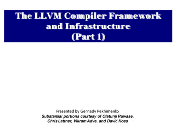
Setupanalyze/elaborateFile - AnalyzeFile - SetupLook at results.File - ElaborateDefine clockattributes - specify clockAlso look at other attributes.CompileTiming ReportsDesign - Compile UltraTiming - Report Timing Path 4
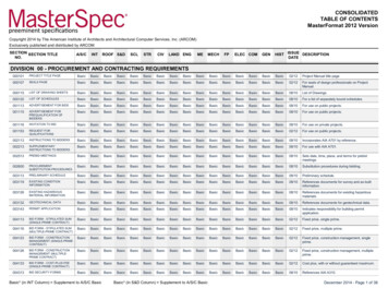
Write ResultsOr, use syn-dv after script. syn-dc –f mips.tcl results in .v, .ddc, .sdc, .rep files Read the .ddc file into syn-dv and use it toexplore timing.change namesFile - Save As.syn-dv with mips struct.vEndpoint slack.File - ReadTiming - Endpoint SlackPath SlackTiming - Path SlackEncounter Digital Implementation System Need structural Verilog, .sdc, library.lib,library.lef make a new dir for edi. design .conf is also very helpful use UofU soc.conf as starting point.And Default.view Usual warnings about scripting.UofU edi.tcl is the generic script ./local/class/6710/F11/cadence/EDI 5
cad-edi Flow1. Import Design .v, .sdc, .lib, .lef – can put this in a file.conf andDefault.view2. Power plan rings, stripes, row-routing (sroute)3. Placement place cells in the rows4. Timing optimization – preCTScad-edi Flow5. Synthesize clock tree 6. timing optimization – postCTS7. global routing NanoRoute8. timing optimization – postRoute9. Add filler cells10. Write out results Design Importuse your buf or inv footprint cells.def, soc.v, .spef, .sdc, .lefUsing a conf file Put the load information into a .conf file Load it up without having to re-type Also need a Default.view fileUofU edi.conf#global rda ############## Here are the parts you need to update for your ############### Your input is structural verilog. Set the top module name# and also give the .sdc file you used in synthesis for the# clock timing constraints.set rda Input(ui netlist){!!filename!!.v}set rda Input(ui topcell){!!TopCellName!!}set rda Input(ui timingcon file) {!!filename!!.sdc}UofU edi.conf## Leave min and max empty if you have only one timing library# (space-separated if you have more than one)set rda Input(ui timelib){!!filename!!.lib}set rda Input(ui timelib,min) {}set rda Input(ui timelib,max) {}### Set the name of your lef file or files# (space-separated if you have more than one).set rda Input(ui leffile) {!!filename!!.lef} 6
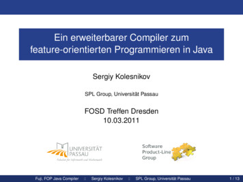
DesignImportDefault.view# Version:1.0 MMMC View Definition File# Do Not Remove Above Linecreate rc corner -name typical -preRoute res {1.0} -preRoute cap {1.0} preRoute clkres {0.0} -preRoute clkcap {0.0} -postRoute res {1.0} postRoute cap {1.0} -postRoute xcap {1.0} -postRoute clkres {0.0} postRoute clkcap {0.0}create library set -name 6710 typical -timing {!!your-lib-name.lib!!}create constraint mode -name typical -sdc files {!!your-cell-name.sdc!!}create delay corner -name typical -library set {6710 typical} -rc corner {typical}create analysis view -name typical -constraint mode {typical} -delay corner{typical}set analysis view -setup {typical} -hold {typical}FloorplanFloorplanSpecify - FloorplanSpecify - FloorplanPower Ringsand StripesFloorplanSpecify - FloorplanPower - Power Planning 7
Place cellsSroutetoconnectthingsupPlace - Place cells.Route - Sroutepre-CTS timing optimizationClock Tree Synthesisclock - create clock tree specTiming - Optimizationclock - Synthesize clock treeDisplay Clock Treepost-CTS optimization 8
NanoRouteRouted circuitRoute - NanoRoute - RouteRouted circuitpostRoute optimizationTiming - OptimizationAdd FillerWrite Results.Design - Save - NetlistDesign - Save - DEFPlace - Filler - Add. 9
Encounter Scripting Usual warnings – know what’s going on! Use top.tcl as a starting point And the other .tcl files it calls. EDI has a floorplanning stage that you maywant to do by hand write another script to read in the floorplan andgo from there. Use encounter.cmd to see the text versions ofwhat you did in the GUI.top.tcl# These set the percent utilization target (how dense should# the cells be placed), and the gap for routing between rows.# These are good starting values for small macros. Larger or# more complex macros will likely need a lowered usepct or# larger rowgap or both.set usepct 0.65 ;# percent utilization in placing cellsset rowgap 30 ;# gap between pairs of std cell rows# "aspect" sets the shape of the floorplan: less than 1.0# is landscape, greater than 1.0 is portrait, 1.0 is squareset aspect 0.60 ;# aspect ratio of overall celltop.tcl## Set the flag for SOC to automatically figure out buf, inv, etc.set dbgGPSAutoCellFunction 1# Import design and floorplan# If the config file is not named basename.conf, edit this line.loadConfig basename.conf 0commitConfigtop.tcl# set the basename for the config and floorplan files. This# will also be used for the .lib, .lef, .v, and .spef files.set basename “mips"# set the name of the filler cells - you don't need a list# if you only have oneset fillerCells FILL#set fillerCells [list FILL ######################### You may not have to change things below this line - but check!## You may want to do floorplanning by hand in which case you# have some modification to ############### Set some of the power and stripe parameters - you can change# these if you like - in particular check the stripe space (sspace)# and stripe offset (soffset)!set pwidth 9.9 ;# power rail widthset pspace 1.8 ;# power rail spaceset swidth 4.8;# power stripe widthset sspace 123 ;# power stripe spacingset soffset 120 ;# power stripe offset to first stripeset coregap 30.0 ;# gap between the core and the power railstop.tcl# source the files that operate on the circuitsource fplan.tcl ;# create the floorplan (might be done by hand.)source pplan.tcl ;# create the power rings and stripessource place.tcl ;# Place the cells and optimize (pre-CTS)source cts.tcl ;# Create the clock tree, and optimize (post-CTS)source route.tcl ;# Route the design using nanoRoutesource verify.tcl ;# Verify the design and produce output filesexit 10
fplan.tclputs "-------------Floorplanning---------------"## Make a floorplan - this works fine for projects that are all# standard cells and include no blocks that need hand placement.setDrawView fplansetFPlanRowSpacingAndType rowgap 2floorPlan -site core -r aspect usepct \ coregap coregap coregap coregapfit## Save design so farsaveDesign {BASENAME} fplan.encsaveFPlan {BASENAME}.fpputs "--------------Floorplanning done----------pplan.tclputs "-------------Power Planning----------------"puts "-------Making power rings------------------"## Make power and ground rings - pwidth microns wide# with pspace spacing between them and centered in the channeladdRing -spacing bottom pspace \-width left pwidth \-width bottom pwidth \.## Use the special-router to route the vdd! and gnd! netssroute -allowJogging 1# Save the design so farsaveDesign {BASENAME} pplan.encputs "-------------Power Planning done---------"Report Files topname Conn regular.rpt topname Conn special.rpt topname Geom.rptpplan.tclputs "-------------Power Planning----------------"puts "-------Making power rings------------------"## Make power and ground rings - pwidth microns wide# with pspace spacing between them and centered in the channeladdRing -spacing bottom pspace \-width left pwidth \-width bottom pwidth \-width top pwidth \-spacing top pspace \-layer bottom metal1 \-center 1 \-stacked via top layer metal3 \.top.tclRead the script.placepre-CTS optimizationclock tree synthesispost-CTS optimizationroutingpost-ROUTE optimizationadd fillerwrite out resultsRead back toicfbFile - Import - DEF Want 0 violations in all If you have 1 or 2 in the geometry you might beable to fix them easily in Virtuoso. 11
Change abstract to layout cellviewsImport VerilogEdit - SearchFile - Import - VerilogDRC, ExtractLVS.Schematic viewLVS ResultYay!Summary Behavioral - Structural - Layout Can be automated by scripting, but makesure you know what you’re doing on-line tutorials for TCL Google “tcl tutorial”Synopsys documentation for design compilerencounter.cmd (and documentation) for EDI End up with placed and routed core layout or BLOCK for later use. 12
Design Compiler Synthesis of behavioral to structural Three ways to go: 1. Type commands to the design compiler shell Start with syn-dc and start typing 2. Write a script Use syn-script.tcl as a starting point 3. Use the Design Vision GUI Friendly m