Transcription
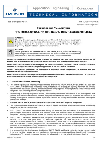
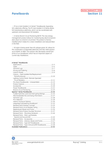
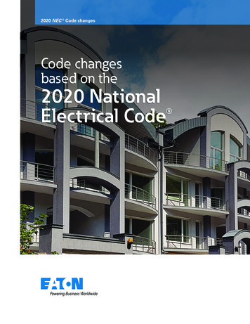
SECTION R507DECKSR507.1 Application. The provisions of this section shall provide prescriptive requirements for the design and construction of alluncovered, wood-framed, single-span exterior decks.R507.2 Requirements. Deck construction shall be capable of accommodating all vertical and horizontal loads in accordance withSection R301 and of transmitting the resulting loads to the supporting structural elements. Where a deck, or portions thereof, does notcomply with one or more of the requirements of this section, those portions shall be designed in accordance with Section R301.1.3,AF&PA/NDS and accepted engineering practice.BUILDING WALLHOLD-DOWNDEVICEJOISTHANGERSPOSTBEAMJOIST SPANLEDGERBOARDDECKINGJOISTCANTILEVEREND JOIRIMJOISTBEAMFOOTINGBEAM SPANCANTILEVERFor SI: 1 inch 25.4 mmBEAMCANTILEVERFIGURE R507.2DECK CONSTRUCTIONR507.3 Materials. Materials used in the construction of a deck shall meet the provisions of this section and as approved per Section112.2 of the Virginia Construction Code.R507.3.1 Preservative-treated lumber. Dimensioned lumber shall be identified in accordance with Section R502.1 andpreservative-treated in accordance with Section R317. All lumber in contact with the ground shall be identified as suitable forground contact.R507.3.2 Fasteners and connectors. All fasteners and connectors shall be in accordance with Section R317.3 and installed in perthe manufacturer. Fasteners and connectors exposed to salt water or located within 300 feet (90 m) of a salt-water shoreline shallbe stainless steel grade 304 or 316 in accordance with ASTM A 240. All nails shall be helical or annular and in accordance withASTM F 1667. Bolts and screws shall be in accordance with ANSI/ASME B18.6 and installed in accordance with AF&PA/NDS.R507.3.3 Flashing. Flashing shall be corrosion-resistant metal of minimum nominal 0.019 inch (0.5 mm) thickness or approvednon-metallic material.R507.3.4 Wood/plastic composites. Wood/plastic composites shall bear a label indicating the required performance levels anddemonstrating compliance with the provisions of ASTM D 7032 and shall be installed per the manufacturer.R507.4 Decking. Wood decking shall be nominal 2x6 lumber, span-rated decking or wood/plastic composites placed at an anglebetween 45 and 90 degrees to the joists with a ⅛ inch (3 mm) spacing between parallel members or per the manufacturer. Deckingshall be attached to each joist with (2)8d nails, (2)#8 wood screws or per the manufacturer. Decking shall be secured to the top of theband joist with 8d nails or #8 wood screws at 6 inches (152 mm) on center.R507.5 Joists. Joists shall be constructed in accordance Figure R507.5 with allowable spans in accordance with Table R507.5. Themaximum cantilever permitted shall be equal to ¼ of the joist span.Last revised October 22, 20121
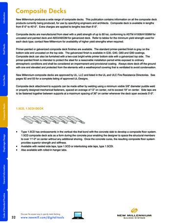
BUILDING WALLBUILDING WALLJOIST HANGERRIM JOISTBLOCKINGRIM JOISTBEAMBEAMJOISTPOSTPOSTPOSTJOIST SPANOPTIONALCANTILEVERBEAMLEDGER BOARDJOISTOPTIONALCANTILEVERATTACHED DECKJOIST SPANOPTIONALCANTILEVERFREE-STANDING DECKFIGURE R507.5DECK JOIST SPANSTABLE R507.5SPAN LENGTHS DECK JOISTSa(maximum spans for southern pine )JOISTSPACING(inches)121624JOIST SIZEJOISTS WITH NOCANTILEVERJOISTS WITHCANTILEVERS2x62x82 x 102 x 122x62x82 x 102 x 122x62x82 x 102 x -9"10'-9"15'-6"18'-0"5'-10"10'-2"13'-1"15'-5"For SI: 1 inch 25.4 mm, 1 foot 304.8 mma. Tabulated values are based on grade #2 and wet service.R507.5.1 Joist bearing. Joist bearing shall be provided in accordance with Section R502.6 and fastened to the beam inaccordance with Table R602.3(1) and to the joist hangers per the manufacturer. Joist hangers shall have a capacity as specified inTable R507.5.1.Table R507.5.1JOIST HANGER CAPACITYCAPACITYJOIST SIZE(pounds)2x63502x86002 x 107002 x 12800For SI: 1 pound 4.45 NR507.5.2 Joist ends. Rim joists of the same dimensioned lumber as the joists shall be secured to the end of each joist with (3)10dnails or (3)#10x3 inch long wood screws. Joist ends adjacent to the building wall of free-standing decks shall be blocked with fulldepth nominal 2x lumber toe nailed at each end with (3)10d nails.R507.5.3 Joist framing at chimney or bay window. Joist and header framing at chimneys, bay windows and other buildingprotrusions shall be constructed in accordance with Figure R507.5.3 and Table R602.3(1). The size of each header ply shall beequal to the specified joist size. Joist hangers shall be specifically designed for the number of plies identified.Last revised October 22, 20122
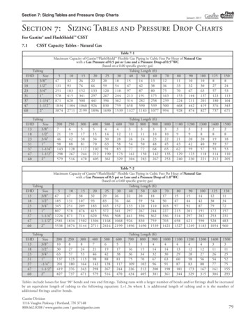
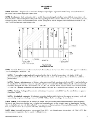
DECKING MAYEXTEND 6" MAXIMUM6'-0" MAXIMUM3' MAX.3-PLY JOISTCHIMNEYOR BAYWINDOWCHIMNEY ORBAY WINDOWLEDGERBOARDLEDGERBOARD2 LEDGER BOARD FASTENERSON EACH SIDE OF CHIMNEY ORBAY WINDOW3-PLY JOIST,EACH SIDE2-PLY HEADERPLAN VIEWSECTIONFor SI: 1 inch 25.4 mm, 1 foot 304.8 mmFIGURE R507.5FRAMING AT CHIMNEY OR BAY WINDOWR507.6 Beams. Beams shall be constructed in accordance Figure R507.6 with plies fastened in accordance with Table R602.3(1).Allowable beam spans shall be in accordance with Table R507.6. Beams shall be permitted to cantilever at each end up to ¼ of thebeam span. Splices of multi-span beams shall be located at interior post locations.JOISTSBEAM SPLICE ATINTERIOR POSTSBEAMPOSTOPTIONALBEAM SPANOPTIONALBEAM SPANCANTILEVERCANTILEVERFIGURE R507.6DECK BEAM SPANSTABLE R507.6aBEAM SPAN LENGTHSJOIST SPANBEAM 3)2x12 ' - ' - ' - 12'5'-0"6'-6"8'-5"9'-10"6'-3"8'-1"10'-6"12'-4"12' - 14'4'-8"6'-0"7'-9"9'-1"5'-10"7'-6"9'-9"11'-5"14' - 16'4'-4"5'-7"7'-3"8'-6"5'-5"7'-0"9'-1"10'-8"16' - 18'4'-1"5'-3"6'-10"8'-0"5'-2"6'-7"8'-7"10'-1"For SI: 1 inch 25.4 mm, 1 foot 304.8 mma. Tabulated values are based on southern pine, grade #2, wet service.R507.6.1 Beam bearing. Beam bearing shall be provided at posts in accordance with Section R502.6 and Figure R507.6.1. Postcaps, if used, shall have a minimum capacity of 5,000 pounds (22.25 kN) and shall be specifically manufactured for the beam andpost sizes.Last revised October 22, 20123
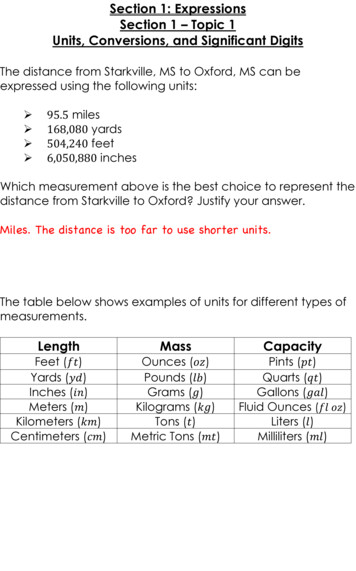
POST CAP PERMANUFACTURER2-PLY BEAMSON 6X6 POSTS3-PLY BEAM ON 6X6OR 2-PLY BEAM ON4X4 OR 6X6.2-21" DIAMETERTHROUGH-BOLTSWITH WASHERS6X6 POST6X6 OR4X4 POSTNOTCHPOSTPOST CAPNOTCHED POST (6X6 ONLY)For SI: 1 inch 25.4 mmFIGURE R507.6.1BEAM BEARINGR507.7 Posts. Posts shall be nominal 4x4 with a maximum height of 10 feet (3048 mm) or nominal 6x6 with a maximum height of18 feet (5486 mm). Post height shall be measured from the top of the footing to the underside of the beam. Post to beam connectionsshall be in accordance with Section R507.6.1, and post to footing connections shall be in accordance with Section R507.8.R507.8 Footings. Deck footings shall meet the requirements of Section R403, Figure R507.8 and Table R507.8.TABLE R507.8FOOTING SIZES 8'8' - 12'12' - 17'-5”FOOTING WIDTHSQUAREROUNDMINIMUMTHICKNESS 10'15"17"6"10' - 14'18"20"8"14' - 18'21"23"9" 10'19"21"8"10' - 14'22"24"10"14' - 18'26"28"11" 10'23"25"10"10' - 14'28"30"12"BEAM SPAN JOIST SPANFor SI: 1 inch 25.4 mm, 1 foot 304.8 mma. Tabular values are based on 1,500 pounds per square foot (71.8 kPa)load bearing pressure.PRE-MANUFACTURED CAST INPLACE POST BASE ANCHORCENTERED ON FOOTING12" DIAMETERCONCRETE STEMTHICKNESSDEPTH PERR507.8.1GRADEROUGHENCONCRETEJOINTWIDTHWIDTHFor SI: 1 inch 25.4 mmFIGURE R507.8DECK FOOTINGSR507.8.1 Footing depth. The minimum depth of footings shall meet the requirements of Section R403.1.4 and be of sufficientdepth such that the footing does not impose lateral pressure on adjacent building foundation walls.Last revised October 22, 20124
R507.9 Deck attachment to building. Decks shall be attached to the building wall in accordance with this section or shall be freestanding per Section R507.10. Deck ledger boards shall be nominal 2x lumber with a depth greater than or equal to the deck joists.R507.9.1 Attachment to resist vertical load. Decks shall be attached to the building wall to resist vertical load in accordancewith Sections R507.9.1.1 through R507.9.1.4.R507.9.1.1 Ledger board to band board. A ledger board shall be attached to a nominal 2x lumber band board with ½ inch(13 mm) diameter lag screws or through bolts with washers at a spacing specified in Section R507.9.1.4 and as shown in FigureR507.9.1.1. The exterior finish material shall be removed prior to installation of the ledger board. Flashing at a door thresholdshall be installed to prevent water intrusion from rain or melting ice and snow.EXTERIOR SHEATHINGSTUD WALL2X BAND BOARDFLASHINGDECK JOISTLAG SCREWS OR BOLTSFLOOR FRAMINGFOUNDATION WALLJOIST HANGERLEDGER BOARDFIGURE R507.9.1.1LEDGER BOARD TO BAND BOARD ATTACHMENTR507.9.1.2 Ledger board to solid foundation wall. A ledger board shall be attached to a concrete or solid masonryfoundation wall with approved ½ inch (13 mm) diameter expansion anchors at a spacing specified in Section R507.9.5 and asshown in Figure R507.9.2. Expansion anchors shall be installed per the manufacturer.EMBEDMENT PERMANUFACTURERCONCRETE OR SOLIDMASONRY WALLDECK JOISTAPPROVED EXPANSIONANCHORSJOIST HANGERLEDGER BOARDFIGURE R507.9.2LEDGER BOARD TO SOLID FOUNDATION WALL ATTACHMENTR507.9.1.3 Alternate connections. An approved engineered wood rim board with a minimum thickness of 1 inch (25 mm)shall be permitted to substitute for a 2x lumber band board provided it has designed and manufactured to support a deck. Aledger board attachment to a masonry or stone veneer, hollow masonry wall, ribbon board of open web floor trusses, bandboard of a cantilevered floor and other conditions not addressed herein shall be designed in accordance with acceptedengineering practice, or the deck shall be free-standing in accordance with Section R507.10.R507.9.1.4 Fastener placement. Ledger board fasteners shall be placed in accordance with Figure R507.9.1.4 and spaced inaccordance with Table R507.9.1.4 to resist vertical load.Last revised October 22, 20125
2" MIN.TYPICAL SPACING5.5" MIN. FOR 2x86.5" MIN. FOR 2x107.5" MIN. FOR 2x122" MIN.2" MIN.APPROVED FASTENERS;STAGGER IN 2 ROWSFor SI: 1 inch 25.4 mmFIGURE R507.9.1.4LEDGER BOARD FASTENER PLACEMENTTABLE R507.9.1.4FASTENER SPACINGFASTENERLag screwsBAND BOARDaThrough boltsExpansion anchorsJOIST SPAN 6'6'-8'8'-10'10'-12'12'-14'14'-16'16'-18'1" min. engineeredwood product24"18"14"12"10"9"8"2x lumber30"23"18"15"13"11"10"1" min. engineeredwood product24"18"14"12"10"9"8"2x or SI: 1 inch 25.4 mm, 1 foot 304.8 mma. The tip of the lag screw shall fully extend beyond the inside face of the band board.R507.9.2 Attachment to resist horizontal load. Decks shall be capable of resisting lateral load equivalent to a 1,500 pound(6672 N) tension force at each end of the deck ledger in accordance with this section or accepted engineering practice.R507.9.2.1 Connection at parallel joists. Where floor joists and deck joists are parallel, provide a hold-down or similartension device with a minimum capacity of 1,500 pounds (6672 N) at each end joist as shown in Figures R507.2 andR507.9.2.1(1). Where floor joists and deck joists do not align, threaded rods shall be permitted to offset as shown in FigureR507.9.2.1(2) and per the manufacturer of the hold-down or tension device system. Reinforcing angles shall have a minimumcapacity of 375 pounds (1668 N) and shall not be required where the floor sheathing is attached to the floor joists with fastenersat 6 inches (152 mm) on center.2 REINFORCINGANGLE EACHSIDE OF JOIST4" MAX.HOLD-DOWN ORSIMILAR TENSIONDEVICEFLOOR JOISTDECK ENDJOIST12"DIAMETERTHREADED RODFor SI: 1 inch 25.4 mm, 1 foot 304.8 mmFIGURE R507.9.2.1(1)CONNECTION AT PARALLEL JOISTSLast revised October 22, 20126
FLOOR JOISTPER MANUFACTUREROFFSET PERMANUFACTURERBAND BOARDLEDGER BOARDEND JOISTFIGURE R507.9.2.1(2)OFFSET AT PARALLEL JOISTSR507.9.2.2 Connection at perpendicular joists. Where floor joists and deck joists are perpendicular, provide a hold-down orsimilar tension device with a minimum capacity of 1,500 pounds (6672 N) at each end joist and blocking between floor joists asshown in Figure R507.9.2.2. Reinforcing angles shall have a minimum capacity of 375 pounds (1668 N) and shall not berequired where the floor sheathing is attached to the floor joists with fasteners at 6 inches (152 mm) on center.2 REINFORCINGANGLES EACHSIDE OF BLOCKING4" MAX.HOLD-DOWN ORSIMILAR TENSIONDEVICEDECK JOISTTWO BAYS FULL HEIGHT 2XBLOCKING; ATTACH WITH(3)10d NAILS EACH END12" DIAMETERTHREADED RODFLOOR JOISTFor SI: 1 inch 25.4 mmFIGURE R507.9.2.2LATERAL SUPPORT WHERE INTERIOR JOIST PERPENDICULAR TO DECKR507.9.2.3 Connection at solid foundation wall. Where decks are attached to concrete or solid masonry foundation walls,provide a hold-down or similar tension device as shown in Figure R507.9.2.3. Post-installed adhesive anchor system shall havea pull-out capacity of 1,500 pounds (6672 N). Embedment length and installation shall be per the manufacturer. Holes throughthe ledger board shall be protected to prevent water intrusion.HOLD-DOWN ORSIMILAR TENSIONDEVICEEMBEDMENT PERMANUFACTURERCONCRETE OR SOLIDMASONRY WALLDECK JOISTPOST-INSTALLEDADHESIVE ANCHORSYSTEM12"DIAMETERTHREADED RODFor SI: 1 inch 25.4 mmFIGURE R507.9.2.3LATERAL SUPPORT TO SOLID FOUNDATION WALLLast revised October 22, 20127
R507.10 Free-standing decks. As shown in Figure R507.10, free-standing decks shall have an additional beam and posts adjacentthe building exterior wall in place of a ledger board attachment. The beam shall be sized in accordance with Section R507.6 and shallbe located adjacent the exterior wall or at a maximum distance equal to the allowable joist cantilever.2x BLOCKINGBETWEEN JOISTSRIM JOISTJOIST CANTILEVERBUILDING FOUDATIONWALLBEAMFOOTINGS SHALL NOT IMPOSELATERAL LOAD ON BUILDINGFOUNDATION WALLJOISTDIAGIONALBRACINGFIGURE R507.10FREE-STANDING DECKR507.10.1 Diagonal bracing. Diagonal bracing shall be installed on free-standing decks greater than 30 inches (762 mm) abovegrade in accordance with Figure R507.10.1. Bracing shall be placed at each post location in the parallel and perpendiculardirections to the beam. Bracing shall be a minimum of nominal 2x4 lumber and shall be fastened to framing with one ½ inch (12mm) diameter through bolt with washers at each end. Where bracing does not align with a joist, a 2x10 nailer shall be fastened tothe underside of joists with 2-10d nails at each joist. Bracing shall be fastened to the nailer with 3-10d toe nails.2'2'2x10 NAILER WHERE BRACINGDOES NOT ALIGN WITH A JOISTBEAM2'BEAM2'BRACINGJOISTS AT POSTLOCATIONSTHROUGH-BOLTWITH WASHERS,TYPICALBRACING PARALLEL TO BEAMBRACING PARALLEL TO JOISTSFor SI: 1 foot 304.8 mmFIGURE R507.10.1FREE-STANDING DECK DIAGONAL BRACINGR507.12 Deck guards. Deck guards shall be constructed in accordance with Section R312, Figure R507.12 and this section.Alternate guards and guard systems shall comply with Section R507.2.Last revised October 22, 20128
6' MAX.4X4 POST,DO NOT NOTCH2X2 PICKETS; MAY BE PLACED ONEITHER SIDE OF GUARD36" MIN.2X6 RAIL CAP2 21" - 5"2X4 TOP AND BOTTOM; MAYBE PLACED ON EITHER SIDEOF GUARD POST; ATTACH TOPOST WITH (2) 8d OR (2) #8WOOD SCREWS(2) 21" DIAMETERTHROUGH-BOLTS ANDWASHERS CENTERED2" MIN. TOP& BOTTOMATTACH PICKETS AT TOPAND BOTTOM WITH (1) #8WOOD SCREW OR (2) 8dNAILSFor SI: 1 inch 25.4 mm, 1 foot 304.8 mmFIGURE R507.12DECK GUARDR507.12.1 Guard post attachment. Guard posts shall be attached to the inside or outside face of the rim joists or end joists inaccordance with Figure R507.12.1(1) and R507.12.1(2). Hold-down anchors shall have a minimum capacity of 1,800 pounds(8006 N).FASTENERS PERHOLD-DOWNMANUFACTURERGUARDPOSTEND JOISTHOLD-DOWNANCHORSGUARD POSTEND JOIST2X BLOCKING BETWEENJOISTS; TOE NAIL WITH(3)10d NAILS EACH SIDEBLOCKINGSECTIONPLANFIGURE R507.12.1(1)GUARD POST TO END JOISTGUARD POSTHOLD-DOWN ANCHORHOLD-DOWN ANCHORJOISTGUARD POSTALIGN GUARDPOST AT JOISTLOCATIONSFASTENERS PERHOLD-DOWNMANUFACTURERRIM JOISTRIM JOISTHOLD-DOWN ANCHORJOISTAT JOIST LOCATIONRIM JOISTSECTIONBETWEEN JOISTSPLANFIGURE R507.12.1(2)GUARD POST TO RIM JOISTR507.13 Deck stairs. Deck stairs shall be constructed in accordance with this section and Section R311.7. Where a flight of stairshas a vertical rise greater than that required per Section R311.7.3, an intermediate landing shall be provided in accordance withSection R311.7.6 and designed as a free-standing deck in accordance with Section R507.10.Last revised October 22, 20129
R507.13.1 Stair stringers. Stair stringers shall be constructed of sawn nominal 2x12 members at 18 inches (457 mm) on centerwith a throat dimension of 5 inches (127 mm) and a maximum span length as shown in Figure R507.13.1. Stairs with a widthequal to 36 inches (914 mm) shall be permitted to be constructed with two solid 2x12 stringers with a maximum span length asshown in Figure R507.13.1.N.MI5"MAX. SPAN 7'-0"MAX. SPAN 16'-6"SAWN STRINGERSOLID STRINGERFor SI: 1 inch 25.4 mm, 1 foot 304.8 mmFIGURE R507.13.1STAIR STRINGER REQUIREMENTSR507.13.2 Stringer bearing. Stringers shall bear on joist hangers attached to the deck structure and on footings at grade inaccordance with Figure R507.13.2. Joist hangers shall be specifically designed to accommodate sloped connections and shall havea minimum capacity of 625 pounds (2780 N). Reinforcing angles at rim joist locations only shall have a minimum capacity of 325pounds (1446 N).RIM JOIST OREND JOISTGUARD POST,IF REQUIREDSLOPED JOIST HANGERSTRINGERREINFORCINGANGLES AT RIMJOIST10" ROUND OR 8"SQUARE FOOTINGDEPTH PERR507.8.1GRADEFIGURE R507.13.2STRINGER BEARINGR507.13.3 Treads and risers. Stair treads shall be constructed in accordance with this section and Figure R507.13.3. Treadsshall be composed of nominal 2x6 lumber. Treads of stairs constructed with solid stringers shall be permitted to be composed ofspan rated decking. Risers shall be permitted to be composed of nominal 1x lumber. Openings in risers shall not allow the passageof a 4 inch (102 mm) diameter sphere.36"2X6 TREAD2X6 OR SPANRATED DECKINGSOLIDSTRINGERSAWNSTRINGER18" MAX.18" MAX.SAWN STRINGER2X4 LEDGER FASTENEDWITH (4)10d NAILS OR(4)#8X3" LONG SCREWSSOLID STRINGERFor SI: 1 inch 25.4 mmFIGURE R507.13.3TREAD REQUIREMENTSR507.13.4 Stair guard. Guards for stairs shall be required per Section R312.1.1 and constructed in accordance with SectionR507.12. The attachment of a stair guard post to the stringers shall be constructed in accordance with Figure R507.13.4.Last revised October 22, 201210
6' MAX.STRINGERSFULL DEPTH 2X BLOCKINGBETWEEN STRINGERS; ATTACHWITH (3)10d NAILS EACH SIDEGUARD POSTSTRINGERFor SI: 1 foot 304.8 mmFIGURE R507.13.4STAIR GUARD CONNECTIONLast revised October 22, 201211
HOLD-DOWN DEVICE BUILDING WALL For SI: 1 inch 25.4 mm FIGURE R507.2 DECK CONSTRUCTION R507.3 Materials. Materials used in the construction of a deck shall meet the provisions of this section and as approved per Section 112.2 of the Virginia Construction