Transcription
2nd AIAA "Unmanned Unlimited" Systems, Technologies, and Operations — Aerospac15 - 18 September 2003, San Diego, CaliforniaAIAA 2003-6578EVOLUTION OF A MARS AIRPLANE CONCEPT FOR THE ARES MARS SCOUTMISSIONMark D. Guynn* and Mark A. Croom†, NASA Langley Research Center, Hampton, VA 23681Stephen C. Smith‡, NASA Ames Research Center, Moffett Field, CA 94035Robert W. Parks§, Aurora Flight Sciences, Manassas, VA 20110Paul A. Gelhausen¶, AVID LLC, Yorktown, VA 23692ABSTRACTARES (Aerial Regional-scale Environmental Survey ofMars) is a proposed Mars Scout mission using anairplane to provide high-value science measurements inthe areas of atmospheric chemistry, surface geology andmineralogy, and crustal magnetism. The use of anairplane for robotic exploration of Mars has beenstudied for over 25 years. There are, however,significant challenges associated with getting anairplane to Mars and flying through the thin, carbondioxide Martian atmosphere. The traditional wisdomfor aircraft design does not always apply for this type ofvehicle and geometric, aerodynamic, and missionconstraints result in a limited feasible design space.The ARES airplane design is the result of a conceptexploration and evolution involving a number of tradestudies, downselects, and design refinements. Industry,university, and NASA partners initially proposed anumber of different concepts, drawing heavily on pastMars airplane design experience. Concept downselectswere conducted with qualitative evaluation and highlevel analyses, focused on the most importantparameters for the ARES mission. Following asuccessful high altitude test flight of the basicconfiguration, additional design refinement led to thecurrent design. The resulting Mars airplane conceptenables the high-value science objectives of the ARESmission to be accomplished while also fulfilling thedesire for a simple, low-risk design.INTRODUCTIONThe vision of winged vehicles flying through theMartian atmosphere has existed for at least 50 years. InWernher von Braun’s book The Mars Project, firstpublished in the early 1950’s, human explorers of Marsare transferred from orbit to the surface using landinggliders.1 For over 25 years serious consideration hasbeen given to the use of an unmanned Mars airplane asa science platform. The idea of performing scientificobservations on Mars using an airplane has persisted*Aerospace Engineer; Senior Member AIAA.ARES Airplane Chief Engineer; Member AIAA.‡Research Engineer; Associate Fellow AIAA.§Senior Aircraft Designer; Member AIAA.¶Chief Technology Officer; Senior Member AIAA.†because of the clear advantages associated with anairborne platform.Just like on Earth, airborneobservations would complement ground-based andspace-based observations, permitting higher resolutionthan possible with space-based platforms and greatercoverage than possible with ground-based platforms.An airplane offers an additional advantage over otherairborne platforms (e.g., balloons) in that it can bemaneuvered to specific locations of interest. There areseveral technical challenges associated with a Marsairplane, however.The first and foremost consideration in Mars airplanedesign is the nature of the Martian atmosphere.Atmospheric density near the Martian surface isroughly equivalent to an altitude of 100,000 feet onEarth. With such a thin atmosphere, generating enoughlift to support the airplane weight is difficult and wingloading has to be small. Fortunately, the airplaneweight is only 38% of what it would be on Earth dueto the lower gravity on Mars. Nevertheless, anemphasis must still be placed on minimizing airframeand system masses in order to achieve the required lowwing loading. The flight conditions on Mars are unlikethose normally encountered by Earth aircraft. The lowatmospheric density leads to a high cruise velocity, buta low flight Reynolds number. Since the speed ofsound on Mars is lower than on Earth, transonicaerodynamic effects are encountered at a lower flightspeed. Special care must be taken in the aerodynamicdesign to avoid dramatic losses in lift and/or dramaticincreases in drag associated with the low Reynoldsnumber, high Mach number flight conditions. Lowatmospheric density also presents problems withgenerating thrust. For an Earth airplane thrust isusually generated by transferring momentum tofreestream air. The lower the atmospheric density, theless mass available for momentum transfer and the lessthrust that can be generated for a given size propulsionsystem. A Mars airplane propeller, for example, wouldhave to be larger than a typical Earth propeller togenerate the same amount of thrust. A lack ofappreciable amounts of atmospheric oxygen (O2)presents another propulsion issue. Most Earth airplanesuse air-breathing propulsion systems, relying on O2from incoming air as an oxidizer to release energy1American Institute of Aeronautics and AstronauticsThis material is declared a work of the U.S. Government and is not subject to copyright protection in the United States.
stored in the on-board fuel. This approach is not viablein the mainly carbon dioxide (CO2) Martianatmosphere. Numerous concepts exist for non-airbreathing propulsion systems. Unfortunately, theygenerally have much higher fuel consumption and/oradditional system mass and complexity compared toconventional airplane propulsion. This makes theefficiency and mass of the rest of the airplane systemeven more critical.In addition to the challenge of generating sufficient liftand thrust to fly an airplane through the Martianatmosphere, there are challenges associated with gettingthe airplane to Mars. The geometric arrangement bestsuited for efficient, stable atmospheric flight is muchdifferent from that best suited for launch andatmospheric entry. Efficient packaging of the aircraft iscritical to provide sufficient wing area (lift capability)within the geometric constraints of the launch and entryvehicles. Generally, the airplane must be stowed in anon-flight configuration during the transit to Mars.Once at Mars the airplane must be deployed into itsflight configuration. If a mid-air deployment approachis used, not only must the aircraft successfully deploy,but there is also a transition from “falling” to flying thathas to be accomplished. This mid-air conversion fromthe stowed configuration to flight, in which the airplanemust take shape, orient itself, and execute a pulloutmaneuver, is a critical design point.2Mars airplane design involves a number of challengesthat are not encountered in the design of Earthairplanes. However, over the decades in which thedream of flying on Mars has endured, numerous studieshave investigated options for overcoming thesechallenges. In addition, there have been importanttechnology advances and successes in the related fieldof high-altitude Earth airplanes which can be leveragedfor a successful Mars airplane design. Following abrief look at Mars airplane design from a historicalperspective, this paper describes the evolution of Marsairplane designs for the ARES (Aerial Regional-scaleEnvironmental Survey of Mars) Mars Scout mission.Through a combination of concept exploration and pastdesign experience, a viable Mars airplane, ARES-1,was developed in 2002 for the ARES Step 1 Mars Scoutproposal. The ARES mission was one of four MarsScout proposals selected in December 2002 forcontinued study. Additional maturation and refinementof the airplane design led to an improved design,ARES-2, which was detailed in the ARES ConceptStudy Report submitted to the Mars Scout program inMay 2003.HISTORICAL PERSPECTIVEIn the late 1970’s, with funding and direction from theJet Propulsion Laboratory (JPL), DevelopmentalSciences, Inc. (DSI) conducted what was probably themost comprehensive early investigation of thefeasibility of a Mars airplane.3 This investigation grewout of a recognition that the remotely piloted “MiniSniffer” aircraft developed at NASA Dryden for highaltitude Earth atmospheric research could serve as aprecursor to a Mars airplane. One of the uniquefeatures of the “Mini-Sniffer” concept was a non-airbreathing hydrazine fueled engine developed by JamesAkkerman. The DSI study investigated a number ofairplane and mission design options. The final missionscenario selected was elaborate, involving 3 spacecraftcarrying 4 airplanes each. Once at Mars the spacecraftwere to be used as communication satellites to provideglobal communication coverage for the airplanes. TheDSI airplane (named “Astroplane” by DSI) had awingspan of 21 m, wing area of 20 m2, and a nominalmass of 300 kg. A complex folding scheme, whichincluded 6 wing folds, 3 fuselage folds and a foldingpropeller, was necessary to fit the Astroplane into a3.8m Viking-like aeroshell. The DSI study wasterminated in 1978 following a NASA decision topursue other Mars exploration priorities. Although theconcept was not carried forward, the resulting report3documents the challenges of flying on Mars andpossible approaches for meeting those challenges.Since the DSI study there have been several NASA,industry, and university studies of Mars airplanemissions. Of particular importance to the ARES projectwas a recent NASA led effort to develop an airplanemission as part of the Mars Micromission Project. Thegoal of the Mars Micromission Project was to send aseries of small, low-cost spacecraft to Mars. Thespacecraft were to be launched as secondary payloadson Ariane 5 commercial launches. This small-scale,low-cost approach to Mars exploration stands in starkcontrast to the ambitious and expensive missionenvisioned in the DSI Mars airplane study. A relativelyshort, but intense, Mars airplane concept developmenteffort was initiated in February 1999 by Dan Goldin’s(then NASA Administrator) challenge to fly an aircrafton Mars on the 100th anniversary of the Wright brothershistoric flight at Kitty Hawk.4 With a mandate from theNASA Administrator, a large number of personnelacross several NASA research centers were assigned tothe task and a significant amount of work wasaccomplished in a very short period of time. In order tofit the Ariane 5 secondary payload ring, aeroshelldiameter was limited to just 0.8 m. The small sizemade efficient packaging a critical issue, both in terms2American Institute of Aeronautics and Astronautics
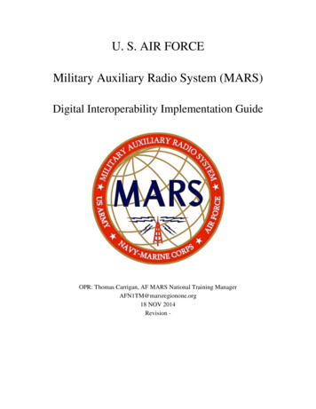
of packaging the airplane in the aeroshell andpackaging the airplane systems in the airplane.Significant effort was directed at exploring differentpackaging schemes to fit the small aeroshell diameter.Aerodynamic design of the Micromission airplane(referred to as the Mars Airplane Package or MAP inMars Micromission nomenclature) was also a challengedue to the extremely low Reynolds number, highsubsonic Mach number flight regime. Initial conceptexploration was conducted by teams at Ames ResearchCenter,5 Dryden Flight Research Center and LangleyResearch Center. Concepts were also later developedby industry teams. One of the NASA developed MAPairplane concepts is illustrated in Figure 1. This rocketpowered airplane had a design mass of 19 kg with apayload mass allowance of 2.6 kg. Wing area was 0.67m2 and wing span was 1.73 m. The nominal cruiseMach number was 0.65 with a wing Reynolds numberof around 50,000. The fuel load of 3.2 kg provided 20min of powered flight and a powered range of 200 km.Aircraft performance and potential science return wasseverely limited by low maximum lift and high dragresulting from the low Reynolds number, high Machnumber flight condition. However, the goal of theMAP was not to return extensive amounts of sciencedata, but to demonstrate the ability to use a Marsairplane as a science platform. The Mars airplaneMicromission project was cancelled in November 1999.Although the ARES airplane is much larger than theMAP airplane, the analysis and testing done during theMAP project provided a strong foundation for theARES airplane design.DESIGN REQUIREMENTS AND PHILOSOPHYUnlike the MAP project, the focus of the ARES missionis not on the airplane but on Mars science. Theregional-scale, high-resolution measurements fromARES will provide fundamental new understanding ofthe nature and variability of the Mars atmosphere,surface, and interior.6 Although flying an airplane onMars is certainly an exciting aeronautical event, from amission perspective the airplane is simply a platformwith which to accomplish the science objectives. Thegeneral design philosophy that was adopted for theARES airplane was to look for the simplest, mostrobust means to meet the science requirements.Minimizing the risk, complexity, and cost of theairplane system was a primary driver in designdecisions. For example, the risk associated with acomplex folding scheme such as used for the DSIAstroplane would not be acceptable for the ARESairplane. Extensive airplane technology developmentwould be counter to the low-risk, science focusedARES philosophy. The fact that the ARES mission waspart of a competitive selection process also influenceddesign decisions. To have a successful proposal theairplane design needed to not only meet the missionrequirements but also be robust and practical from theperspective of the proposal evaluators.Some specific requirements for the ARES airplanedesign are listed in Table 1. The aeroshell size is muchlarger than for the 1999 Micromission airplane. Thisenables a larger airplane and flight in a morepredictable and better understood flow regime, althoughstill significantly different from that typical of an Earthaircraft.Table 1. ARES Airplane Design Requirements Fit within a 2.65 m diameter Viking-derivativeaeroshell shape (max. internal diameter of 2.48 m) Survive G, radiation, and thermal environmentsassociated with launch, 12 month transit to Mars,and atmospheric entry Provide a stable observation platform- maintain sub-pixel smear in worse caseturbulence Autonomously navigate a specified ground track- altitude 1-2 km above ground level (AGL),variation of 10% over 10 km- range 500 km Telemetry science data collected during flight- maneuvering restricted to maintain comm. link- useful endurance limited by comm. windowThe return of science data to Earth is an importantconsideration for the mission. Unlike Earth, Mars doesnot have a constellation of satellites which can providea continuous, high data rate communication link. In theDSI mission, global communication coverage was to beprovided by inserting the three carrier spacecraft inorbit.3 In the ARES mission architecture, the primarycommunication link is provided by the carrierspacecraft executing a fly-by maneuver. The fly-bytrajectory, airplane flight path, and transmitter powerestablish a limit on the total data volume which can betransmitted from the airplane to the carrier spacecraft,and ultimately to Earth. The limited data volume hasan important consequence for the airplane design.Although one is inclined to strive for maximum rangeand endurance, collecting data which cannot bereturned to Earth does not have value. There is a point,therefore, at which additional airplane performancemay not yield any increase in the scientific value. Thisagain leads to finding a design that is “good enough” toperform the mission, as opposed to maximizingperformance. (Note: The concept of post-flight datatransmission was considered for the ARES mission and3American Institute of Aeronautics and Astronautics
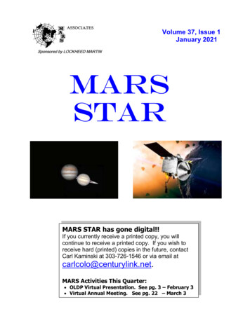
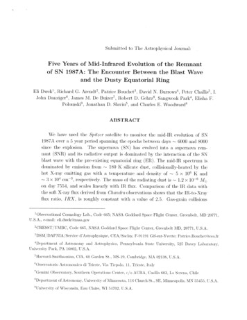
rejected due to the large mass penalty associated with asurvivable data package and the increased risk of lossof data.)ARES AIRPLANE CONCEPT EXPLORATIONThe current ARES airplane design, referred to asARES-2, is illustrated in Figure 2. This design is theresult of a concept exploration and evolution involvinga number of trade studies, downselects, and designrefinements. The ARES airplane concept developmentteam encompassed a broad range of expertise acrossNASA (Langley, Ames, and Glenn Research Centers),industry (Aurora Flight Sciences), and academia(Stanford University and Massachusetts Institute ofTechnology (MIT)). Ideas and concepts were generatedand evaluated by team members both individually andcollectively. Major areas of consideration during theconcept development included: aeroshell packagingapproach, propulsion, tail arrangement, and winggeometry.Methodology for Concept ExplorationEvaluation of a wide variety of concepts, to varyinglevels of detail, guided the concept selection process.Comparative aerodynamic analysis focused on theprimary design drivers for the ARES mission: stabilityand control, maximum lift, and lift-to-drag ratio (L/D).General stability and control characteristics wereassessed using an inviscid, vortex lattice analysis code,VORVIEW. VORVIEW was developed at NASAAmes and is an enhancement of the VORLAX codedeveloped by Lockheed in the 1970’s.7TheVORVIEW graphical user interface allows the user tointeractively define control surface locations and thevortex lattice paneling. Stability and control derivativescan be calculated using an automated routine whichperturbs flight conditions and control surfacedeflections.Input geometry for VORVIEW wasgenerated with the Rapid Aircraft Modeler (RAM)aircraft geometry tool also developed at NASA Ames.8While a vortex lattice analysis cannot capture viscouseffects on the configuration stability and control, it wasan appropriate tool for configuration screening andassessing fundamental stability and control issues.Maximum lift capability and L/D characteristicsdirectly impact the ability of the design to meet thescience mission goals. Prediction of maximum liftcoefficient (CLmax) and drag requires methods whichencompass viscous flow effects. Unfortunately, typical“handbook” type estimates for these parameters do notadequately reflect the unusual Mach and Reynoldsnumber flight regime of a Mars airplane. Of particularimportance is the potential for unusual boundary layerbehavior (such as separation bubbles) which cansignificantly impact the lift and drag characteristics.Since it was impractical to perform a viscous, 3-Dcomputational fluid dynamics analysis for eachconfiguration considered, a coupled 2-D/3-D analysisapproach was employed. Airfoil section characteristicswere estimated using the MSES code developed byMark Drela of MIT.9 MSES couples a streamwiseEuler discretization of the flow with an integralboundary layer formulation. It has been previouslyused for both low Reynolds number and transonicapplications. Good agreement between MSES and 2-DNavier-Stokes solutions has been demonstrated atARES airplane flow conditions.10The airfoilcharacteristics were extended to 3-D aerodynamicpredictions using a non-linear Weissinger methoddeveloped at UC-Davis.11 This method is similar to anon-linear lifting line method, such as presented byAnderson.12 The method combines viscous airfoil data(from wind tunnel or computational analysis such asMSES) with inviscid, 3-D lifting surface theory.Viscous drag and pitching moment effects are capturedin a stripwise integration using the input viscous airfoilcharacteristics. When a local Cl reaches Clmax at somespan location, the solution procedure usually becomesunstable and analysis at higher angles of attack is notpossible. The total configuration CL at this point wasconsidered the approximate CLmax, since local Cl Clmaxis an often-used criterion for estimating CLmax inconceptual design. Since drag results from the nonlinear Weissinger code only include the lifting surfaces,traditional estimation techniques were used to add dragfor other components.Early comparative analysis of the total mass and overallmission performance of various design options wasconducted using spreadsheet-based analysis. Airframeand system masses were estimated based on previousstudies and simple relationships. Propulsion systemcharacteristics were based on data for existing systemsor on expert opinion. Range performance for a specificfuel (or battery) mass was determined through a timestep integration.After the concept was selected, higher fidelity analysismethods were applied, including finite elementstructural analysis, 3-D computational fluid dynamicsanalysis, and six degree-of-freedom airplane missionsimulations.Aeroshell Packaging ApproachThe ARES airplane is delivered to Mars in the Vikingderivative aeroshell shape shown in Figure 3. This4American Institute of Aeronautics and Astronautics
shape is not ideal in terms of maximizing airplane sizeand performance, but was selected because of aeroshelldesign heritage.Packaging in the aeroshell iscomplicated by a parachute canister which extendsthrough the middle of the aeroshell interior and sixseparation fittings around the perimeter, i.e. where thebackshell and heat shield of the aeroshell attach.The lowest risk packaging approach is to simply makethe airplane small enough to fit inside the aeroshell inthe flight configuration. Unfortunately, the resultingwing area for a 2.65 m aeroshell limits the maximumairplane mass to values that are too low to meet theARES science payload and range requirements. Inorder to get sufficient wing area some type of airplanestowage in the aeroshell is necessary.Using a non-rigid wing takes most advantage of theavailable aeroshell volume. One possibility is aRogallo type parawing.13 Another concept, which hasbeen demonstrated on Earth, is an inflatable wing.14Flexible or inflatable structure could also be used to addwing area to a rigid structure. The main issue with nonrigid wing concepts was the additional risk entailedover a conventional structure. Of particular concernwas the performance of flexible materials after beingexposed to a cold environment for the approximatelyone year transit to Mars. Although this issue couldlikely be resolved, the need for qualification andperhaps development of appropriate materials wasdeemed an unacceptable additional program risk.A conventional rigid structure can be built with spacequalified materials. Options for stowage of rigidstructures include folding or telescoping mechanisms.A number of past space systems have used telescopingmechanisms. There is a history, however, of problemswith these mechanisms. Spring-loaded folds wereconsidered the simplest, lowest risk packagingapproach. Since there is still risk involved in theaircraft unfolding, minimizing the number of folds wasa design objective. The basic wing folding scheme wasbased on one developed during the MAP project inwhich the outer wing panels are folded on top of eachother as illustrated in Figure 4. This approach allows alarge wing area to be obtained with only two wing folds(one on each side).PropulsionLow atmospheric density and the lack of appreciableamounts of atmospheric O2 complicate propulsion for aMars airplane and lead to consideration ofunconventional (from an Earth airplane perspective)propulsion options. There are several approaches fordealing with a lack of atmospheric O2. Use of amonopropellant fuel or carrying both fuel and oxidizeron-board enables combustion without atmospheric O2.(Note that since one of the ARES science objectives ismeasurement of trace atmospheric gases, the missionmust be planned such that combustion exhaust productsdo not contaminate these measurements.) Anotherapproach is to use energy from some type of on-boardbattery or nuclear device. Energy can also be obtainedfrom an off-board source such as solar energy or adirected energy system. Solar powered airplanes haveto be quite large to collect sufficient solar power andtypically have small payload mass fractions. Powerdensity (watts per collector area) can be made higherwith a directed, or “beamed,” energy system, but totalsystem and mission complexity is greatly increased.The thrust problems associated with low atmosphericdensity can be dealt with either by designing a suitablepropulsor (e.g., a large propeller) or by using a methodof propulsion which does not depend on the presence ofan atmosphere (e.g., a rocket).Propulsion options considered for the ARES airplaneincluded: no propulsion (glider), rocket (liquid orsolid), and propeller (driven by various power sources).A glider is attractive because of the mass, cost, and riskreduction associated with eliminating the propulsionsystem. The obvious downside to a glider is that therange is limited, being determined by the airplane glideslope and the starting altitude. Meeting the ARES500km range requirement with a glider would requirean unrealistically high L/D or deployment altitude. Thehigh altitude portion of the resulting flight would not becompatible with the 1-2 km AGL altitude requirement.There is also a science driven requirement to holdaltitude to within 10%. With a glider, altitude can onlybe held for a short time before velocity drops to the stallvelocity. The performance requirements dictated by theARES science objectives cannot be met with a glider.Being the preferred propulsion approach for the MAPairplane, rocket propulsion was considered for theARES airplane as well. Rocket propulsion was deemedthe lowest risk option (excluding the glider option)because of its space heritage and robust thrustgeneration. Solid rocket motors are inherently simpleand their use was briefly considered. However, theneed for controlled thrust over a long duration greatlyincreases the complexity of a solid rocket system. Thisled to exploring liquid rocket systems and investigationrevealed that liquid rocket thrusters in the right thrustclass for the ARES airplane had already been designedand tested. Using one of these systems would greatly5American Institute of Aeronautics and Astronautics
reduce the propulsion system development cost andrisk. The rocket propulsion system does present somechallenges. The relative inefficiency of a rocket systemnegatively impacts the airplane range and endurance,although the mission requirements can still be met.Also, the rocket exhaust plume must be considered indetermining the airplane layout.various aircraft layouts and packaging schemes wereinvestigated. Of particular importance was the tailarrangement.Without telescoping structure theaeroshell packaging constraints lead to short controlmoment arms. Maximizing this moment arm and thestabilizer surface area is therefore important forachieving acceptable airplane stability and control.A number of propeller based propulsion systems wereconsidered for the ARES airplane. A propeller can be amore efficient means of generating thrust than a rocketand has been the propulsion choice for most past Marsairplane concepts and low-speed, high-altitude Earthaircraft. Options considered for driving the propellerincluded an electric motor powered by batteries, anelectric motor powered by a fuel cell, and theAkkerman type hydrazine engine. The thin Martianatmosphere makes heat rejection a significant issue forall three of these systems. None of these propellerbased propulsion systems are “off-the-shelf” and wouldrequire design and development before they could beimplemented on the ARES airplane. Selection of apropeller based system was therefore considered tohave significant cost and risk implications.Early in the concept exploration phase someconsideration was given to a canard-wing arrangement.This type of layout had clear propulsion integrationadvantages over a tailed configuration, and may havebeen a viable candidate if not for aeroshell packagingconstraints.Achieving the canard control powernecessary for adequate closed-loop stabilityperformance tends to require an aft wing placement.This need for an aft wing placement had to be balancedagainst the need for wing area, which is best obtainedwith the wing positioned near the aeroshell center.Achieving adequate stability was also made difficult byaeroshell center-of-gravity (c.g.) constraints. For spinstability the c.g. of the aeroshell with the airplane insideneeds to be on the aeroshell centerline. Although it ispossible to use ballast to adjust the entry system c.g.,large deviations of the airplane folded c.g. from theaeroshell centerline cannot be accommodated. For thecanard configuration the desired airplane c.g. from anairplane stability point of view was significantly offsetfrom the aeroshell centerline. The mismatch betweenthe required airplane and aeroshell c.g. locationscoupled with the wing area penalties associated with anaft wing led the design team away from a canardconfiguration.A liquid rocket propulsion system was ultimatelyselected for the ARES airplane design, not because itoffered the highest potential airplane performance, butbecause it was the lowest risk, lowest cost systemwhich enabled the science objectives to be met. If theprimary design focus had been to maximize aircraftperformance, and funding was allocated accordingly forpropulsion system development, the rocket systemwould likely not have been the preferred concept. Evenso, the performance penalty of a rocket system is not aslarge as it might initially appear. The fuel mass benefitof a propeller based system compared to a rocket ismuch less on Mars than on Earth, because of the nonair-breathing power system required to drive thepropeller.Furthermore, for the mission durationnecessary to meet the ARES science objectives, thereduction in fuel mass is largely offset by a highersystem mass. Following additional trades on the liquidrocket propulsion system, a regulated, bi-propellantsystem providing nominally 60 N of thrust was chosen.It was determined that the airplane control system couldbe configured to maintain the required altitude andspeed tolerances with pulsed (on/off) operation of therocket. This allowed the additional complexity of athrottleable rocket system to be avoided.Considerable attention and analysis was applied to fourother possible arrangements before arriving at the final“inverted V-tail” configuration. Ideas investigatedincluded: tailless (flying wing), conventional tail,wingtip tails, and split tails. Versions of these conceptsare shown in Figure 5. An example of the type ofcomparative quantitative analysis performed iscontained in Table 2.
Martian atmosphere has existed for at least 50 years. In Wernher von Braun’s book The Mars Project, first published in the early 1950’s, human explorers of Mars are transferred from orbit to the surface using landing gliders.1 For over 25 years serious consideration has been given to th