Transcription
A division ofWGI Westman Group Inc.INSTALLATION GUIDEDuroMaxx Steel ReinforcedPE Technology
STEEL REINFORCED PE TECHNOLOGYPREFACEThis installation guide is for your crews. Distribute it to help them unload, handle and install ContechDuroMaxx steel reinforced polyethylene (SRPE) pipe safely. DuroMaxx is a flexible pipe that can beinstalled per the requirements of ASTM D2321, “Standard Recommended Practice for UndergroundInstallation of Flexible Thermoplastic Sewer Pipe.”Don’t assume that experienced workers know all the answers. Review these instructions with yoursupervisors and crews. It can mean a safer and better job for you and your customer.We suggest that, if performance testing of the joints is required, testing the first few manhole runs shouldbe done in the early stages to ensure that jointing procedures are correct. It will give you an early checkthat installation procedures are correct.If you have any questions about these instructions, call your Contech Dealer or your Contech SalesEngineer, or carefully review the installation guide and ASTM D2321.CONTENTSPAGESafety instructions for unloading & handling. 3Handling weights. 4Flotation Prevention. 5Assembly and installation references. 6Standard Backfill Detail. 9Heavy construction loads. 10Cutting Instructions. 112
Visit armtec.com for more information.This safety alert symbol indicates importantsafety messages. When you see this symbol,it will alert you to hazards or unsafe practices thatCAN result in severe personal injury (includingdeath) or property damage. Be sure you understandthe message that follows.SAFETY INSTRUCTIONSFailure to follow these instructions can result in serious injuryor death and/or damage to pipe.1.Only trained and authorized equipmentoperators are to be permitted to unloadthe trailer.2. Wear approved safety hat, shoes, gloves andeye protection.3. Park the truck and trailer on level groundbefore you start unloading.4. Keep all unauthorized persons clear of the areawhen the driver releases the binders from thetrailer and during unloading.5. Do not release strapping around the woodframe until the pallets or bundles have beenplaced on level ground and will not be movedagain as a unit.6. On nested loads, cut the internal strappingprior to unloading.7.Know the capabilities andrated load capacities ofyour lifting equipment.Never exceed them.(first)(last)END OF TRAILER10. Never attach chains or cable to the pipe. Theycould damage the pipe.11. Do not push pallets off the trailer or permitpipe to drop to the ground.12. Do not stack DuroMaxx pipe over two palletshigh. Stacks of three or more pallets candamage bottom pipes and can becomeunstable.13. Only use authorized unloading poles to liftpipe. Unauthorized unloading pole can lead tounsafe practices and damaged pipe.14. Falling or rolling pipe can causesevere personal injury or death.Notwithstanding the instructionscontained in this booklet, it is theresponsibility of the consigneeor consignee’s agent to devisesafe unloading and handlingprocedures.8. Do not stand or ride on the load of pipewhile it is being unloaded.9. If unloading at multiple points, secure palletsbetween drop off points. Always unload thetop pallets first. (See illustration at right.)14. Do not lift from the steel strapping.15. Do not stand beneath or near the pipe while itis being unloaded.16. Always follow all project, local, state andOSHA rules and safety requirements includingbut not limited to confined space, trenching,shoring and excavation procedures.3
Handling WeightsApproximate weight (pounds/lineal foot).These are estimated average weights and arenot for specification use.TABLE 1. DIMENSIONS & HANDLING WEIGHTSPipe Dia.(in)OutsideDia. (in)InsideDia. (in)BellOutsideDia. (in)Approx.Weight 20121.9118.1NA109.0Unloading and Handling5.Use Nylon lifting slings of sufficient strength, lengthand specifically intended to safely handle entirepallet or individual pipe, whichever is being lifted.6.For 30” diameter pipe, one sling point located atmid-length is generally sufficient.7.Use two (2) sling points for lifting sizes greater than30” diameter. Sling spacing equal to 1/3rd of thepipe length is generally sufficient.Read and follow all safety instructions beforeunloading pipe.1.Before unloading, observe the pipe for damage whileit is still on the truck. Note any pipe damage on thebill-of-lading and have the truck driver initial thenotes. Also, report any shipping damage to your localContech representative.2.Do not overtighten strapping as it may cause dimpling.If dimpling occurs, unstrap pipe to allow for reboundto occur at the dimpling of the pipe.3.On nested loads, cut the internal strapping prior tounloading. Unload each pipe size independently.4.Use a forklift with full-length forks or fork extensions(typically 8 feet), front-end loader or backhoe withfork adapters at full length to engage entire palletwidth. Make sure back of forklift is free of protrusionsor spikes that could damage the pipe.SMOOTHED8.An approved unloading pole can be used inside thepipe to unload and handle individual pipe sections.Using forks or unapproved poles inside the pipe willresult in damage.9.Do not use steel cables, chains and/or hooks tounload or handle pipe.10. Do not stand or ride on the pipe load duringunloading or handling.11. Do not scoop the pipe or strike with forks.12. Do not drag or drop the pipe.13. Proper on-site bell and spigot pipe storagepractices and blocking should be used to avoiddeformation of the pipe bells.4
Visit armtec.com for more information.Trench DimensionsGroundwaterTrenching practices shall be in accordancewith OSHA.1.Excessive groundwater may necessitate dewatering.Dewatering techniques must meet all OSHA andlocal requirements and codes.1.The trench needs to be wide enough for a person towork safely.2.2.Where trench walls are unstable, the contractor mayelect to use tight sheeting, bracing, or a trench boxfor stabilization during pipe laying. If the conditionsare severe, sheeting may be left in place.In areas of saturated trench conditions or indewatered trenches, refer to “Foundation andBedding,” and ASTM D2321 for proper selection ofbedding and backfill materials.3.Flotation of the pipe and erosion or wash-out ofpreviously placed soil support must be prevented toensure that the structure maintains its load carryingcapacity.4.Contact the Engineer of Record, hereinafterreferred to as “engineer,” for proper cover toprevent flotation.3.Refer to ASTM D2321, Paragraph 6.4.2, for properplacement and movement of trench boxes.Improper use of trench boxes can affect pipeperformance.TABLE 2. MINIMUM COVER NEEDEDTO PREVENT FLOTATIONPipe Dia.(in)Cover "723'-2"843'-9"964'-3"1085’Foundation and Bedding1.An unstable trench bottom must be stabilized atthe engineer’s direction. In such cases, install specialfoundation and bedding materials in 6 inch layersand compact.2.Excavation below the final loosely placed beddingmaterial shall be compacted using standard beddingpractices or compacted at a minimum of 90%Standard Proctor Density.5
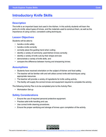
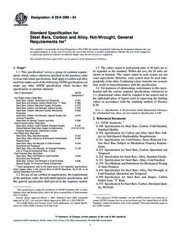
3.The final bedding material provides uniform supportto hold the pipe on line and grade. A relatively loose4”to 6” thick bedding layer is usually adequate.Before installing the pipe, bring bedding material tograde along the entire length of the pipe. Beddingmaterials can be Class I, II or III per ASTM D2321.5.Be sure to apply a generous amount of gasket lubeto the gasket and to swab the inside of the bell. Themost common application method is with a rubberglove although johnny mops can be used for smallerdiameter pipe.6.Dig out a “bell hole” beneath the entire bell andextend approximately 8” beyond the leading edgeof the bell end’s edge with a shovel or boot heel inorder to keep the spigot free of bedding materialand to prevent materials from being pulled in to thebell by the spigot. Materials pulled in to the bell canimpair gasket sealing and cause leaks.FIGURE 2.4.When excavating in Class IV materials (silts, siltyclays and clays), provide a uniform, undisturbedfoundation.5.Class IA materials if used for bedding, must be usedas haunching material to the spring line in a drytrench. To minimize the potential for migration, ClassIA materials should be used to the top of the pipe inwet trenches or in trenches that will fall below thewater table.7.After creating a bell hole and prior to jointconnection, laying a piece of reusable matting orplastic liner in front of the joint will eliminate stoneand/or backfill from being scooped or dragged intothe joint. Remove the matting after joint is home.8.Align the spigot end of the pipe into the bell’sleading edge during joining process. Straightalignment of the joint ends will minimize thepossibility of rolling the gasket.9.Do not push on the bell end of the pipe! Do not usea cable or chain wrapped around the pipe to join thepipe. Use of a nylon strap to pull the pipe isstrongly advised.Assembly of Pipe (Joining)1.Pipe is typically joined by inserting the spigot intothe bell. When jobsite conditions require puttingthe bell on to the spigot, care should be taken notto scoop up backfill material into the joint duringjointing.2.Remove the protective film from the gasket prior toapplying the lubricant or joining the pipe.3.The double sealing gasket is fitted into the spigotvalleys as shown in the drawing below. A whiteline on the front of the gasket will be visible if notproperly seated.4.Make sure the bell and spigot joint is thoroughlyclean and free of soil of any type.BELL & SPIGOTTypical detail of a belland spigot joint forDuroMaxx. A whiteline on the front of thegasket will be visible ifnot properly seated.FIGURE 1.6
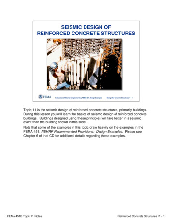
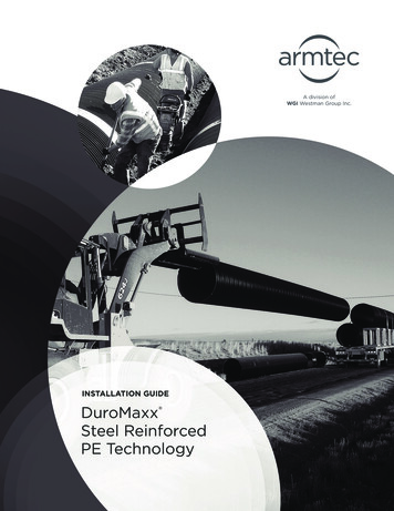
Visit armtec.com for more information.10. The spigot end of the pipe features a “homing mark”that will align with the end of bell when the spigothas been fully inserted into the bell.FIGURE 3.Good joining alonghoming markFor welded Joints, misalignment NOT to exceed 0.25”HaunchingBell EndHome MarkWhite SprayPaint11.Once the pipe has been fully placed in the trenchand prior to backfilling, it is recommended thatthe Engineer or a qualified representative ofthe Engineer approve the trench, bedding andplacement of the pipe.12. After the joint is homed, hand shovel and shovelslice the bedding (i.e. fill and compact) to fill thebell hole for uniform support.13. Cold Weather Note: Rubber gaskets become harderas the ambient temperature decreases. Gaskets tendto compress less, and when combined with bells,jointing becomes less forgiving. Proper bell-spigotalignment, adequate bell and spigot lubrication andrecommended joining procedures all become moreessential as temperatures decreases.1.Proper haunching provides a major portion of thepipe’s load-carrying capability. Poor workmanshipwill lead to excessive pipe deflection and grade andalignment problems. Haunching materials can beClass I, II, or III per ASTM D2321.2.Work enough material under the haunch of thepipe by hand to provide proper compaction andside support. Material shall meet the minimumcompaction requirements of ASTM D2321.3.When trench walls are unstable, sloughing must beprevented so that haunching material can be placedand compacted adequately. The proper use of atrench box or over-excavation can assist in thesecases.4.Don’t let the pipe move when placing material underthe haunch of the pipe.5.Take care not to damage the pipe with shovels, orother construction/tamping equipment.6.Haunch material extends from the bedding/foundation material to the springline elevation.Backfill and Compaction1.14. After proper assembly, take precautions to preventthe pipe from movement prior to haunching andbackfilling.Initial backfill materials extend from the springlineto above the pipe (see page 9 -Standard BackfillDetail) to provide the remainder of the pipe supportand protect the pipe from stones or cobbles in thefinal backfill. Backfill materials that generally followthe requirements of ASTM D2321, such as Class I, II,or III (or approved equal) may be used.2.Native materials meeting the acceptable materialson page 8 can be used as backfill, but should beapproved by the Engineer.Welded Joint Considerations3.Materials must be free from large stones, frozenlumps or other debris.4.Typical trench/backfill details can be found on page9; and acceptable backfill materials and compactionrequirements on page 8 in this document.1.It is critical that the pipe be kept dry.2.For proper welded coupling, misalignment shouldnot exceed 0.25 in.3.It is critical that the gap between pipe ends shouldnot exceed 1.5 in. for proper coupling.4.Please conform to OSHA confined spacerequirements.7
5.Select fill should be placed and compacted to the minimum thickness referenced in the applicable installationdetail before transitioning to native or non-select fill material over the pipe or to pavement.6.Fill above the select fill should be fully compacted.7.As backfill is placed around the pipe, care should be taken to avoid damage to the pipe.8.Backfill height differential from one side of pipe to the other shall not exceed 12”. Only “hand compaction”equipment is allowed over and around the pipe until minimum construction heights are achieved.TABLE 3. ACCEPTABLE BACKFILL MATERIALS AND COMPACTION REQUIREMENTSSOIL OM43AASHTOM145MINIMUMSTANDARDPROCTORDENSITY %Graded or crushed,crushed stone,gravelClass I-556A-1-a85%Well-gradedsand, gravelsand gravel/sandmixtures;poorlygraded sand,gravels and gravel/sand mixtures; littleor no finesClass IIGWGPSWSP576A-1-bA-385%Silty or clayeygravels,gravel/sand/silt or graveland clay mixtures;silty or clayeysands, sand/clay orsand/silt mixturesClass IIIGMGCSMSCGravel and sand( 10% fines)A-2-4A-2-590%
Visit armtec.com for more information.Standard Backfill Detail - Specification & Standard Drawing120”25’-0”36” MINIMUM FOR PIPE DIAMETER 120”18” MINIMUM FOR PIPE DIAMETER 120”9
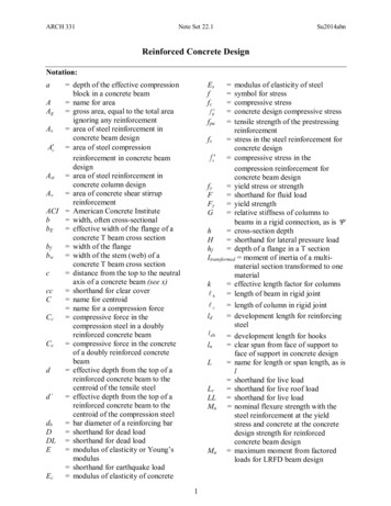
Flowable FillNOTES:These materials are suitable for use with DuroMaxx atthe direction of the Engineer. The contractor must takeprecautions to preclude the dislocation or flotation ofthe pipe during placement of the flowable fill. Shouldthese materials be utilized by the contractor, Contechwill assist with recommendations for restraint to ensureline and grade can be maintained.1.Allowable minimum cover is measured from the topof the pipe to the bottom of a flexible pavement orthe top of the pipe to the top of a rigid pavement.Minimum cover in unpaved areas will be greaterthan for paved areas shown in Table 2 and mustbe maintained. Contact your local Contech SalesEngineer for more information.2.All heights of cover are based on trench conditions.If embankment conditions exist, additional care inthe placement of fill outside the pipe backfill zone isrequired. Your Contech representative can providefurther guidance for a project in embankmentconditions.Embankment Conditions1.DuroMaxx is a superior product that is normallyinstalled in a trench condition. Embankmentinstallations are an acceptable installationapplication.2.In general, the backfill type and placement of thebackfill immediately around the pipe can be thesame as that shown on page 8.3.The width of the select fill zone around the pipeand the type of material placed outside the zone– adjacent to the select fill zone – are critical anddependent upon the pipe diameter and ultimateamount of fill and loads to be placed over the pipe.4.5.In the event of an embankment installation, a backfilldesign should be prepared for the specific siteconditions by the Engineer.Larger diameters may not be allowed or may requireadditional care in backfilling. Only small walk-behindcompaction equipment should be used directlyaround the pipe.Construction LoadsTABLE 5. HEAVY CONSTRUCTION LOADSMinimum Height of Cover Requirements forConstruction Loads.The Minimum Cover should be a COMPACTED Heightof Cover Requirement.Diameter/SpanAxle Load (Kips) 32 5050 7575 100110 15030-422.0 ft2.5 ft3.0 ft3.0 ft48-723.0 ft3.0 ft3.5 ft4.0 ft84-963.0 ft3.5 ft4.0 ft4.5 ft102-1203.5 ft4.0 ft4.5 ft5.0 ft(in)Cover Limits1.Once the backfilling process is completed, thecontractor should take care to maintain the minimumallowable cover height over the pipe and should notifyall other contractors and subcontractors to avoidremoval of fill cover or rutting.For temporary heavy construction vehicle loads, anextra amount of minimum compacted cover may berequired over the top of the pipe.2.The height-of-cover shall meet the minimumrequirements shown in the Table 4. The contractormust provide the additional cover required to avoiddamaging the pipe.3.Minimum cover, shown in Table 4, is measured fromthe top of the pipe to the top of the maintainedroadway surface.4.The contractor should notify all other contractorsand subcontractors to avoid any off-highway orunusual live loads (construction loads) over the pipe.The loads would include but are not limited to:off-highway trucks, earth movers or scrapers, certainpaving and other construction equipment.TABLE 4. HEIGHT OF COVER LIMITS H20-25/HS20-25Pipe Dia. (in)Min. Cover (ft)Max. Cover 25FIGURE 4.Temporary Cover ForConstruction LoadsHeight of Cover10Finished Grade
Visit armtec.com for more information.Joint TestingBe sure to apply lube to the spigot gasket and theinside of the bell of every joint made to ensure a properconnection. Do not pull debris into the bell along withthe lubricated spigot. A bell hole may be needed inorder to achieve this. All pipe must be free of damage ofany kind. DO NOT fill DuroMaxx tank with liquid withoutbeing 100% backfilled.3.Use the leading edge of the blade to cut into theribs of the pipe.4.Bury the blade as much as possible into the pipe asyou proceed.5.The alternative cutting tool for DuroMaxx is ahandheld reciprocating saw. This process will takeabout 2 minutes to cut the steel ribs. There are 9 ribsfor 24” around the pipe circumference.6.For large diameters, square cuts can be achievedTemperature Effects1.DuroMaxx is a superior product and the pipe’sstiffness is not affected by solar absorption orelevated ambient temperatures.2.If large swings in temperature occur from thelocation the pipe is stored and the bottom of thetrench, then the pipe may require conditioning toavoid contraction of the pipe’s length.3.Operating temperatures are not recommendedbeyond 120 F (49 C).from the inside.Manhole or Structure ConnectionsDuroMaxx can be connected to manholes or othertypes of structures using typical methods used by otherflexible pipe products. Please consult the Engineerand your local Contech Sales Engineer to discuss whatmethod is most appropriate for the application.For fixed manhole or structure connections, stack-upof pipe tolerance, line and grade variations and thermaleffects should be considered when ordering totalpipe lengths.Cutting Instructions1.The recommended cutting tool for DuroMaxx pipeis a chop saw and abrasive saw blade. Refer to theOperating Instructions from the saw manufacturerfor additional information.Always use safety glasses when cuttingDuroMaxx pipe and use protective glovesin case sharp edges are exposed.Repairs1.Should damage to the pipe occur at any pointduring installation, the Engineer should be contactedimmediately.2.For larger damaged secti
4. Use a forklift with full-length forks or fork extensions (typically 8 feet), front-end loader or backhoe with fork adapters at full length to engage entire pallet width. Make sure back of forklift is free of protrusions or spikes that could damage the pipe. TABLE 1. DIMENSIONS & HANDLIN