Transcription
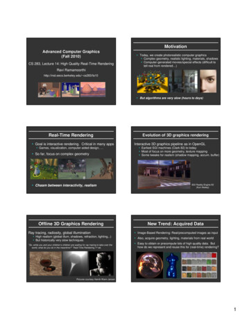
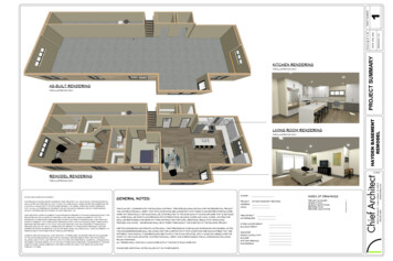
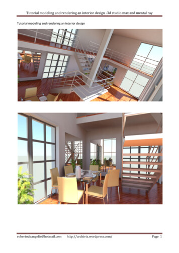
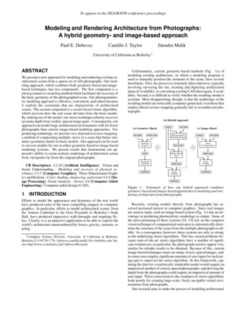
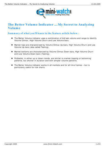
Volume and Surface Renderingof 3D Medical Datasets in Unity 11Soraia Figueiredo Paulo , Miguel Belo , Rafael Kuffner dos Anjos1,21,2Jorge , Daniel Simões Lopes21,2,3, Joaquim Armando1INESC-ID, Lisboa, PortugalInstituto Superior Técnico, Universidade de Lisboa, Lisboa, Portugal3FCSH, Universidade Nova de LisboaREngine consists of a complete Unity (C#) project for interactive volume rendering of 3D Texturesand surface rendering of triangular meshes. Volume data is reconstructed from medical imagedatasets, such as Computed Tomography (CT) or Magnetic Resonance Imaging (MRI), and renderedusing a raymarching shader. Surface renderings are created based on 3D meshes and traditionalshading algorithms such as Blinn-Phong. This tutorial is a step-by-step demonstration of how to usethis project to generate a 3D volume from 2D medical images and render 3D surfaces using Unity 3Dgame engine (https://unity3d.com/).1. Download projectREngine is available for download at the following public repository ine.On the left menu, click on Downloads (Figure 1) and then, Download Repository.Figure 1. REngine Bitbucket Repository2. Import into UnityAfter downloading the .zip file, uncompress the project and open it using Unity. To do so, open theAssets folder and double-click on scene (Figure 2).1
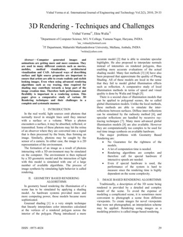
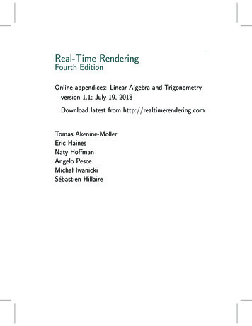
Figure 2. REngine Unity Project – Assets folderBy default, this project will display the volume rendering of a CT dataset (once freely available at theOsiriX DICOM Image Library ge-library/, aliasname PHENIX) that uses the mapping function contained within the TransferFunction.txt file (Figure3). This file consists of a list of Red, Green, Blue and Alpha (RGBA) colors that are assigned eachvoxel according to its original grayscale color intensity. All values are separated by commas. Anexample from one of the file’s lines file would be 1.0000, 0.8673, 0.6368, 0.7500, 180 which meansthat for all voxels with a grayscale color intensity of 180, the new color will be 1.0000 (Red channel),0.8673 (Green channel), 0.6368 (Blue channel), 0.7500 (Alpha channel). All RGBA values are on ascale from 0.0 to 1.0.Figure 3. REngine Unity Project – Initial Display3. Render your own image datasetTo illustrate the steps involved in generating a new volume rendering, we will use a different datasetfrom the OsiriX DICOM Image Library, alias name INCISIX, that is also available inside the REngineproject.2
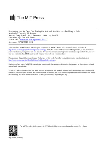
3.1.Create a new folderFirst, create a new folder with the name of your image dataset inside the project’s Resources. Underthe Project window, open the Assets folder and then open Resources (Figure 4).Figure 4. Project window – Resources folderTo create a new folder, click on the Assets menu, Create Folder (Figure 5(a)). Rename the newfolder (Figure 5(b)).Figure 5. (a) How to create a new folder inside Resources; (b) New folder renamed - INCISIX3.2.Import your image datasetDrag and drop your 2D image dataset (.jpg, .bmp or .png format) into your new folder. Select allimages and on the Inspector window activate the Read/Write Enabled option, and change the WrapMode from Repeat to Clamp (Figure 6). Press Apply.3
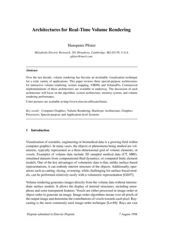
Figure 6. Inspector View – Import Settings for new 2D image dataset3.3.Load your volume renderingIn the Hierarchy window, select the Data Cube gameObject. In the Inspector window, activate theLoader.cs script and fill in the data for your new image dataset (Figure 7). To create your new volumerendering provide the name of the folder from the project’s Resources where your image dataset is(INCISIX), along with the filename of the 3D texture that is going to be generated (INCISIX Texture)and save all changes. Press the play icon (upper bar, right at the middle of the window).Figure 7. Loader script associated with the Data Cube gameObject3.4.Visualize your volume renderingOn play mode, a new .raw file is created and displayed (Figure 8). The user can manipulate thisvolume by activating the Transformer.cs script associated to the Data Cube. Translation and rotationare applied by right or left-clicking, respectively, on the volume while dragging the mouse. Scale iscontrolled through the mouse scroll.4
Figure 8. Game (left) and Scene (right) views - 3D Volume rendering of the INCISIX 2D image dataset4. Render your own modelTo demonstrate the process of creating a new surface rendering we will use a 3D dental implantmodel (available at Sketchup’s 3D Warehouse https://bit.ly/2vfT9bu).4.1.Import the model into UnityOn the Assets menu, click on Import New Asset to select the model you wish to import (Figure 9(a)).This model (Implant screw.skp) will be displayed on the Assets window (Figure 9(b)).ABFigure 9. (a) How to import a new asset into the project; (b) New 3D model imported and displayed onthe Assets window - Implant screw.skp5
To add the model to the scene, drag and drop it from the Assets window into the Scene window(Figure 10).Figure 10. Add the 3D model to the scene - Scene View4.2.Add a light component to the projectTo enhance the visualization of your surface rendering, add a lighting feature to your project. To doso, right-click on the Hierarchy window, Light Directional Light (Figure 11).Figure 11. How to add a Directional Light to the scene - Hierarchy window6
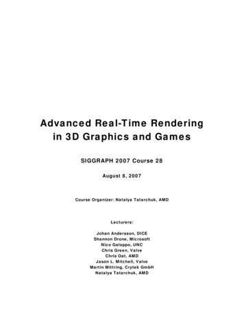
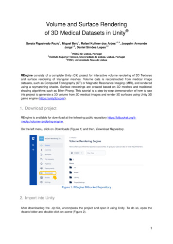
4.3.Visualize your surface and volume renderingsOn play mode, visualize and manipulate the 3D surface and volume renderings (Figure 12).Figure 12. 3D Surface and Volume Renderings: (a) 3D dental implant model; (b) and (c) INCISIX volumeRendering and 3D dental implant surface rendering - Game window7
1 Volume and Surface Rendering of 3D Medical Datasets in Unity Soraia Figueiredo Paulo1, Miguel Belo1, Rafael Kuffner dos Anjos1,2,3, Joaquim Armando Jorge1,2, Daniel Simões Lopes1,2 1 INESC-ID, Lisboa, Portugal 2 Instituto Superior Técnico, Universidade de Lisboa, Lisboa, Portugal 3 FCSH, Universidade Nova de Lisboa REngine consists of a complete Unity (C#) project for interactive volume .