Transcription
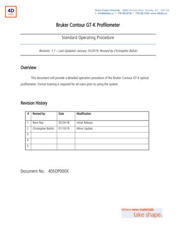
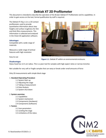
Dektak XT 2D ProfilometerThis document is intended to describe the operation of the Bruker Dektak XT Profilometer and its capabilities. Inorder to gain access on the tool, formal qualification by staff is required.The Dektak XT (Fig 1.1) is a 2D contactprofilometer used to providequantitative information about stepheights and surface roughness for thinand thick films measurements. Thisinformation is collected and analyzedin the Vision 64 application software.AdvantagesCompatible with a wide range ofmaterialsMeasures a wide range of verticalfeatures with high resolutionEasy-to-useFigure 1.1. Dektak XT within an environmental enclosure.DisadvantagesStylus head has 12.5 um radius. This is a poor tool for samples with high aspect ratios or narrow trenchesNot suitable for very soft or fragile samples that can warp or break under small amounts of forceOnly 2D measurements with simple block stage1. Standard Operating Procedure1.1 System Start up1.2 Adjusting the stage1.3 Taking a measurement1.4 Data Analysis1.5 System shut down2. System overview2.1 Capabilities2.2 System mechanism2.3 Components (Hardware)2.4 Components (Software)3. Factors3.1 Scan parameters3.2 Leveling the stage3.3 Limitations of the stylusR. Ravichandran 07/2015 v.1
1.0 Standard Operating Procedure1.1 System start upMake sure system is enabled on BadgerMake sure the system is ONIf not, press white power on button;button should light upTurn on Vision 64 softwareLight within the housing system should turn on to indicate that the system has initialized.Note: do not open the software without the system on first. Otherwise the softwarecrashes. If this happens, press abort on the software error message and start over.R. Ravichandran 07/2015 v.1
Loading samplePlace your sample on the blockSample BlockWARNINGAlways raise the tower prior to loading a sample. Failure to do so candamage the stylus and sample.R. Ravichandran 07/2015 v.1
Lower the stylus towards your sample. If you need to readjust your sample position on the block make sure toraise the tower assembly.To do lower the assembly, click the Tower Down button on the toolbar above the camera’s LiveVideo Display.To raise the tower assembly, click the Tower Up button.If the tower does not move up, click the Tower Home button.TowerDownZoomTowerUpTowerHomeIntensityAfter lowering the tower, adjust the zoom (bottom left) of the camera onto your sample.Adjust the illumination level (bottom right) of the video image displayed on the monitor.R. Ravichandran 07/2015 v.1
1.2 Adjusting the X-Y PositionEnsure the stylus is not touching the sample surface, if it is press the Tower Up button.The Camera display should look like this figure before adjusting the samplePosition the scan start site by using the X-Y positioning levers and micrometers as shown:Sample Block hereX-axis finemicrometerR. Ravichandran 07/2015 v.1X-axis coarseadjustment lever
Y-axis coarseadjustment leverY-axis finemicrometerPress measurement set up and define measurement parametersR. Ravichandran 07/2015 v.1
Scan Type: Select Standard Scan Standard Scan: A normal scan type in which the scan is performed across the surface of asample.The software has other options, but the machine is limited to the standard scanRange: Enter a value that indicates vertical resolution of the scan. When measuring extremely finegeometries, the 6.5 um range provides a vertical bit resolution of 0.1 nm. For general applications, the 1.0nm vertical resolution of the 65.5 um range is usually adequate. When measuring thick films or very roughor curved samples, select the 524 um range with 8.0 nm resolution.Profile: Select from the following: Valleys: Provides 90% of the measurement range below the zero horizontal grid line. Thisoption is used primarily for measuring etch depths. Hills and Valleys: Provides 50% of the measurement range above the zero horizontal grid line and50% below. This option is used in most applications, especially if the surface characteristics of thesample are not well known, or if the sample is out of level. Hills: Provides 90% of the measurement range above the horizontal grid line. This option isused primarily for measuring step heights.Stylus Type: Select the currently installed stylus type: 12.5 umStylus Force: Enter a value between 1 mg and 15 mg. When measuring softer materials (photoresist, pdms,etc) uses the lower values closer to 1mg. When measuring tougher materials use a larger force closer to15mg to get a more accurate reading of the surface features.Length: Enter a scan length between 50 um and 55,000 um (55 mm) for a non-stitched measurement.Duration: Enter amount of time it will take to complete a given scan. Scan duration, in conjunction withscan length, determines the horizontal resolution of a scan. For most applications, a 10 – 20 second scanprovides adequate resolution and throughput.Resolution: Enter the horizontal resolution for the scan length and scan duration. The scan resolution isexpressed in um/sample, indicating the horizontal distance between data points.Sample: Indicates the number of data points that the system should take on the sample during ameasurement.Speed: Indicates the scan speed in units of um/s. A slower scan generally indicates for more accurate results.Tower Up After Scan: Select this check box to make the DektakXT stylus profiler automatically raise thetower to a safe position after each scan.You can save your measurement parameters (.opdx) by clicking saveOr open an existing recipeR. Ravichandran 07/2015 v.1
1.3 Taking a measurementClick on measurementData acquisition window will appear to show the live progress of the scan. Use this time to level the stage asneededSample BlockLeveling knobR. Ravichandran 07/2015 v.1
1.4 AnalysisTo activate leveling, activate Terms Removal (F-Operator) in the Data Analyzer window on the right.Then place the two cursors (R and M) on two points on the graph that you know to be flat on your sample, rightclick, and click Level Two Point Linear.R. Ravichandran 07/2015 v.1
When you proceed to a height measurement, place the cursors (R & M) on the two points you wantto measureInformation about the width and depth of the channel is present in the final data analysis page. The red boxhighlights reference and measurement cursors, as well as the calculated Δ for the step height.1.5 Shutting down the systemAfter taking your measurements, click on the icon "Measurement setup", click Tower Home button, and removeyour sample from the block.Leave the system on and the Vision 64 Software open to the measurement set up menu with the camera displayDisable Dektak XT from BadgerR. Ravichandran 07/2015 v.1
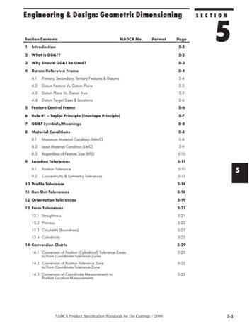
2.0 System Overview2.1 Capabilities Contact profilometer with 12.5um radius diamond tipped stylusManual sample positioning stage with 101.6 x 101.6mm (4 x 4 inches) of X-Y translationManual stage levelingTwo-point cursor software levelingVertical range 1 mm, with 5A resolution (may be limited by stylus geometry)Scan distances of 55 mm (2.16 inches)Force range 0.1 to 3mgCompatible with 6'' to wafer pieces up to 50 mm (1.9 inches) thickColor camera: 1 to 4mm FOVVision 64 software for operation, measurements, and analysis of the Dektak XT2.2 System MechanismThe DektakXT system takes measurements electromechanically by moving a diamond-tipped stylusover the sample surface according to a user-programmed scan length, speed, and stylus force (Fig 1.2). Thestylus is linked to a Linear Variable Differential Transformer (LVDT), which produces and processeselectrical signals that correspond to surface variations of the sample. After being converted to a digitalformat, these surface variations are stored for display and analysis. The factors that affect the resultingmeasurement data will be discussed in more detail in section 2.Input: force from sensorhead as stylus moves acrosssample for a programmedscan length at a specifiedspeedStylusLDVTConverts mechanicalsignal into electricaloutputDigital output for dataanalysisSampleFigure 1.2 Describes an overview of the profilometer measurement mechanism during data acquisition.The Vision64 application calculates and displays the results of user-selected analytical functions formeasuring, step height, surface texture, and other parameters to characterize the profile data. For example, theASH (Average Step Height) analytical function calculates the step height by taking the difference at two markedpoints. The features of the Vision64 software will be described in more detail throughout this manual insubsequent sections.R. Ravichandran 07/2015 v.1
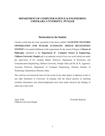
2.3 System Components: HardwareAs shown in Figure 1.3, the DektakXT stylus surface profiler system contains all of the mechanical, electrical,and optical components for sample positioning, sample viewing, and scanning/measurement. The tower assembly ofthe system is detailed in Figure 1.4: USB video color camera, LED illuminator, and a sensor head that magneticallyholds the stylus assembly and contains the feedback mechanisms required to track stylus movements as it rides overthe sample surface. Lastly, Figure 1.5 shows the components of the Emergency Machine Off box (EMO box) whichincludes the power on and power off buttons, along with an emergency off button. After the emergency off buttonshas been depressed, the power cannot be returned to the system until it has been released by turned the knobclock-wise by one-eighth turn.A) Tower AssemblyC) Sample BlockB) ProcessorD) Leveling knobE) X-axis stagemicrometersF) Y-axis stagemicrometersFigure 1.3. Dektak XT hardware components. A) Tower Assembly: contains critical sensor equipment and iscurrently shown in its home position. B) Processor: houses connections between the tool and the computer C)Sample Block: where the sample is placed D) Leveling Knob: To adjust for any tilt during measurements E&F)Stage Micrometers: To adjust the sample positionR. Ravichandran 07/2015 v.1
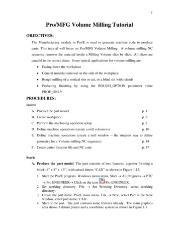
CameraFollows the stylus head'smovements at an angleAdjust zoom with softwareLightShould turn on when systeminitializes.Sensor headApplies scan parameters behindthe stylus.Adjust intensity with softwareStylus12.5 um radius, that transversesacross the sampleAdjust scan parameters withsoftwareFigure 1.4. Overview of the tower assembly components. The Camera and light are angled to the stlyus,and follow its movements. The sensor head and stylus are the heart of the system as they make contactwith the sample on the sample block.Emergency OffTo release: 1/8 turn clockwise untilbutton pops upNote: System will not turn onwhen button is depressedPower on buttonLights up when system is on.If not lighting up, make sureEMO is released.Power off buttonPress to shut off systemFigure 1.5. EMO box for Dektak XT, also includes the power on and power off buttons for the systemR. Ravichandran 07/2015 v.1
2.4 System Components (software)The Dektak XT is controlled and calibrated by using Bruker's Vision 64 software on a Windows 7 OS (Fig1.6). It allows you to adjust the system illumination, position the stylus, program scan parameters, and analyzethe results. The main controls to be concerned on the software are the following menus: measurement setup(Fig 1.7), data acquisition (Fig 1.8), data analysis (Fig 1.9). In section 3, for the standard operating procedure ofthe system, these menus will be discussed in more detail.MeasurementbuttonsPress to takemeasurementCancel tostop easurementOptionsTower control buttonsLive video displayVision 64 software:ZoomIntensityPress this button to open softwareControlscamera focusControls lightFigure 1.6. An overview of the Vision64 components as the Dektak XT initializes. The tower assembly is in thehome position and away from the sample. Highlighted are the key menus of the software.R. Ravichandran 07/2015 v.1
SingleAcquistion orMeasurement:to start scanCancel: to stopcurrent action inprogressOpen/Save: existingmeasurement optionsMeasurementSetup: to get backto this menuMeasurement OptionsTower control buttons: tocontrol tower position andstylus heightLive video displayFigure 1.7. The measurement set up menu critical for setting up the measurement options and various scan parameters.Additionally, use the video display to view your features as you adjust the stage position with the micrometers.
Cancel: to stopcurrent action inprogressLive Data:Direction of Scanvertical displacement v. positionStylusFigure 1.8 The Data Acquisition menu provides live information as the stylus scans across the sample and the measured verticaldisplacement. The sample measured is leveled.
onal filtersfor analysisInformation aboutcursor positionAverage stepheight data (A)Figure 1.9 The Data Analysis menu appears after a scan has completed. At this point, the data can be leveled via software controls and the stepheights can be measured in angstroms under ASH. The horizontal positions of the reference and measuring markers can also be found. Lastly, otherfilters and software controls can be applied to the data set.
3.0MechanismThe Dektak XT is a profilometer that provides quantitative data about the sample's surface (step heights,roughness, etc) by using a contact measurement technique. Measurements are made by a diamond tippedstylus moving laterally in contact with a sample across a specified distance with a specified force. Themeasurements of these vertical features range from 6.5 microns to 1mm with a resolution of 0.5 nm across avariety of substrate surfaces. There are key factors that must be considered in order to obtain reliable,consistent, and accurate results. These are more critical but complementary to the software analysis functions:choosing appropriate scan parameters, leveling the stage, and the limitations of the stylus geometry.3.1 Scan ParametersUnder the Measurement set up tab, there is a Measurement options section on the left-sideScan Type: Select Standard Scan Standard Scan: A normal scan type in which the scan is performed across the surface of asample.Other options are available in the software, but the machine is limited to standard scanRange: Enter a value that indicates vertical resolution of the scan. When measuring extremelyfine geometries, the 6.5 um range provides a vertical bit resolution of 0.1 nm. For generalapplications, the 1.0 nm vertical resolution of the 65.5 um range is usually adequate. Whenmeasuring thick films or very rough or curved samples, select the 524 um range with 8.0 nmresolution.Profile: Select from the following: Valleys: Provides 90% of the measurement range below the zero horizontal grid line. Thisoption is used primarily for measuring etch depths. Hills and Valleys: Provides 50% of the measurement range above the zero horizontal gridline and 50% below. This option is used in most applications, especially if the surfacecharacteristics of the sample are not well known, or if the sample is out of level. Hills: Provides 90% of the measurement range above the horizontal grid line. This option isused primarily for measuring step heights.Stylus Type: Select the currently installed stylus type: 12.5 umR. Ravichandran 07/2015 v.1
Stylus Force: Enter a value between 1 mg and 15 mg. When measuring extremely soft materials(photoresist, pdms, etc) uses the lower values closer to 1mg. When measuring tougher materials use alarger force closer to 15mg to get a more accurate reading of the surface features.Length: Enter a scan length between 50 um and 55,000 um (55 mm)Duration: Enter amount of time it will take to complete a given scan. Scan duration, in conjunctionwith scan length, determines the horizontal resolution of a scan. For most applications, a 10 – 20second scan provides adequate resolution and throughput.Resolution: Enter the horizontal resolution for the scan length and scan duration. The scan resolution isexpressed in um/sample, indicating the horizontal distance between data points.Sample: Indicates the number of data points that the system should take on the sample during ameasurement.Speed: Indicates the scan speed in units of um/s. A slower scan generally indicates for more accurateresults. When measuring taller features, be sure to choose a slower scan speed.Tower Up After Scan: Select this check box to make the DektakXT stylusprofiler automatically raise the tower ti a safe position after each scan.Use Soft Touchdown: If your system includes the 3D Mapping Option, select this check box to make theDektakXT stylus profiler increment the stylus force up to the specified value. This causes the stylus todescend more slowly, thus minimizing the possibility of scratching the sample.3.2 Leveling the StageThe closest possible manual leveling ensures the best profiler performance, and will help gather the mostaccurate data.Level the sample-positioning stage by turning the leveling knob below it(Fig 2.1). As you perform manual stage leveling, follow these guidelines: To view the effect of leveling on the profile trace in real time, perform stage levelingwhile a scan measurement is in progress. To verify that the maximum possible level has been obtained, position the cursors sothat they intersect the same horizontal plane. If the profile trace is extremely off-level, change the measurement range to 5240kÅunder the measurement options. Level the trace, change to the intermediate range, andthen repeat the procedure until the stage is leveled.The best level is achieved by using the 6.5kÅ range.R. Ravichandran 07/2015 v.1
Tower AssemblySample BlockLeveling knobFigure 2.1. Adjust the leveling knob under the sample block to achieve high resolution profilometryR. Ravichandran 07/2015 v.1
3.3 Limitations of the stylusThe stylus shape may have a significant impact on the measurement data as it is the component thatmakes direct contact with the sample's surface. The following section provides information from Brukerabout the geometry of the stylus and its limitations. This stylus tip terminates in a 45 cone with an endradius of 12.5um, as seen in Figure 2.2. When measuring samples with narrow trenches (Fig 2.3), thestylus is unable to correctly verify the widths or reach the bottom of the trench. This is because thewidth of the stylus is caught at the opening. If your sample has many narrow trenches, please measureacross a larger more open area to get a more accurate reading of the film thickness.In order to prevent excess wear or damage to the stylus: Use the camera to verify that no features on the surface exceed the height of the stylus. Lateralcontact between the stylus and the sample is the primary cause of damageWhen measuring taller features ( 10um), use a slower scan speed to limit sudden forces onthe stylusFor more information, please refer to Bruker’s application notes on Stylus Profilometry: DektakStylus Capabilities: How to Choose the Correct Stylus for Any ApplicationFigure 2.1. Shows the dimensions of the diamond-tipped stylus as it terminates at a 45 cone with 12.5um radius at the end. Credit: BrukerFigure 2.2. The geometry of the stylus must be considered as it creates limitations of the accuracy of themeasurements. The 12.5 um stylus can easily measure larger trenches (a) but cannot accuratelymeasure the width (b) and height (c) as the trench aspect ratio increases. Credit: BrukerR. Ravichandran 07/2015 v.1
Dektak XT 2D Profilometer This document is intended to describe the operation of the Bruker Dektak XT Profilometerand its capabilities. In order to gain access on the tool, formal qualification by staff is required. The Dektak XT (Fig 1.1) is a 2D contact profilo